Simultaneous phase matching of optical
parametric oscillation and second-harmonic
generation in aperiodically poled lithium niobate
Tolga Kartalog˘lu, Z. Gu¨rkan Figen, and Orhan Aytu¨r
Department of Electrical and Electronics Engineering, Bilkent University, TR-06533 Bilkent, Ankara, Turkey Received June 5, 2002; revised manuscript received September 10, 2002
We report a simple ad hoc method for designing an aperiodic grating structure to quasi-phase match two ar-bitrary second-order nonlinear processes simultaneously within the same electric-field-poled crystal. This method also allows the relative strength of the two processes to be adjusted freely, thereby enabling maximi-zation of the overall conversion efficiency. We also report an experiment that is based on an aperiodically poled lithium niobate crystal that was designed by use of our method. In this crystal, parametric oscillation and second-harmonic generation are simultaneously phase matched for upconversion of a femtosecond Ti:sap-phire laser to 570 nm. This self-doubling optical parametric oscillator provides an experimental verification of our design method. © 2003 Optical Society of America
OCIS codes: 190.2620, 190.7220, 190.4400, 190.4970, 190.4410, 190.4360.
1. INTRODUCTION
In recent years there has been a growing interest in the simultaneous phase matching of two different nonlinear interactions within the same second-order nonlinear crystal.1–29 Such simultaneous phase matching allows efficient wavelength conversion of lasers to wavelengths that cannot be reached with a single nonlinear process. For example, the combination of optical parametric oscil-lation with second-harmonic generation (SHG) in the same second-order nonlinear crystal facilitates efficient conversion to wavelengths shorter than those of the source laser.3,5 Even though we can reach the same
wavelength range by cascading an optical parametric os-cillator (OPO) and a SHG crystal (either external or inter-nal to the OPO cavity), the conversion efficiency of the two-step process is usually low, and the presence of a sec-ond crystal increases system complexity. Instead, using a single crystal that is simultaneously phase matched for both parametric oscillation and SHG has proved to be more advantageous.3
In second-order nonlinear crystals, the phase-matching condition is most commonly satisfied either by birefrin-gent phase matching (BPM), in which the natural bire-fringence of the crystal is utilized,30 or by quasi-phase
matching (QPM), in which periodic domain reversals fab-ricated into the crystal lead to a grating momentum that cancels the natural phase mismatch.31–33 Both BPM1–4 and QPM8–13 have been used for simultaneous phase
matching of two separate processes within the same non-linear crystal. When the BPM method is used, the two phase-matching conditions are simultaneously satisfied for a set of wavelengths and polarization directions, a par-ticular direction of propagation, and a parpar-ticular tem-perature. This is the result of a coincidental crossing of the phase-matching curves of the two processes.1–4 In the case of QPM, the phase-mismatch term of one process is canceled by the fundamental Fourier component of the
grating momentum; the grating period is chosen to this end. The phase-mismatch term of the second process has to coincide with one of the harmonics of the grating mo-mentum for simultaneous phase matching to occur.8–13 Both BPM and QPM rely on coincidences to work. Given a pair of source and target wavelengths, there is no guar-antee that either method will come up with a suitable crystal design.
When two processes are simultaneously phase matched within the same nonlinear crystal for a given set of wave-lengths, the relative strength of the two processes (the ra-tio of the two effective nonlinear coefficients), is an impor-tant parameter that influences the overall conversion efficiency.5,6 Neither BPM nor QPM allows any room for the adjustment of this important parameter. If one is lucky enough to achieve simultaneous phase matching for a given set of wavelengths, one just has to live with what-ever relative strength these two processes happen to have. This is a restriction that seriously hampers the ca-pabilities of simultaneously phase-matched wavelength conversion systems.
Recently, a number of groups proposed the use of quasi-periodic or aquasi-periodic grating structures to achieve simul-taneous phase matching with QPM.14–29 One approach has been the utilization of quasi-periodic gratings based on Fibonacci sequences14–22; third-harmonic generation (THG)15,17,19,21 and multiple-peak frequency doubling16 (phase-matched SHG for a number of distinct discrete wavelengths) were experimentally demonstrated by use of such gratings. In Fibonacci-based gratings, the loca-tions (in the transform domain) of different Fourier com-ponents of the grating momentum are not independent. Therefore, Fibonacci-based gratings also rely on coinci-dences and cannot be used to cancel any two arbitrary phase-mismatch terms simultaneously. This limitation was alleviated by an extension of Fibonacci-based grat-ings that allows independent placement of the Fourier
components.23–25 Two-peak frequency doubling24 and THG24,25 were experimentally demonstrated by use of these structures. However, neither approach provides a general mechanism to adjust the relative strength of the two simultaneously phase-matched processes. Aperiodic grating structures that are optimized by use of simulated annealing to maximize the conversion efficiency were pro-posed for multiple-peak frequency doubling, tripling, and parametric amplification.26–28 However, this approach does not take pump depletion into account and cannot be expected to yield accurate results. Another method for designing aperiodic grating structures that enables free adjustment of the relative strength of the two processes was proposed29but awaits experimental verification.
Here we describe a simple ad hoc method for designing an aperiodic grating structure to phase match two arbi-trary second-order nonlinear processes simultaneously within the same crystal.34 This method also allows the relative strength of the two processes to be adjusted freely. We also report an experiment that is based on an aperiodically poled lithium niobate (APLN) crystal that was designed by use of our method. In this crystal, para-metric oscillation and SHG are simultaneously phase matched for upconversion of a femtosecond Ti:sapphire la-ser to 570 nm. This self-doubling OPO provides an ex-perimental verification of our design method.
2. SIMULTANEOUS PHASE MATCHING
A second-order关(2)兴 nonlinearity results in the coupledinteraction of three waves whose frequencies are related by3⫽1⫹2.30 The wave vector or phase-mismatch
term ⌬k ⫽ k3⫺ k1⫺ k2 (for collinear waves) plays an
important role in this interaction; the phase-matching condition ⌬k ⫽ 0 has to be satisfied for efficient conver-sion of energy from one wave to another.30 The particu-lar type of nonlinear interaction that takes place depends on the initial conditions at the input facet of the nonlinear crystal; one could have SHG (1⫽ 2→3⫽ 21),
sum-frequency generation (1,2→3⫽ 1⫹2),
difference-frequency generation (1,3→2⫽ 3
⫺ 1), or parametric generation (3→ 2,1).
When two separate processes, say process a and pro-cess b, are simultaneously phase matched, the phase-mismatch terms of both processes,
⌬ka⫽ k3⫺ k1⫺ k2, (1)
⌬kb⫽ k6⫺ k4⫺ k5, (2)
have to vanish for the same direction of propagation and temperature within the crystal (where6⫽4⫹5for
process b). The two processes could have one or two fields in common. Consider the case of THG, for example.10,12,14,15,17–27,29 The input wave is at frequency 1⫽ 2; a SHG process generates3⫽ 21. The
re-sidual fundamental at4⫽1 is then summed with the
second harmonic at5⫽ 3⫽ 21to yield the third
har-monic at6⫽ 4⫹5⫽ 31. Another example is the
self-doubling OPO.3,5,11,13 The input pump wave is at 3; the OPO generates a signal wave at2 and an idler
wave at1, the specific signal and idler frequencies being
determined by the phase-matching condition for the OPO
process. The simultaneously phase-matched SHG pro-cess generates the second harmonic of the signal, where 4⫽5⫽2 and 6⫽ 22. A third example is the
cascaded (tandem) OPO, where the signal of an OPO be-comes the pump of a second OPO.7
In BPM of a single nonlinear process, the interacting waves have different polarization directions, which is nec-essary since a monotonic dispersion curve makes it im-possible to phase match three waves of the same polariza-tion. When two processes are phase matched simultaneously with BPM, a number of different polariza-tion configurapolariza-tions are possible. In general, these polar-ization configurations can be grouped into various classes, each class being governed by a different set of coupled-mode equations.5,6 For common nonlinear crystals, there are only a handful of processes and wavelengths that pro-vide simultaneous phase matching.
In QPM of a single nonlinear process, the interacting waves usually have the same polarization direction. The largest element of the nonlinear coefficient tensor is a di-agonal element for common crystals such as lithium nio-bate, and such a polarization arrangement facilitates the use of the largest nonlinear coefficient (d33 for lithium
niobate). Electric-field poling of the crystal in litho-graphically selected regions creates domain inversions, resulting in a modulation of the sign of the nonlinear co-efficient in the direction of propagation.35 The resulting nonlinear coefficient d(z) ⫽ g(z)dij is a function of dis-tance z in the direction of propagation, where dij is the nonlinear tensor element for the interaction and g(z) is the grating modulation function that can take values only of ⫹1 or ⫺1. A periodic grating function with period ⌳ can be expressed as a Fourier series:
g共z兲 ⫽
兺
p⫽⫺⬁ ⬁
Gpexp共i2pz/⌳兲, (3)
where Gp represents the Fourier coefficients. QPM is achieved by adjustment of period ⌳ so that the natural phase mismatch ⌬ka is canceled by one of the Fourier components of the grating function,32i.e.,
⌬ka⫽ 2
⌳ p (4)
for pth order QPM. In this case the effective nonlinear coefficient that governs the interaction becomes de ⫽ 兩Gp兩兩dij兩. The simplest possible grating function is a rectangular wave with a period of ⌳ and a duty cycle of
Dc. To maximize de, it is common practice to set⌳ to a value that will satisfy Eq. (4) for p ⫽ 1 (first-order QPM) and set Dc⫽ 0.5, in which case 兩G1兩⫽ 2/.
Simulta-neous phase matching of a second process is possible only if the phase-mismatch term of this second process ⌬kb happens to coincide with one of the nonzero harmonics of the grating modulation function. More generally, higher-order simultaneous phase matching with a periodic grat-ing is possible only when both
⌬ka⫽ 2
⌬kb⫽ 2
⌳ q (6)
are satisfied for some particular set of⌳, and integers p and q. (Note that if Dc⫽ 0.5, p and q cannot be even in-tegers, since Gp⫽ 0 for even p in this case.) Even though such circumstances could occur by coincidence,8–13 it is not possible to achieve simultaneous phase matching with periodic gratings for arbitrary phase-mismatch terms⌬ka and ⌬kb. Even if one can find a set of⌳, p, and q to achieve simultaneous phase matching, the interaction will be weak unless either p⫽ 1 or q ⫽ 1. Another handicap of periodic gratings is that the ratio of the effec-tive nonlinear coefficients
deb
dea ⫽
冏
GqGp
冏
(7) cannot be adjusted freely.
An aperiodic grating function can be expressed as
g共z兲 ⫽ lc 2
冕
⫺⬁ ⬁ G共⌬k兲exp共i⌬kz兲d共⌬k兲, (8) where G共⌬k兲 ⫽ 1 lc冕
0 lc g共z兲exp共⫺i⌬kz兲dz (9) is the normalized Fourier transform in the ⌬k domain and lcis the crystal length. Simultaneous phase match-ing is achieved when兩G(⌬k)兩 has peaks located at both ⌬ka and ⌬kb in the transform domain. The effective nonlinear coefficients are given bydea⫽ 兩G共⌬ka兲兩兩dij兩, (10)
deb⫽ 兩G共⌬kb兲兩兩dij兩, (11) and their ratio is
deb
dea
⫽
冏
G共⌬kb兲G共⌬ka兲
冏
. (12)The total energy of the grating function
冕
⫺⬁ ⬁兩G共⌬k兲兩2d共⌬k兲 ⫽ 2/lc (13)
is distributed among all the Fourier components. The fraction of grating energy that is spent toward simulta-neous phase matching is
1 2/lc
冋
冕
⌬ka⫺⑀/2 ⌬ka⫹⑀/2 兩G共⌬k兲兩2d共⌬k兲 ⫹冕
⌬kb⫺⑀/2 ⌬kb⫹⑀/2 兩G共⌬k兲兩2d共⌬k兲册
, (14) where ⑀ is the width of the Fourier peaks in the ⌬k do-main. This quantity should be made as large as possible to maximize the effective nonlinear coefficients. The phase-matching bandwidth ⑀ is equal to the natural phase-matching bandwidth 4/lc regardless of the spe-cific grating function as long as the longest domain length in the crystal is much shorter than lc, a condition that is always satisfied. Therefore, maximizing 兩G(⌬ka)兩2⫹ 兩G(⌬kb)兩2 achieves the same result as maximizing
ex-pression (14). Since the ratio deb/dea is fixed ahead of time, maximization of either Fourier component peak as-sures that the total energy in the wasted components is minimized.
For a given pair of arbitrary phase-mismatch terms ⌬kaand⌬kb, the problem of simultaneous phase match-ing is to find a gratmatch-ing modulation function g(z) so that
• g(z) can assume values only of⫹1 and ⫺1, •兩G(⌬k)兩 has peaks at ⌬k ⫽ ⌬kaand⌬k ⫽ ⌬kb, • the ratio 兩G(⌬kb)/G(⌬ka)兩 is equal to a
predeter-mined constant␣, and
•兩G(⌬ka)兩2[or兩G(⌬kb)兩2] is as large as possible.
3. APERIODIC GRATING DESIGN METHOD
Here we describe a simple ad hoc method for designing an aperiodic grating function g(z) for simultaneous phase matching of two arbitrary second-order nonlinear processes.34 Our method is numerical and iterative; weguess at grating function g(z), calculate its Fourier com-ponents G(⌬ka) and G(⌬kb), determine how well the de-sign requirements are satisfied, and modify our initial guess. Various technical restrictions (such as the mini-mum domain length) are also imposed on g(z) at each it-eration.
For a given pair of⌬kaand⌬kbvalues, we start with a continuous-valued function
f共z兲 ⫽ cos共⌬kaz兲 ⫹ A cos共⌬kbz⫹ 兲, (15) which is composed of the sum of two harmonic functions at ⌬ka and ⌬kb with amplitudes unity and A, respec-tively, and a phase difference. At the first iteration, we set the ratio of the two amplitudes to the targeted effec-tive nonlinear coefficient ratio; i.e., A⫽␣. We also set phase difference to zero. For this f(z) we calculate
g(z) as
g共z兲 ⫽ sgn关 f共z兲兴, (16) where sgn represents the signum function. In other words, we calculate the roots of f(z) and set these to be the locations of the domain walls along the direction of propagation.
The grating mask used in the fabrication of the poled crystal is specified with a certain spatial resolution. This resolution is 0.05 m in the fabrication process that we use. Therefore, at this stage we round off the domain wall locations to the nearest 0.05-m increment. In ad-dition, domain walls that form after electric-field poling are guaranteed to be uniform only if no two domain walls are closer to each other than a critical distance, typically a few micrometers. We tried to be conservative and took this critical distance to be 5 m. In general g(z) can have a number of domains whose lengths are shorter than the critical distance. At this stage we simply discard such domains. In other words, the sign of any domain whose length is less than 5m is flipped, thereby trans-forming this and the two adjacent domains into a single domain. We do this at each iteration by sequentially flip-ping the sign of the shortest domain whose length is less than 5 m until there are no domains left shorter
than this critical length. This elimination method en-sures that the critical length restriction affects the grat-ing minimally.
The resulting g(z) becomes our first guess at a grating function. We then calculate the Fourier transform
G(⌬k). The magnitude of the Fourier transform
natu-rally has peaks located at⌬k ⫽ ⌬ka and ⌬k ⫽ ⌬kb, in addition to various other components located elsewhere. We calculate the magnitudes of these peaks兩G(⌬ka)兩 and 兩G(⌬kb)兩, compare the ratio 兩G(⌬kb)/G(⌬ka)兩 to ␣, and modify the value of A accordingly for the next iteration in small steps. This iterative method converges to a final
g(z) with the desired properties.
This procedure results in an aperiodic grating function
g(z) that has relatively high peaks at ⌬ka and ⌬kb, no domain lengths smaller than the critical fabrication length, and the desired ratio for the effective nonlinear co-efficients. The only question that remains uncertain is whether the resulting effective nonlinear coefficients are as large as possible, i.e., whether兩G(⌬ka)兩 is maximized under the current constraints. We are not aware of any rigorous method that can answer this question. How-ever, we maintain that, as long as the effective nonlinear coefficients are high enough, whether the grating function at hand is optimum is a moot point from a practical point of view. We can get a sense of whether兩G(⌬ka)兩 is high enough by comparing its magnitude with 2/, the largest Fourier coefficient of a periodic grating with Dc⫽ 0.5. Since there are two useful components, it makes more sense to compare兩G(⌬ka)兩2⫹ 兩G(⌬kb)兩2with (2/)2.
We also investigated using the phase difference as another freely adjustable parameter in the iteration pro-cess. We found that even though the value of influ-ences both the individual magnitudes and the ratio of the two Fourier components, its effects are usually within a few percent, as long as the crystal length is much larger than the average domain size. For the sake of simplicity, we set ⫽ 0 at the beginning and do not modify this value.
4. SELF-DOUBLING OPTICAL PARAMETRIC
OSCILLATOR
A self-doubling OPO is based on a nonlinear crystal for which parametric generation and SHG are simulta-neously phase matched. A low-loss resonator that is resonant at the signal wavelength forms the self-doubling OPO cavity. Energy is coupled out of the cavity through the simultaneously phase-matched SHG interaction. A. Coupled-Mode Equations
For collinear monochromatic plane waves
Em共z, t兲 ⫽ Re兵Emexp关i共mt⫺ kmz兲兴其, m⫽ 1, 2, 3, (17) with complex field amplitudes Em, the coupled-mode equations that describe a phase-matched second-order in-teraction are36 dE1 dz ⫽ ⫺i 1de n1c E3E2*, (18) dE2 dz ⫽ ⫺i 2de n2c E3E1*, (19) dE3 dz ⫽ ⫺i 3de n3c E1E2, (20)
where deis the effective nonlinear coefficient and nm rep-resents the refractive indices. A pump field at3 and a
signal field at 2 at the input result in an optical
para-metric amplifier (OPA), where the signal gets amplified and, in the process, an idler field at1is generated.36
In an OPA, the lack of an idler field at the input of the crystal results in field solutions whose intensities are in-dependent of the relative phases of the pump and the sig-nal; the generated idler adjusts its phase to compensate for the phase fluctuations in the input pump and signal beams. Utilizing this property, it is possible to convert the three coupled-mode equations for the complex field amplitudes into three real equations.5 It is also conve-nient to define normalized field amplitudes am such that
am2 represents the photon flux densities at each fre-quencym. In doing this, the phases of Emare chosen such that the required phase relation for the OPA is sat-isfied, and the real and normalized amplitudes amare de-fined as
E1⫽ ⫺i共2ប1/n1c⑀0兲1/2a1, (21)
E2⫽ 共2ប2/n2c⑀0兲1/2a2, (22)
E3⫽ 共2ប3/n3c⑀0兲1/2a3. (23)
The coupled-mode equations for the normalized field am-plitudes can then be written in the form
da1 dz ⫽aa3a2, (24) da2 dz ⫽aa3a1, (25) da3 dz ⫽ ⫺aa1a2, (26) where the coupling constant for the OPA process is de-fined as a⫽ dea
冉
2ប c3⑀0冊
1/2冉
123 n1n2n3冊
1/2 . (27)In the case of SHG, the fundamental field is at4⫽ 5
and the second-harmonic field at 6⫽ 24. Since a4
and a5 are the same fields, the coupled-mode equations
become30 da4 dz ⫽ ⫺ba6a4, (28) da6 dz ⫽ 1 2ba4 2, (29)
with the coupling constant b⫽ deb
冉
2ប c3⑀ 0冊
1/2冉
243 n42n6冊
1/2 . (30)As in the OPA case, the lack of a second-harmonic field at the input has allowed us to write the coupled-mode equa-tions for real field amplitudes, where E4
⫽ (2ប4/n4c⑀0)1/2a4and E6⫽ ⫺i(2ប6/n6c⑀0)1/2a6.
When the two processes are simultaneously phase matched, the signal field is common to the OPA and SHG processes, which become coupled to each other through the signal field. The set of coupled-mode equations that describe this interaction are5
da1 dz ⫽aa3a2, (31) da2 dz ⫽aa3a1⫺ba6a2, (32) da3 dz ⫽ ⫺aa1a2, (33) da6 dz ⫽ 1 2ba2 2. (34)
Using these equations it is possible for us to calculate the net single-pass gain experienced by an input signal field in the presence of simultaneous SHG.5 When the nonlin-ear crystal is placed in an optical cavity that is resonant at the signal wavelength, the single-pass signal gain com-pensates for parasitic linear losses in the cavity at steady state. The resulting intracavity signal field can then be used to calculate the SHG output and the conversion efficiency.5 A theoretical analysis of self-doubling OPA
systems has revealed that the ratio  ⫽ b a ⫽ deb dea
冉
222n1n3 13n2n6冊
1/2 , (35)along with the nonlinear drive
D ⫽ 关aa3共0兲lc兴2, (36)
where lcis the crystal length and a3(0) is the pump field
at the input facet of the crystal, uniquely determines the photon conversion efficiency5
⫽ 2a6
2共lc兲
a32共0兲
. (37)
Therefore, in light of Eq. (12) it is important to be able to adjust the relative magnitudes of the Fourier coefficients of the two processes.
B. Crystal Design
Using our method, we designed gratings for self-doubling OPO that is based on an APLN crystal, with the aim of converting the output of a Ti:sapphire laser at 790 nm to the visible at 570 nm. Given these pump and second-harmonic wavelengths, the signal and idler wavelengths are 1140 and 2573 nm, respectively. We designed two different gratings with prescribed  values of 0.39 and 0.72. These values were chosen based on our estimate of the nonlinear drive we would achieve in our setup. The 20-mm-long lithium niobate crystal was x cut, and all the beams were polarized along the z axis of the crystal to utilize the highest nonlinear coefficient (d33
⫽ ⫺27 pm/V for SHG with 1064 nm as specified in Ref. 37). Lithographic restrictions limited the poled length of the crystal to 18 mm. The aperture size for each grating is 0.47 mm⫻ 0.5 mm, with 0.5 mm being the crystal thickness. The temperature-dependent Sellmeier equa-tions given in Ref. 38 were used to calculate the refractive indices. The crystal temperature was chosen to be 130 °C to avoid photorefractive damage. The phase-mismatch terms for the OPO and SHG processes at the chosen wavelengths were ⌬ka⫽ 3.06663 ⫻ 105 m⫺1and
⌬kb⫽ 7.67070 ⫻ 105 m⫺1, respectively. The target ␣
values for our two gratings were 0.203 and 0.375, and our method converged to A ⫽ 0.385 and A ⫽ 0.847 for the ⫽ 0.39 and ⫽ 0.72 gratings, respectively.
For the two resulting gratings, the fractional error in achieving the prescribed  values was within 2 ⫻ 10⫺5, much smaller than what is necessary to influence the re-sulting conversion efficiency appreciably. When we cal-culated  using Eq. (35), we took the dispersion in the nonlinear coefficients into account by employing Miller’s rule.37
There are 1756 domains in each grating. The smallest domain length is 7.7m (6.1 m), whereas the largest do-main length is 15.2 m (14.8 m) for the first (second) grating. The average domain length for both gratings is 10.3m. Figure 1 shows the length of the inverted and noninverted domains for the two gratings. Figure 2 is an expanded diagram that illustrates domains with domain numbers in the 178–202 range for the first grating ( ⫽ 0.39). The aperiodic nature of the grating function is evident.
Figure 3 shows the magnitude of the normalized Fou-rier transform关兩G(⌬k)兩兴 of the grating modulation func-tions for the two grating structures. For the first grating ( ⫽ 0.39), the fractional errors in placing the first and second Fourier transform peaks at ⌬ka and ⌬kb 关兩(peak location)a,b⫺ ⌬ka,b兩/⌬ka,b兴 are 2.9 ⫻ 10⫺6 and 3.1⫻ 10⫺6, respectively; whereas for the second grating ( ⫽ 0.72), the corresponding fractional errors are 6.1⫻10⫺6 and 2.1⫻ 10⫺6. For both gratings, these er-rors correspond to a shift of the order of 10⫺3 nm in the
Fig. 1. Lengths of (a) inverted and (b) noninverted domains of the first grating (⫽ 0.39) and (c) inverted and (d) noninverted domains of the second grating (⫽ 0.72) as functions of domain number.
prescribed wavelengths of the pump, signal, and second-harmonic beams.
When the newer temperature-dependent Sellmeier equations given in Ref. 39 are used, the phase-matched pump, signal, and second-harmonic wavelengths with these gratings are off by 0.48, 0.34, and 0.17 nm, respec-tively.
The total useful Fourier components 兩G(⌬ka)兩2
⫹ 兩G(⌬kb)兩2 are 0.39 ( ⫽ 0.39) and 0.36 ( ⫽ 0.72). Comparing these values with (2/)2⫽ 0.41, we note that
the gratings designed using our method yield effective nonlinear coefficients that are almost as high as possible. C. Experimental Results
Our APLN crystal was designed with an intracavity-pumped cw self-doubling OPO in mind, hence the rela-tively long crystal length. However, by constructing a simple externally pumped femtosecond self-doubling OPO, we wished to demonstrate the validity of our design method.
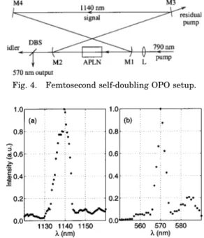
The experimental setup shown in Fig. 4 is based on a singly resonant ring cavity formed by four mirrors that are highly reflective at the signal wavelength. Mirrors M1 and M2 are 100-mm radius-of-curvature concave, and M3 and M4 are flat. The APLN crystal is placed in an oven that is kept at a temperature of 130 °C and posi-tioned at the intracavity focus between M1 and M2. The crystal has antireflection coatings for the pump, signal, and second-harmonic wavelengths on both surfaces. A
mode-locked Ti:sapphire laser with 180-fs-long pulses at a repetition rate of 76 MHz provides the pump beam at 790 nm. The pump beam is focused with a lens (L) of 50-mm focal length and enters the cavity through M1. The fo-cused pump has a 62-m diameter (measured) and the lowest-order transverse mode of the cavity has a 60-m diameter (calculated) at the crystal. We achieved syn-chronization of the signal and pump pulses by moving M3 with a piezoelectrically controlled mount. Mirror M2 was designed to transmit the second-harmonic beam and to reflect the pump beam. The residual (depleted) pump beam is separated from the second-harmonic beam at M2, and leaves the cavity through M3. A dichroic beam split-ter (DBS) separates the second-harmonic beam from the idler beam at the output.
When the pump beam is tuned to a wavelength other than the design wavelength of 790 nm, the signal beam that resonates inside the cavity assumes a value that keeps the OPO process phase matched (if possible). In this case the SHG process is not phase matched, and only a weak parasitic second-harmonic beam is produced. Since there is no output coupler at the signal wavelength, the OPO cavity is severely undercoupled. When the pump beam is tuned to 790 nm, the SHG process becomes simultaneously phase matched with the OPO process, and a strong second-harmonic beam is produced. This reduces the intracavity signal power, since the SHG pro-cess draws power from the signal beam. We measured the wavelengths of the pump, signal, and second-harmonic beams to be consistent with those initially cho-sen. Figure 5 shows the signal and second-harmonic spectra for the second grating ( ⫽ 0.72) when the pump wavelength is 790 nm. The spectra for the first grating ( ⫽ 0.39) are similar.
Figure 6 shows the power conversion efficiency as a function of input pump power for both gratings. The threshold of the self-doubling OPO with the  ⫽ 0.72 grating is 17 mW. This device produces 32 mW of output
Fig. 2. Expanded diagram illustrating a segment of the first grating (⫽ 0.39). Black (white) stripes represent inverted (noninverted) domains. The grid lines are equally spaced.
Fig. 3. Magnitude of the normalized Fourier transform兩G(⌬k)兩 for the (a) first (⫽ 0.39) and (b) second (⫽ 0.72) gratings.
Fig. 4. Femtosecond self-doubling OPO setup.
Fig. 5. (a) Signal and (b) second-harmonic spectra at a pump wavelength of 790 nm for the second grating (⫽ 0.72).
power at the second-harmonic wavelength when the pump power is 234 mW, corresponding to a power conver-sion efficiency of 13.7%. The maximum power converconver-sion efficiency is 17.9% at 103 mW of pump power. This cor-responds to a photon conversion efficiency [see Eq. (37)] of 25.7%. For the self-doubling OPO with the  ⫽ 0.39 grating, the maximum second-harmonic output power is 31 mW at a pump power of 234 mW, corresponding to a 13.2% power conversion efficiency. The maximum power conversion efficiency is 14.7% at 65 mW of pump power, corresponding to a photon conversion efficiency of 21.2%. The general shape of the efficiency curves in Fig. 6 is con-sistent with the plane-wave results of class-A self-doubling OPOs as reported in Ref. 5.
Group velocities of the pump, signal, idler and second-harmonic pulses propagating inside the APLN crystal are all different. This group-velocity mismatch (GVM) re-sults in a spatial separation of these pulses as they propa-gate. This effect has profound consequences on the be-havior of the femtosecond self-doubling OPO. The effective interaction length is limited to distances dictated by GVM. Calculated38 inverse GVM terms for the pump–signal, pump–idler, signal–idler, and second-harmonic–signal pulses are 222, 286, 64, and 699 fs/mm, respectively. The effective interaction length of the pump and signal pulses in the OPO process is approxi-mately 0.8 mm. Even for such a short interaction length, we achieve large pump depletion (⬎50%), indicating a strong pump–signal interaction. However, the relatively high GVM between the signal and the second-harmonic pulses is the limiting factor for the overall conversion ef-ficiency. Another consequence of GVM is a severe broad-ening of the second-harmonic pulses. A signal pulse gen-erates second-harmonic power as it propagates over the whole length of the crystal; the second harmonic gener-ated at earlier portions travel slower than the signal pulse and fall behind as a new second harmonic is gener-ated further down the crystal. We measured the second-harmonic output pulse width to be 2.4 ps. This value is of the same order of magnitude with the total delay be-tween the signal and the second-harmonic pulses over the entire length of the crystal.
Photon conversion efficiencies that reach 26% are a strong indication that the OPO and SHG interactions are simultaneously phase matched in the APLN crystal.
De-tuning the pump wavelength by less than 0.5 nm from the peak reduces the second-harmonic output by more than 90%.
5. CONCLUSION
In conclusion, the method described in this paper facili-tates the design of aperiodic grating structures to quasi-phase match two arbitrary second-order nonlinear pro-cesses (simultaneously) within the same crystal. This method is much simpler than previous approaches to the same problem. Since the relative strength of the two processes can be adjusted freely, the conversion efficiency of the overall process can be optimized. The self-doubling OPO experiment reported in this paper provides experimental verification of our method.
ACKNOWLEDGMENTS
This research was supported in part by the Turkish Sci-entific and Technical Research Council (Tubitak) under grant 197-E050 and in part by the Bilkent University Re-search Fund EE-01-03.
O. Aytu¨ r’s e-mail address is [email protected].
REFERENCES
1. R. A. Andrews, H. Rabin, and C. L. Tang, ‘‘Coupled para-metric downconversion and upconversion with simulta-neous phase matching,’’ Phys. Rev. Lett. 25, 605–608 (1970).
2. V. Petrov and F. Noack, ‘‘Frequency upconversion of tunable femtosecond pulses by parametric amplification and sum-frequency generation in a single nonlinear crystal,’’ Opt. Lett. 20, 2171–2173 (1995).
3. T. Kartalog˘lu, K. G. Ko¨pru¨ lu¨, and O. Aytu¨r, ‘‘Phase-matched self-doubling optical parametric oscillator,’’ Opt. Lett. 22, 280–282 (1997).
4. K. G. Ko¨pru¨ lu¨, T. Kartalog˘lu, Y. Dikmelik, and O. Aytu¨r, ‘‘Single-crystal sum-frequency-generating optical paramet-ric oscillator,’’ J. Opt. Soc. Am. B 16, 1546–1552 (1999). 5. O. Aytu¨ r and Y. Dikmelik, ‘‘Plane-wave theory of
self-doubling optical parametric oscillators,’’ IEEE J. Quantum Electron. 34, 447–458 (1998).
6. Y. Dikmelik, G. Akgu¨ n, and O. Aytu¨r, ‘‘Plane-wave dynamics of optical parametric oscillation with simultaneous sum-frequency generation,’’ IEEE J. Quantum Electron. 35, 897–912 (1999).
7. G. T. Moore, K. Koch, M. E. Dearborn, and M. Vaidy-anathan, ‘‘A simultaneously phase-matched tandem optical parametric oscillator,’’ IEEE J. Quantum Electron. 34, 803– 810 (1998).
8. S. D. Butterworth, P. G. R. Smith, and D. C. Hanna, ‘‘Pico-second Ti:sapphire-pumped optical parametric oscillator based on periodically poled LiNbO3,’’ Opt. Lett. 22, 618– 620 (1997).
9. K. C. Burr, C. L. Tang, M. A. Arbore, and M. M. Fejer, ‘‘High-repetition-rate femtosecond optical parametric oscil-lator based on periodically poled lithium niobate,’’ Appl. Phys. Lett. 70, 3341–3343 (1997).
10. O. Pfister, J. S. Wells, L. Hollberg, L. Zink, D. A. Van Baak, M. D. Levenson, and W. R. Bosenberg, ‘‘Continuous-wave frequency tripling and quadrupling by simultaneous three-wave mixings in periodically poled crystals: application to a two-step 1.19–10.71-m frequency bridge,’’ Opt. Lett. 22, 1211–1213 (1997).
11. C. McGowan, D. T. Reid, Z. E. Penman, M. Ebrahimzadeh, W. Sibbett, and D. H. Jundt, ‘‘Femtosecond optical
paramet-Fig. 6. Power conversion efficiency as a function of the pump power for the first (⫽ 0.39, open circles) and second ( ⫽ 0.72, filled circles) gratings.
ric oscillator based on periodically poled lithium niobate,’’ J. Opt. Soc. Am. B 15, 694–701 (1998).
12. G. Z. Luo, S. N. Zhu, J. L. He, Y. Y. Zhu, H. T. Wang, Z. W. Liu, C. Zhang, and N. B. Ming, ‘‘Simultaneously efficient blue and red light generations in a periodically poled LiTaO3,’’ Appl. Phys. Lett. 78, 3006–3008 (2001).
13. X. P. Zhang, J. Hebling, J. Kuhl, W. W. Ru¨hle, and H. Gies-sen, ‘‘Efficient intracavity generation of visible pulses in a femtosecond near-infrared optical parametric oscillator,’’ Opt. Lett. 26, 2005–2007 (2001).
14. J. Feng, Y. Y. Zhu, and N. B. Ming, ‘‘Harmonic generations in an optical Fibonacci superlattice,’’ Phys. Rev. B 41, 5578– 5582 (1990).
15. S. N. Zhu, Y. Y. Zhu, and N. B. Ming, ‘‘Quasi-phase-matched third-harmonic generation in a quasi-periodic optical super-lattice,’’ Science 278, 843–846 (1997).
16. S. N. Zhu, Y. Y. Zhu, Y. Q. Qin, H. F. Wang, C. Z. Ge, and N. B. Ming, ‘‘Experimental realization of second harmonic gen-eration in a Fibonacci optical superlattice of LiTaO3,’’ Phys. Rev. Lett. 78, 2752–2755 (1997).
17. Y. Y. Zhu, R. F. Xiao, J. S. Fu, G. K. L. Wong, and N. B. Ming, ‘‘Third harmonic generation through coupled second-order nonlinear optical parametric processes in quasiperi-odically domain-inverted Sr0.6Ba0.4Nb2O6 optical superlat-tices,’’ Appl. Phys. Lett. 73, 432–434 (1998).
18. X. Liu, Z. Wang, J. Wu, and N. Ming, ‘‘Characterization of third-harmonic generation in Fibonacci optical superlat-tices,’’ Phys. Rev. A 58, 4956–4960 (1998).
19. Y. Q. Qin, Y. Y. Zhu, S. N. Zhu, G. P. Luo, J. Ma, and N. B. Ming, ‘‘Nonlinear optical characterization of a generalized Fibonacci optical superlattice,’’ Appl. Phys. Lett. 75, 448– 450 (1999).
20. Y. B. Chen, Y. Y. Zhu, Y. Q. Qin, C. Zhang, S. N. Zhu, and N. B. Ming, ‘‘Second-harmonic and third-harmonic generation in a three-component Fibonacci optical superlattice,’’ J. Phys. Condens. Matter 12, 529–537 (2000).
21. Y. B. Chen, C. Zhang, Y. Y. Zhu, S. N. Zhu, H. T. Wang, and N. B. Ming, ‘‘Optical harmonic generation in a quasi-phase-matched three-component Fibonacci superlattice LiTaO3,’’ Appl. Phys. Lett. 78, 577–579 (2001).
22. Y. Y. Zhu and N. B. Ming, ‘‘Dielectric superlattices for non-linear optical effects,’’ Opt. Quantum Electron. 31, 1093– 1128 (1999).
23. K. F. Kashi and A. Arie, ‘‘Multiple-wavelength quasi-phase-matched nonlinear interactions,’’ IEEE J. Quantum Elec-tron. 35, 1649–1656 (1999).
24. K. F. Kashi, A. Arie, P. Urenski, and G. Rosenman, ‘‘Mul-tiple nonlinear optical interactions with arbitrary wave vec-tor differences,’’ Phys. Rev. Lett. 88, 023903 (2002). 25. C. Zhang, H. Wei, Y. Y. Zhu, H. T. Wang, S. N. Zhu, and N.
B. Ming, ‘‘Third-harmonic generation in a general
two-component quasi-periodic optical superlattice,’’ Opt. Lett. 26, 899–901 (2001).
26. B. Y. Gu, B. Z. Dong, Y. Zhang, and G. Z. Yang, ‘‘Enhanced harmonic generation in aperiodic optical superlattices,’’ Appl. Phys. Lett. 75, 2175–2177 (1999).
27. B. Y. Gu, Y. Zhang, and B. Z. Dong, ‘‘Investigations of har-monic generations in aperiodic optical superlattices,’’ J. Appl. Phys. 87, 7629–7637 (2000).
28. Y. Zhang and B. Y. Gu, ‘‘Optimal design of aperiodically poled lithium niobate crystals for multiple wavelengths parametric amplification,’’ Opt. Commun. 192, 417–425 (2001).
29. H. Liu, Y. Y. Zhu, S. N. Zhu, C. Zhang, and N. B. Ming, ‘‘Aperiodic optical superlattices engineered for optical fre-quency conversion,’’ Appl. Phys. Lett. 79, 728–730 (2001). 30. R. W. Boyd, Nonlinear Optics (Academic, San Diego, Calif.,
1992).
31. J. A. Armstrong, N. Bloembergen, J. Ducuing, and P. S. Per-shan, ‘‘Interactions between light waves in a nonlinear di-electric,’’ Phys. Rev. 127, 1918–1939 (1962).
32. M. M. Fejer, G. A. Magel, D. H. Jundt, and R. L. Byer, ‘‘Quasi-phase-matched second harmonic generation: tun-ing and tolerances,’’ IEEE J. Quantum Electron. 28, 2631– 2654 (1992).
33. R. L. Byer, ‘‘Quasi-phasematched nonlinear interactions and devices,’’ J. Nonlinear Opt. Phys. Mater. 6, 549–592 (1997).
34. T. Kartalog˘lu, Z. G. Figen, and O. Aytu¨r, ‘‘A self-doubling op-tical parametric oscillator based on aperiodically-poled lithium niobate,’’ in 2001 IEEE/LEOS Annual Meeting Conference Proceedings (Institute of Electrical and Elec-tronics Engineers, Piscataway, N.J., 2001), pp. 243–244. 35. L. E. Myers, R. C. Eckardt, M. M. Fejer, R. L. Byer, W. R.
Bosenberg, and J. W. Pierce, ‘‘Quasi-phase-matched optical parametric oscillators in bulk periodically poled LiNbO3,’’ J. Opt. Soc. Am. B 12, 2102–2116 (1995).
36. R. A. Baumgartner and R. L. Byer, ‘‘Optical parametric am-plification,’’ IEEE J. Quantum Electron. QE-15, 432–444 (1979).
37. D. A. Roberts, ‘‘Simplified characterization of uniaxial and biaxial nonlinear optical crystals: a plea for standardiza-tion of nomenclature and convenstandardiza-tions,’’ IEEE J. Quantum Electron. 28, 2057–2074 (1992).
38. G. J. Edwards and M. Lawrence, ‘‘A temperature-dependent dispersion equation for congruently grown lithium niobate,’’ Opt. Quantum Electron. 16, 373–375 (1984).
39. D. H. Jundt, ‘‘Temperature-dependent Sellmeier equation for the index of refraction, ne, in congruent lithium nio-bate,’’ Opt. Lett. 22, 1553–1555 (1997).