CO
2LASER GLASS PROCESSING FOR
HIGH POWER FIBER LASER
APPLICATIONS
a thesis submitted to
the graduate school of engineering and science
of bilkent university
in partial fulfillment of the requirements for
the degree of
master of science
in
material science and nanotechnology
By
Bartu S
¸im¸sek
January 2016
CO2 LASER GLASS PROCESSING FOR HIGH POWER FIBER
LASER APPLICATIONS By Bartu S¸im¸sek
January 2016
We certify that we have read this thesis and that in our opinion it is fully adequate, in scope and in quality, as a thesis for the degree of Master of Science.
B¨ulend Orta¸c(Advisor)
Mehmet Bayındır
Hakan Altan
Approved for the Graduate School of Engineering and Science:
Levent Onural
ABSTRACT
CO
2LASER GLASS PROCESSING FOR HIGH POWER
FIBER LASER APPLICATIONS
Bartu S¸im¸sek
M.S. in Material Science and Nanotechnology Advisor: B¨ulend Orta¸c
January 2016
High power lasers have been extensively used in industry, military, astrophysics and medicine for decades. Thanks to developments in optical fiber technology in terms of transmittance, heat resistance, robustness, stability and power en-durance, fiber lasers have recently become more favourable compared to conven-tional laser types such as gas and solid state lasers. Furthermore, high power fiber lasers possess advantageous features like compactness, robustness, all-fiber and alignment-free operation. Besides advances in high power fiber lasers, the struc-ture and power endurance of the critical components as well as their integration quality have been improved. CO2 laser is one the most effective source in glass
processing of optical fibers since it provides stable and homogeneous radiation resulting in a clean process. We have tailored optical fibers to attain low-loss, high quality, mechanically stable integration points by using CO2 laser radiation.
Moreover, we have produced high power fiber laser components such as end-cap and ball lens for manipulating the fiber laser output beam. By tapering the optical fibers, we have fabricated pump and signal combiners which have mode field adapting properties. The 7x1 pump combiner was integrated to the high power fiber laser system developed in our laboratory. Pump source limited power handling capacity of this pump combiner was measured as 850 W with an overall efficiency of 98%. In addition, the same pump combiner was adapted to a high power fiber laser system which was built by using an in-house fabricated active fiber. Finally, we have fabricated a 3x1 laser combiner to combine two in-house fiber lasers with an output power of 1 kW and 690 W at 1080 nm wavelength. The maximum combined power was measured as 893 W by using two ports of this combiner with a launched power of approximately 500 W from each of them. The overall efficiency of the combiner was calculated as 93%. On the whole, we have performed successful glass processing by using CO2 laser radiation. As a
iv
have fabricated critical components for high power fiber lasers such as end-cap, ball lens, pump and laser combiners.
Keywords: CO2 laser glass processing, high quality fiber integration, end-cap,
¨
OZET
Y ¨
UKSEK G ¨
UC
¸ L ¨
U FIBER LASER UYGULAMALARI
IC
¸ IN CO
2LAZER CAM IS
¸LEME
Bartu S¸im¸sek
Malzeme Bilimi ve Nanoteknoloji B¨ol¨um¨u, Y¨uksek Lisans Tez Danı¸smanı: B¨ulend Orta¸c
Ocak 2016
Y¨uksek g¨u¸cl¨u lazerler end¨ustri, sanayi, bilim ve sa˘glık alanında yıllardır sıklıkla kullanılmaktadır. Optik fiberlerin ı¸sık iletimi, ısıya dayanıklılık, sa˘glamlık, kararlılık ve y¨uksek g¨uce dayanıklılık ¨ozelliklerinin teknolojiyle birlikte geli¸simi, son yıllarda fiber lazerlerin gaz ve katı hal gibi geleneksel lazerlerden daha fazla ra˘gbet g¨ormesine sebep olmu¸stur. Bu y¨onelim yekpare yapıdaki y¨uksek g¨u¸cl¨u fiber lazerlerin kompaktlık ve sa˘glamlık gibi ¨ozellikleriyle peki¸smi¸s, hizalama gerektirmeyen yapısıyla daha da avantajlı hale getirmi¸stir. Y¨uksek g¨u¸cl¨u fiber lazerlerdeki ilerlemeler, kritik komponentlerin hem yapısal ve g¨u¸c dayanımları y¨on¨unde, hem de bu komponentlerin entegrasyon kalitesinin arttırılması y¨on¨unde geli¸simlere yol a¸cmı¸stır. Karbondioksit lazerler, sundu˘gu istikrarlı ve homojen ı¸sıma ile optik fiberleri temiz bir ¸sekilde i¸sleyebilen en etkili kaynaklardan biridir. Karbondioksit lazerin avantajları kullanılarak, optik fiber entegrasyon nokta-ları d¨u¸s¨uk kayıp, y¨uksek kalite ve mekanik stabilite olu¸sturabilmek amacıyla i¸slenmi¸stir. Ayrıca, y¨uksek g¨u¸cl¨u fiber lazer komponentlerinden olan ve lazer ¸cıkı¸sını y¨onlendirmeye yarayan fiber u¸c ba¸slı˘gı ve kresel mercek geli¸stirilmi¸stir. Mod alan adapt¨or¨u ¨ozellikleri g¨osteren pompalama ve sinyal kombinarı, optik fiber inceltme tekni˘gi ile ¨uretilmi¸stir. ¨Uretilen 7x1 pompalama kombinarı labo-ratuvarda geli¸stirilen y¨uksek g¨u¸cl¨u lazere entegre edilmi¸stir. Pompalama kom-binarlarının, pompalama kayna˘gı limitli g¨u¸c dayanım de˘gerleri 850 W olarak ¨
ol¸c¨ulm¨u¸s ve ortalama verimlili˘gi % 98 olarak belirlenmi¸stir. Buna ek olarak, ¨
uretilen bu kombinar, enstit¨um¨uz b¨unyesindeki fiber ¨uretim merkezinde ¸cekilen aktif fiber ile entegre edilip, y¨uksek g¨u¸cl¨u fiber lazer sistemi kurulmu¸stur. Son olarak, y¨uksek g¨u¸cl¨u iki fiber lazeri birle¸stirmek amacıyla 3x1 lazer kombi-nar ¨uretimi ger¸cekle¸stirilmi¸stir. U¸c adet giri¸s fiberine sahip olan bu kombi-¨ narın iki giri¸sinden her birisine 500 W g¨u¸c verilmesi ile 893 W lazer g¨uc¨u
vi
kombine edilmi¸s olup, bu kombinarın ortalama verimlili˘gi % 93 olarak hesa-planmı¸stır. Sonu¸c olarak, karbondioksit lazer ile ba¸sarılı bir ¸sekilde cam i¸slenmesi ger¸cekle¸stirilmi¸stir. Optimize edilmi¸s y¨uksek kalitede entegrasyon ve fiber esnetme i¸slemleri sonucu y¨uksek g¨u¸cl¨u, lazerler i¸cin kritik ¨oneme sahip olan bile¸senlerden u¸c ba¸slı˘gı, k¨uresel mercek, pompalama ve lazer kombinarı ¨
uretilmi¸stir.
Anahtar s¨ozc¨ukler : CO2 lazer cam i¸sleme, y¨uksek kaliteli fiber entegrasyonu, u¸c
ba¸slık, yuvarlak mercek, fiber inceltme, pompalama kombinarı lazer kombinarı y¨uksek g¨u¸cl¨u fiber lazer.
Acknowledgement
I acknowledge that apart from my effort, the encouragement and guidance of many other people contributed to the success and existence of this study. First, I would like to express my sincere gratitude to my advisor Assist. Prof. Dr. B¨ulend Orta¸c for giving me this opportunity and his endless help, support, en-couragement, guidance, and supervision for this study. I also would like to thank Prof. Mehmet Bayındır and his group for sharing their knowledge and supplying high quality capillaries and active fibers.
I would like to thank our research group members for their friendship, en-couragement and support. I would like to thank my talented laboratory buddy Yakup Midilli for his encouragement, patience, guidance and friendship, also his support for all works in the laboratory. I would like to thank Dr. Tolga Ba˘gcı for his encouragement, guidance, friendship, and support for my experimental and theoretical work. I would like to thank Canan Kur¸sung¨oz for her sincere friendship, support, patience and positive attitude. I would like to thank again everyone above for helping me to complete my thesis with their endless patience. I would like to thank Levent Ersoy for his sincere friendship, honesty, and support for all technical problems in laboratory. I would like to thank Refik Tuzaklı as my undergraduate and graduate fellow for his sincerity, honesty and friendship. I would like to thank to the new member of our research group O. Benjamin Efunbajo for his friendliness and support. The last and most important, I would like to thank my wife, love, friend, group member and the only one who always supports me, helping me about all problems, encourages me all times, loves me deeply, makes me feel cheerful with her existence, Elif Uzcengiz S¸im¸sek.
I would like to thank Sebahattin U˘gur, Toshiki Kubo and Nasir Usman for helping all technical problems of AFL LAZERMaster LZM-100 splicer with their endless patience. In addition, I would like to thank to UNAM members, friends and staff for their support and friendship.
viii
S¸im¸sek, my little sweet sister Tuana S¸im¸sek, my mother in-law S¸¨ukran Uzcengiz, my sister in-law Yasemin Uzcengiz and my father in-law Orhan Uzcengiz who passed away eight years ago, for their endless love, encourage and support.
I would like to thank TUBITAK. This work is partially supported by TUBITAK under the project number of 113A055. B. O. acknowledges support from the Turkish Academy of Sciences under the TUBA-GEBiP program and Bilim Akademisi - The Science Academy, Turkey under the BAGEP program.
Contents
1 Introduction 1
2 Theoretical Background 4
2.1 Light guiding principles in uniform and non-uniform optical fibers 4 2.1.1 Light guiding in non-uniform optical fibers: Tapering . . . 9 2.2 High power fiber lasers systems . . . 12 2.2.1 Principles and main components of fiber lasers and amplifiers 13 2.2.2 Power limitations of fiber lasers . . . 17 2.3 Integration of optical fibers . . . 19 2.3.1 Fusion splicing of optical fibers . . . 19 2.3.2 Splicing and shaping of optical fibers with CO2 laser . . . 20
2.3.3 Splicing loss . . . 20 2.3.4 CO2 laser radiation - Silica interaction . . . 22
CONTENTS x
3.1 Integration of fiber optics with CO2 laser . . . 26
3.1.1 Splicing of fibers with same cladding diameters . . . 28
3.1.2 Splicing of fibers with different cladding diameters . . . 32
3.1.3 Low loss integration of core offset fibers . . . 34
3.2 End-cap fabrication with CO2 laser . . . 36
3.3 Ball lens fabrication with CO2 laser . . . 38
3.4 Fiber tapering with CO2 laser . . . 41
3.5 Summary . . . 45
4 Pump combiners for high power fiber lasers 46 4.1 Design and numerical study . . . 46
4.2 Fabrication and Characterization of 7x1 Pump Combiners . . . . 48
4.2.1 Fabrication and optimization . . . 49
4.2.2 Characterization . . . 53
4.3 Development of high power fiber laser operating at 1080 nm with 600 W average output power built with in house fabricated 7x1 pump combiner . . . 59
4.4 Development of high power fiber laser operating at 1064 nm with 420 W average output power built with in-house fabricated 7x1 pump combiner and active fiber . . . 64
CONTENTS xi
5 Signal combiners for high power fiber lasers 69 5.1 3x1 kW-class fiber laser combiner fabrication and characterization 69 5.1.1 Fabrication . . . 70 5.1.2 Characterization . . . 72 5.2 Combining in-house built two high power fiber lasers with in-house
fabricated 3x1 laser combiner . . . 76 5.3 Preliminary studies for high quality high power fiber laser combining 80 5.3.1 7x1 fiber laser combiner fabrication . . . 80 5.3.2 Laser combiner with tapered bridge fiber fabrication . . . 81 5.4 Summary . . . 82
List of Figures
2.1 Index types of fibers . . . 5
2.2 Refraction of light . . . 6
2.3 Total internal reflection . . . 6
2.4 Adiabatic taper geometry . . . 10
2.5 Adiabatic taper MM . . . 11
2.6 Double clad active fiber laser . . . 13
2.7 Double-clad fiber amplifier . . . 14
2.8 Combiner types . . . 16
2.9 Optical effects at splice point . . . 21
2.10 Silicon dioxide molecular structure . . . 22
2.11 Co2 transmission spectrum . . . 24
2.12 Si02 Absorption vs. wavenumber . . . 25
LIST OF FIGURES xiii
3.2 Stripper . . . 28
3.3 Surface of cleave . . . 29
3.4 Cleave angle . . . 29
3.5 Same diameter splicing . . . 30
3.6 200-240 um splice . . . 30
3.7 400 um bad splice . . . 31
3.8 400 um successful splice . . . 31
3.9 Different type integration points . . . 32
3.10 Hot and cold splice . . . 33
3.11 Different diameter splicing . . . 33
3.12 Core offset splicing . . . 34
3.13 Core to core splice . . . 35
3.14 Core to core splice 2 . . . 35
3.15 End-cap . . . 36
3.16 End-cap design . . . 37
3.17 End-cap splicing . . . 38
3.18 End-cap splicing 2 . . . 38
3.19 Ball lens design . . . 39
LIST OF FIGURES xiv
3.21 Ball lens fabrication . . . 40
3.22 Ball lens optic microscope . . . 41
3.23 Heat points . . . 42
3.24 400 to 125 tapering . . . 43
3.25 Capillary tapering . . . 44
3.26 Combiner tapering . . . 44
4.1 Combiner Solidworks Simulation . . . 47
4.2 Combiner Zemax Simulation . . . 47
4.3 Combiner housing . . . 48
4.4 Fluorine doped capillary . . . 49
4.5 Capillary tube sketch . . . 50
4.6 Combiner optimization process . . . 50
4.7 Combiner types . . . 51
4.8 Cleaving and splicing combiner . . . 51
4.9 Combiner cleaving optimization . . . 52
4.10 Combiner splicing . . . 52
4.11 Combiner heat sink . . . 53
4.12 SEM image of combiner . . . 54
LIST OF FIGURES xv
4.14 Efficiency of combiner . . . 56
4.15 Heat sinks of diode and combiner . . . 57
4.16 Thermal images . . . 58
4.17 Structure of 1080 nm fiber laser . . . 59
4.18 Simulation of 1080nm fiber laser . . . 60
4.19 1080 nm fiber laser setup . . . 61
4.20 1080nm fiber laser wavelength with and without pump . . . 62
4.21 1080nm fiber laser power and efficiency without pump . . . 62
4.22 1080 nm fiber laser thermal image . . . 63
4.23 1064 nm fiber laser . . . 64
4.24 1064 nm fiber laser setup . . . 65
4.25 1064 nm fiber laser wavelength . . . 66
4.26 1064 nm fiber laser power and efficiency . . . 66
4.27 1064 nm fiber laser thermal image . . . 67
5.1 3x1 combiner capillart tapering . . . 70
5.2 3x1 combiner fiber bundle tapering . . . 71
5.3 3x1 combiner splicing 2 . . . 71
5.4 3x1 combiner splicing . . . 72
LIST OF FIGURES xvi
5.6 3x1 combiner optical characterization setup . . . 73
5.7 3x1 combiner optical characterization . . . 75
5.8 3x1 combiner thermal image . . . 76
5.9 3x1 Laser combiner setup . . . 77
5.10 Fiber laser splice to 3x1 combiner . . . 78
5.11 3x1 Laser combiner results . . . 78
5.12 3x1 Laser combiner wavelength . . . 79
5.13 10-130 Laser combiner . . . 80
List of Tables
4.1 Operation parameters of the laser diodes used in the setup . . . . 56
Chapter 1
Introduction
In 1970, Corning scientists developed a highly pure optical glass which transmit-ted light signals over long distances with low-attenuation. Highly transmissive optical fibers were then demonstrated and they were firstly developed for opti-cal telecommunications so as to substitute low-loss, high-capacity and fast data transfer cable for conventional cables [1,2]. Subsequently, optical fiber technology has been developed and the first low-loss rare-earth element doped double-clad fiber was fabricated in early 1980’s [3]. By the invention of this optical fiber, the first high power fiber laser operations were performed in 1988 [4]. These re-sults sparked a revolution in high power fiber laser industry. The evolution of high power fiber lasers has undergone sudden increment over the past 25 years. During quarter century, the optical fibers have been improved in terms of transmittance, heat resistance, robustness, stability and power endurance as well as developing the critical components for the high power fiber laser. The fiber-coupled laser diode as a pump source, the fiber bragg grating (FBG) as a mirror and the com-biner as a light coupler have also been developed to reach highest laser powers on the fiber laser concept [5]. Today, fiber lasers have numerous advantages over gas or solid state lasers. Firstly, an alignment-free waveguide structure can guide light over long distances with high stability. Secondly, high single-pass gains can be realized not only in amplifier concepts but also in simple resonators with ef-ficient double-clad active medium of an optical fiber. Another advantage of the
fiber laser is that an active fiber can be easily cooled due to its large surface-to-volume ratio. Yet another advantage is the high power-handling capacity of optical fibers arising from the efficient rare-earth dopants in the active medium. Last but not the least, high beam quality can be achieved with single-mode (SM) or large-mode area (LMA) optical fibers [2].
With the developing technology on optical fibers, the diversity of fiber types has increased and their integration for constructing high power fiber laser has gotten complicated. There are basically two methods to integrate fibers, namely mechanical splicing and fusion splicing. Fusion splicing of optical fibers is a welding process of two fibers and has advantages over mechanical splicing in terms of loss, compactness, mechanical strength and stability. There are also several heat sources for fusing optical fibers such as flame torch, filament, electrode arc discharge and CO2 laser radiation [6–8]. Although, all heat sources are used for
fusion splicing of optical fibers effectively, CO2 laser has several advantages for
manipulating optical fibers to fabricate critical components, such as end-cap [9], fiber ball lens [10] and fused pump/signal combiners, by using strong absorption feature of silica (SiO2) at 10.6 µm wavelength. CO2 laser source allows long
tapering processes of optical fibers with clean, stable and homogeneous laser radiation. By tapering the optical fibers, high quality mode field adapter (MFA), axicon and pump/signal combiners can be fabricated. Fused, monolithic, all-fiber pump combiners, which guide light coming from fiber coupled laser diodes into a double-clad active fiber, are critical components for constructing monolithic fiber laser systems. Fused laser combiners are, also, key components for scaling fiber laser power. The output power of fiber lasers can be limited by thermal effects, non-linearity of fiber, facet damage and brightness of the fiber-coupled pump diodes. In order to overcome these limitations, a laser combiner can be used to add the outputs of multiple high power fiber lasers.
In this thesis, by using CO2 laser source, high power fiber laser integration
of same diameter optical fibers, different diameter optical fibers and core offset fibers was studied and optimized for low loss, robust, stable and long-lasting joints. High quality integration of any kind of fiber splicing is an important step to gain the ability of building up stable, robust high power fiber laser systems
with high beam quality. Then, the optical fibers were tailored by CO2 laser
ra-diation to fabricate ball lens and end-cap. Both laser light guiding components were designed and fabricated. The fiber tapering is another CO2 laser glass
pro-cessing which is necessary for optimizing pump and laser combiner production. The fiber tapering was developed and optimized for the optical fibers, the fiber bundles and the capillary tubes. A 7x1 pump combiner was designed, fabricated and optimized in terms of tapering, cleaving and splicing. Afterwards, the struc-tural, optical and thermal characterizations were performed. As an application of this combiner, a high power laser system was constructed by using the in-house fabricated 7x1 pump combiner which was operated at the maximum powers of the fiber coupled laser diodes. Also, optical and thermal characterization of this laser was performed and results were discussed. Another application of 7x1 pump combiner is building a high power fiber laser with both in-house fabricated active fiber and 7x1 pump combiner. The fiber laser was constructed and operated to characterize its optical and thermal performance.
In the rest of this thesis, a 3x1 signal combiner was fabricated and characterized as above. Then, two lasers with an output power of 1 kW and 690 W were constructed and incoherently combined by the fabricated 3x1 laser combiner. Thermal and optical characterization of this setup was carried out. By exploiting CO2 laser glass processing technology, we are able to develop state-of-art key
components for powerful fiber laser systems.
Finally, preliminary studies were conducted in order to obtain all-fiber beam combining with higher quality. For this purpose, 7x1 laser combiner was fabri-cated and characterized structurally. Additionally, a laser combiner with tapered bridge fiber concept was studied and preliminary data were demonstrated.
Chapter 2
Theoretical Background
In this chapter, ray tracing fundamentals, basic properties of step-index fibers and tapering of optical fibers will be introduced. High power fiber laser concepts are discussed and fusion splicing types of the optical fibers are demonstrated. Finally, CO2 laser radiation - silica interaction will be described.
2.1
Light guiding principles in uniform and
non-uniform optical fibers
Light travels through material at a speed which is less than its speed in a vacuum. Therefore index of refraction can be defined as the ratio of the speed of light in vacuum to the speed of light in the material in Equation 2.1.
n = Speed of light in vacuum Speed of light in the material =
c
ν (2.1)
Optical fibers are composed of high refractive index cylindrical core covered by low refractive index cylindrical cladding. According to their profile of the refractive index, optical fibers are classified into two main types which are step-index fibers and graded index fibers. The step-index fiber is the most preferred type of optical fiber. The standard fiber is generally referred as the step-index fiber. The index
profiles of both the step index fiber and the graded index fiber with respect to their radii are shown in Figure 2.1. In a step-index fiber, the refractive index
Figure 2.1: Index profiles of a) step-index fiber and b) graded index fiber accord-ing to their c) core and claddaccord-ing radius.
of the core is uniform up to the boundary of core-cladding and the refractive index decreases abruptly at this boundary. However, in graded index fiber, the refractive index decreases gradually away from the center of core and it drops to the same value of cladding as in the step-index fiber boundary [11].
In order to explain the physics behind light guiding in the optical fibers, the behavior of light should be investigated at the boundary of media. When light travels from a material with one index of refraction to a material with a different index of refraction, the angle of incidence is related to the angle of refraction by Snell’s law which is shown in Equation 2.2 [12].
n1sin θ1 = n2sin θ2 (2.2)
In Figure 2.2, the refraction of light from both lower refractive index to higher one and higher refractive index to lower one is shown. If the light comes from the medium with lower refractive index, the angle of incidence is bigger than the angle of refraction. Also, if the light comes from the medium with higher refractive index, three cases may occur; the first one is light refraction with smaller angle of refraction, the second one is critical angle (θc) principle when
the angle of refraction θ2 = 900 and the last one is total internal reflection(TIR)
which is the explanation of light guiding mechanism inside the optical fibers. The total internal reflection principle is shown in Figure 2.3. If light is guided into the core with the angle of incidence larger than critical angle (θc), it continues to
Figure 2.2: Refractive indices a) n1 < n2 then θ1 > θ2, b) n1 > n2 then θ1 <
θ2 and when θ2 = 900 then θc: Critical angle, d) total internal reflection (TIR);
n1 > n2 and θ > θc.
Figure 2.3: Total internal reflection (TIR) in an optical fiber which has n1(core)>n2(cladding)>n0(air) occurs when θ>θc (Critical angle).
The critical angle is derived in Equation 2.4 from Snell’s law, which is shown in equation 2.2. n1sin θc= n2sin 900 (2.3) θc = arcsin( n2 n1 ) (2.4)
As the light guiding inside the core is limited by critical angle (θc), the fiber
accepts light only for entrance angles within the range 0 < α < αmax. This
maximum angle (αmax) is called acceptance angle which can be calculated also
from the Snell’s law. For optical fiber, the numerical aperture (NA) is commonly used to express this angle. Derived numerical aperture (NA) is shown in Equation 2.6 in terms of the maximum acceptance angle (αmax) and it is also shown in terms
of the index of refractions of fiber in Equation 2.7 [12].
n◦sin αmax = n1sin(90 − θcritical) (2.5)
Using cos θc=sin(90 − θc), cos θc=
q
1 − sin2θcritical and Equation 2.4,
n◦sin αmax = N A (2.6)
Also numerical aperture can be defined with respect to the refractive index of fibers,
N A =qn2
core− n2clad (2.7)
Fiber optical modes are described as a discrete set of electromagnetic fields which can propagate in a cylindrical waveguide. Optical fibers can be classified as single mode fiber (SM) or multi mode fiber(MM) based on the number of modes that propagates through the fiber. The geometry and composition of the fiber designate the V-parameter which determines the number of guided modes in step-index fiber. V-parameter is defined as follows,
V = 2πa λ0
q
(ncore)2− (nclad)2 (2.8)
where a is the radius of core, ncore is the refractive index of core, nclad is the
refractive index of cladding and λ0 is the free space wavelength. Single-mode fiber
is a fiber that only allows a single propagating mode. This mode is supported only in the case of V-parameter< 2.405. For V-parameter> 2.405, the optical fiber begins to support more modes and it turns out to be a multi-mode fiber. In
multi-mode fiber, the V-parameter is related to the total numbers of mode , M, when it is large. The total number of modes M allowed in the fiber is given by
M ∼= 2π 2a2 (λ0)2 Ω = 2π 2a2 (λ0)2 ((ncore)2− (nclad)2) = V2 2 (2.9) where A is the core cross-section πa2 and ω is the acceptance solid angle of fiber which equals to πθ2 = π((n
core)2− (nclad)2) with assumption sinθ ∼= θ for common
numerical apertures. The plane waves can be in two polarization orientations, so Equation 2.9 is multiplied by a factor of 2 [13].
The fundamental mode of an optical fiber, which has a circular symmetry, is bell shaped. Therefore, this fundamental mode could be well described by a single parameter which is mode field diameter [14]. Mode field diameter (MFD) can be approximated by electric field which varies with radial distance r from the fiber axis E(r) = E0e−(
r w)
2
and the optical intensity I(r) = I0e−2(
r w)
2
varies as the square of E [12] [15]. For 1.2 < V < 2.4, the mode waist size (w ) is given by
w ' a(0.65 + 1.619 V1.5 +
2.879
V6 ) (2.10)
where a is radius of the fiber core.
It is clear from Equation 2.10 that the mode field diameter (2w) is related with the V-parameter. When V-parameter decreases below the limit of 1.2, the mode guided inside the core will spread out of the core and expand into the cladding of the fiber.
According to the geometry and the refractive index composition of the single-clad fibers, light is generally guided into the core as it is the case for most of the fibers as shown in Figure 2.1a and b. However, if the fiber has a second cladding with a low refractive index fluorine doped polymer, then this fiber is called double-clad. Light can be guided into the first cladding of fiber and these types of fiber are generally used as the active fiber and low brightness pump light delivery fiber. Double clad fiber will also be mentioned in Section 2.2.1.
2.1.1
Light guiding in non-uniform optical fibers:
Taper-ing
Tapering of optical fiber is a stretching process to make fiber thinner by heat source. The high quality fabrication examples of fiber tapering, capillary tapering and fiber bundle tapering by using CO2 laser technology are given in the Section
3.4. In this section, theory behind single-mode fiber tapering and multi-mode fiber tapering will be briefly introduced. The adiabatic limits for both fiber will also be calculated.
2.1.1.1 Single mode fiber tapering
The taper can be described as an adiabatic taper so that power of fundamental mode propagates along the taper region without coupling to the higher order modes (HOM). Adiabaticity criterion indicates the limits for light propagation inside tapered fibers [16]. In single-mode fiber, fundamental mode propagating inside the core can be conserved until the core of the fiber is tapered down to specific radius. Values that are below this limit lead to coupling from the funda-mental mode (LP01) to next higher order mode (LP02) according to geometry of
the core. Since coupling between the modes is an undesirable case during taper-ing process, the local change in taper radius should vary with little steps, which means that the taper local length should be much larger than the coupling length between LP01 mode and LP02 mode [17]. This can be demonstrated by
δr
r 1 (2.11)
where r is the core radius. The local change of the radius can be formulated in terms of beat length between the fundamental mode and the dominant coupling mode as
δr = LB
dr
dz (2.12)
where drdz is local slope of taper and the beat length can be formulated as, LB =
2π β1− β2
The low loss tapering (adiabatic) criterion can be derived by inserting the Equa-tion 2.13 and 2.12 into EquaEqua-tion 2.11. The adiabatic criterion for single mode fibers can be formulated as
|dr dz| < r LB = r(β1− β2) 2π (2.14)
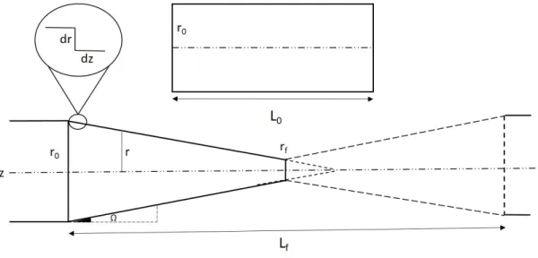
For linear tapers, the taper angle is Ω which is same along the taper, as shown in Figure 2.4. Before tapering the fiber, the core has initial radius r0 and length
Figure 2.4: Adiabatic taper geometry and its parameters for linear tapering of single mode fiber core.
L0. The tapering process reduces waist radius and increases the initial length of
fiber. The final radius of single mode fiber core is rf and the final length is Lf.
Therefore the taper ratio (TR) can be defined as T R = r0
rf and the elongation
ratio (ER) can be defined as ER = L0
Lf and Lf = 2L. The adiabatic criterion for
single-mode fibers can be formulated in terms of the taper length (L), the taper ratio (T R) and the beat length (LB) as in the Equation 2.15,
L
2.1.1.2 Multi-mode fiber tapering
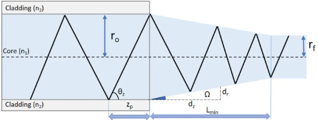
In the multi-mode fiber tapering, the number of propagating modes is much more than that of single-mode fiber. Therefore, instead of using the beat length, LB, a new parameter is defined, namely half-ray period zp which is shown in
Figure2.5 [18]. Adiabatic criterion for the single-mode fibers were shown in
Equa-Figure 2.5: Structure of the tapered multi-mode fiber and its parameters. tion 2.14.The adiabatic criterion for multi-mode fiber can be modified as
dr dz <
r zp
(2.16) where zp is maximum half ray period and is equals to zp = tanθ2rz. Then, adiabatic
criterion can be resulted in terms of ray angle with inserting zp into Equation
2.16, as
dr dz <
tanθz
2 (2.17)
The local slope of taper can be expressed in terms of the solid angle (Ω) in the Equation 2.18 and it is demonstrated as
tanΩ < tanθz
2 (2.18)
In Figure 2.5, the minimum taper length is shown and it can be calculated in terms of untapered (r0) and tapered(rf) radius of fiber and the ray angle (θz). It
is demonstrated as r0− rf Lmin < 2r0 2zp (2.19)
Finally, it can be deduced in terms of the untapered and tapered diameter of fiber and ray angle (θz) as
Lmin ≥
Duntapered− Dtapered
tanθz
(2.20) Therefore, minimum taper length for multi-mode fibers depends on the numerical aperture (NA) of propagated light and the diameter of the tapered and untapered fiber.
In this section, light guiding principles in uniform and non-uniform optical fibers were introduced. In the following section, high power fiber laser systems will be described in terms of their components and power limitations.
2.2
High power fiber lasers systems
In 1960’s, the first rare-earth doped fiber lasers were demonstrated which pro-duced a few milliwatts at a wavelength of 1 µm [19, 20]. Since the beginning of the decade, there have been rapid developments which led to high-power fiber lasers with output powers of hundreds of watts or few kilowatts. The average output power of continuous-wave fiber lasers, having diffraction-limited beam quality has been increasing since in the early 1990s [2]. In 1999, 110 W fiber laser using Yb doped fiber which had a rectangular inner cladding was demon-strated [21]. In early 2004, 306 W all-fiber linearly polarized ytterbium (Yb) doped fiber laser was demonstrated [22]. Shortly after, Yb doped 610 W fiber laser, which has D-shaped active fiber, was shown [23]. In late 2004, kilowatt lev-els were reached by using the cladding pumped approach on fiber lasers and using a simple end-pumped ytterbium doped fiber laser [24]. Additionally, large-core design and fabrications refinements have led to reached single-mode operation. In 2009, multi-kW level fiber laser was demonstrated with near diffraction limited light [25]. Besides improvements in the output power, well known monolithic structure, compactness, low running cost, high efficiency and beam quality of fiber lasers are of great interest in various applications [26].
In this chapter, basic principles of a fiber laser will be introduced. The main components of high power fiber lasers such as double-clad active fibers, fused combiners and laser diodes will be described briefly. The power limitations of fiber lasers and high power beam combining as a solution for these limitations will be investigated.
2.2.1
Principles and main components of fiber lasers and
amplifiers
In order to build highly efficient, long-term stable, compact and robust high power fiber laser system, it is crucial that the fiber laser system should have monolithic architecture [27]. There are two concepts to reach high power levels with high quality light and all-fiber architecture. The first concept is the double-clad fiber laser which is shown in Figure 2.6.
Figure 2.6: Illustration of double-clad fiber laser.
In this structure, the low brightness multi-mode light is guided from the be-ginning and it is taken out from the output as high brightness near single-mode light. The brightness is converted from low to high inside the fiber structure. In order for a fiber laser oscillator to operate, there are several main components
such as fiber coupled laser diode, pump combiner, fiber bragg gratings (FBG) and active fiber [5]. In principle, the pump light that comes from the fiber-coupled laser diodes is directed through the active medium with or without the pump combiner. When the coupled light passes through the rare-earth atom doped core, the pump photons are absorbed by these active ions and bring them to the excited state. Then, the emission occurs through stimulated emission and emitted signal photons are guided into the core of fiber. The fiber laser resonator is built up by confinement of emitted signal photons within the core of the fiber using fiber bragg grating (FBG) as a mirror. These mirrors cause the fiber lase dominantly at a specific wavelength [28].
Figure 2.7: Illustration of double-clad fiber amplifier
The second concept is the fiber amplifier which is commonly called as master oscillator power amplifier (MOPA). The MOPA architecture is shown in Figure 2.7. This structure contains mainly fiber oscillator that generates low power seed signal and the amplifier part which is composed of the pump diodes and double-clad active fiber. The pump light is also absorbed by rare-earth atoms and emission occurs again through stimulated emission as in the case of fiber laser resonator. However, the emitted signal photons is not confined by FBG, the seed signal are amplified by domination of seed source wavelength. The production of high brightness fiber laser is introduced briefly on these two concepts. Also, all the main components of fiber lasers and amplifiers are basically introduced below
based on the order of light passing through them.
The fiber-coupled laser diode is the main and the first element of the fiber laser. The fiber-coupled laser diodes are produced with several configurations, which are single-emitter, vertical stack, horizontal stack or bar modules so that the light can be coupled into the fiber with high efficiency and high power out-put levels can be achieved. There are fiber-coupled laser diodes with different characteristics in terms of output power, wavelength range and diameter of the coupling fiber. The maximum delivered output power commercially available in the market is 1 kW fiber-coupled laser. Moreover the wavelength range of this diodes varies between 790 nm and 1940 nm [29–33]. Also, the laser diodes can be used in high power laser systems with the output fibers having diameter from 100 µm to 600 µm. For instance, high brightness, 160 W light coming from the laser diode can be coupled into the 100 µm core fibers [31]. The ability of highly efficient light coupling to fibers with different diameters enables the use of a variety of combiners and active fibers in the fabrication of novel high power lasers [34].
Combiner is a device that provides very high coupling efficiency over a wide wavelength range from multiple sources into one output fiber. It is a critical component for pumping high power fiber lasers and amplifiers and for combining laser outputs incoherently. All-fiber combiners are necessary to build monolithic, alignment free and robust fiber laser systems. There are mainly two types of combiners; the first one is pump combiner and the second one is laser signal combiner. Pump combiner is generally fabricated with MM single-clad fibers, while laser combiner is fabricated with SM fibers. The principle of pump combiner is delivering the pump light from the fiber coupled laser diodes through the fiber bragg grating or double-clad active fiber with low loss. On the other hand, the principle of laser combiner is combining high power lasers without compromising the quality of light. The fabrication of combiner includes seven approaches to integrate double-clad fiber which are side coupling, distributed side coupling, side coupling with bridging fiber, tapered fiber bundle, fiber bundle integrated bridging fiber, side coupled signal fiber and side coupled signal fiber with capillary tube collapsing.
Figure 2.8: Combiner fabrication approaches; a) side coupling, b) side coupling with bridge fiber, c) fusion of MM fibers to signal fiber, d) fusion capillary tube to signal fiber, e) distributed side coupling, f) tapered fiber bundle and g) tapered fiber bundle with bridge fiber
In Figure 2.8a, a side coupling of a multi-mode pump diode fiber to double-clad active fiber is depicted. It is important that the fiber should be integrated with an angle in order to couple pump light into pump core of the fiber [35–37]. In Figure 2.8b, side coupling of multi-mode pump diode fibers using bridging fiber is illustrated. In this concept, up to twelve fibers can be integrated through bridge fiber without changing uniformity of an active fiber [38]. In Figure 2.8c, coupling of multi-mode pump fibers to a single-mode signal fiber is shown. In this concept, side-pumped signal fiber is spliced to the active fiber. In Figure 2.8d, the same integration approach is applied between the signal fiber and the active fiber as illustrated in Figure 2.8c, but in this approach, a capillary tube are collapsed on signal fiber. In Figure 2.8e, distributed side coupling approach is
shown [39–41]. The pump fiber is coiled and fused along double-clad active fiber. Besides these side pumping approaches, there are also end-pumping approaches, which are shown in Figure 2.8f and g. In Figure 2.8e, tapered fiber bundle is obtained by tapering the fiber bundle down to the diameter of double-clad active fiber and splicing with it. This is the most common concept among commercial combiners [42–48]. The tapered fiber bundle combiner may include a single-mode signal feed-through the fiber to build amplifier systems or seeding mechanisms. In this thesis, this type of combiner is fabricated and characterized in Section 4.2. Finally in Figure 2.8g fiber bundle integrated to bridging fiber is depicted. This approach is generally used on laser combiner concepts to combine high power lasers which is presented as preliminary data of this thesis. After pump light is guided through the double clad active fiber by combiner, the principles that were mentioned above take place and the signal light trapping in the core of the double-clad active fiber by fiber bragg gratings are introduced below.
Double-clad active fibers are composed of a rare-earth element doped core, an undoped hexagonal, rectangular or d-shaped first cladding as a pump core and a UV-curable, high temperature resistant polymer coated second cladding with low refractive index. In this thesis, we use Y b-doped double-clad (Nufern LMA-YDF-20/400-M) and in-house fabricated active fibers to build up fiber laser that is shown in Section 4.3.
Fiber Bragg gratings (FBG) are made by exposing periodic pattern of UV radiation or femtosecond pulses to the core of single-mode fiber. The working principle of FBG is based on the periodicity of the refractive index of the exposed pattern, which satisfies the Bragg condition where λbragg = 2nΛ. In that way, the
light with a specific wavelength for each index and periodicity can constructively interfere from the grating structure [49].
2.2.2
Power limitations of fiber lasers
Power limitations of fiber lasers are imposed by thermal effects, non-linearity of fiber, facet damage and brightness of the fiber coupled pump diodes [50]. There
are several limitations which are caused by thermal effects. The first one is heat conversion of unabsorbed pump light at gain medium. The other thermal effect is melting core by heat power deposition per unit length. The last thermal effect that limits the power is thermal lensing which is created by heat induced tem-perature gradient in the core of fiber. There are also non-linear effects such as stimulated Raman scattering (SRS), which is a nonlinear response of the optical medium due to vibrational or rotational degrees of freedom, and stimulated Bril-louin scattering (SBS), which is caused by generated acoustic phonons related non-linearity of a medium. The facet damage is melting and fracturing of end face of the fiber when the power density is over the breakdown threshold of the glass matrix. Pump diodes have limited brightness for coupling into the optical fiber, number of diodes are limited also due to the limit of maximum input port of pump combiners. All these effects limit the maximum power and quality of high power lasers. These limitations can be overcome by modifying the fiber laser oscillators with cooling equipment or light guiding components such as combiners and end-caps. In order to reach high power levels, there is also another solution which is high power beam combining.
2.2.2.1 High power beam combining
High power beam combining is coherent or incoherent laser beam combining of fiber lasers with free-space or all-fiber components. For coherent beam combining, it is necessary to control the phase of single frequency lasers to let them interfere constructively. Incoherent beam combining can result in several kW level near diffraction limited light combination without controlling phase of lasers. Inco-herent beam combining is not only performed with free-space components but also with all-fiber laser combiners which can reach up to 5kW power levels with high quality lights [51, 52]. In this thesis, high power beam combining with in-house fabricated combiner and preliminary data for high quality high power laser combiner with tapered bridge fiber is given in Section 5.
2.3
Integration of optical fibers
The integration of fiber laser components and fibers have significant importance to build up robust, monolithic, low loss, high power lasers. In this section, fusion splicing is basically introduced and advantages of CO2 laser source are discussed
in terms of splicing and shaping optical fibers compared to the other heat sources.
2.3.1
Fusion splicing of optical fibers
The fusion splicing of optical fibers is a welding process of two fibers with high-strength, low-loss, long lasting and stable integration point. Unlike the mechan-ical splicing of two fibers, the fusion splicing are dust-free, alignment-free and temperature independent [53]. Also, fusion splice has many advantages over other interconnection methods of optical fibers such as free space coupling and mechan-ical splicing. Fusion splicing joints have very tight cross-section areas almost like the original fiber when it is coated with polymer. During the fusion splicing, fiber ends are softened and also viscosity of silica is decreased with increasing temper-ature [54], then they are merged to each other by melting as the low-loss high strength joint. The fiber softening point is approximately 1800 oC as shown in
Figure 3.23. In order to reach this temperature limit, there are few heat sources such as flame torch, electrode arc discharge, filament heater and CO2 laser. All
splicing methods have advantages and disadvantages with respect to each other. Flame torch is the oldest method for fusion splicing and tapering process. It has been used from early 1960’s to the present. Even if strong splices are obtained [6], it is not useful for fusion splicing anymore because of not having homogeneous and stable heating. The electrode arc discharge [7, 55] and filament heater are common heat sources which are used in recent fusion splicers. A typical tungsten filament is used as a heat source in the filament heater. This method supplies homogeneous heat on the fiber and allows splicing to larger fibers, fabricating cou-plers and other high-heat applications. However, filaments need to be changed based on the application and they don’t work above 50 minutes operation. Also, ablated filament may be deposited on silica glass during splicing or tapering. The
electrode arc discharge technique is widely used as a practical source which can heat homogeneously for different size of fibers by creating plasma field of super heated air. This method is reliable and easy to use for many types of fibers. In our laboratory, we are working with electrode arc discharge splicer to build our high power laser systems which are shown in Section 5.2. However, this technique also has a disadvantage that the vaporized silica deposits on electrode tips which leads to contamination on the optical fiber during the splicing process. CO2
laser splicers are used most recently for advanced splicing as well as tapering, fabrication of end-cap and ball lens and collapsing tubes.
2.3.2
Splicing and shaping of optical fibers with CO
2laser
CO2 laser is a very clean heat source for the silica based optical fibers. During
the heating process, there is not any contamination and deposition on the fiber surface. Unlike flame, arc discharge and filament source heating mechanisms, which are based on heat radiation and conduction, the heating mechanism of CO2 laser source exploits strong absorption of light having 10.6 µm wavelength
on the silica. This absorption is caused by elastic vibration of oxygen (O) atom between two silicon (Si) atoms. Interaction between CO2 laser radiation and
silica will be explained in detail in Section 2.3.4. Silica based optical fibers can be integrated and processed by using CO2 laser thanks its stable and repeatable
laser power [56]. In this thesis, all glass processes are performed by CO2 laser
splicing system which is introduced in Section 3.1.
2.3.3
Splicing loss
The optical fiber splicing quality may differ according to position, composition, diameter, geometry, alignment and cleaning of the fiber and its end-face. At the end of splicing process, the guided light signal may undergo four fundamental optical effects such as transmitted signal into same mode, reflected signal, trans-mitted signal into another mode and radiated signal depending on the quality
of the integration point. Such optical effects are shown in Figure 2.9 [53]. The
Figure 2.9: Optical effects that may occur at splice points: Radiated signal, transmitted signal into another mode, transmitted signal into same mode and reflected signal.
first effect is the transmission signal into identical mode in which incoming light is guided from the launching fiber to the receiving fiber by preserving its optical mode. This effect is expected when two optical fibers are perfectly welded. Re-flected signal from the splice point is observed if the splicing results in bubble, core axial offset, core step or line. According to the reflected signal intensity, in-terference, parasitic lasing or pulsing may be observed in the optical fiber. Also, the mode field diameter mismatch, curved core, angled core and the splice results that are mentioned above may convert the signal into another mode as an optical loss. If the splicing is performed with serious symptoms, the launched light may be directed towards the outside of fiber. This causes heating of the integration point of the two fibers. The splice loss can be calculated by total launched power and total received power as shown in equation 2.21.
ΓSplice(in dB) = 10log
PLaunched
PReceived
(2.21) Losses from 0.1 dB to 0.05 dB can be discussed as a good splice. In this thesis, splice loss of all the fibers, which we have worked with, yielded values in the range mentioned above.
2.3.4
CO
2laser radiation - Silica interaction
Silica (SiO2) is the main ingredient of most glasses and has a tetrahedral structure
which means four oxygen (O) atoms surround a silicon (Si) atom at the center as shown in Figure 2.10. Structure of silicon dioxide allows forming glass on its own
Figure 2.10: Illustration of Silicon Dioxide (SiO2) lattice structure and (CO2)
Laser radiation on (Si − O) bond.
and also supports the base for many oxide glasses such as sodium oxide (N aO2),
calcium oxide (CaO), magnesium oxide (MgO), aluminum oxide (Al2O3), boron
trioxide (B2O3), or lead oxide (PbO) [57]. Pure silica glass has a very high
melt-ing point, high chemical durability and low thermal expansion coefficient. These properties of silica glass can be modified by composing oxide glasses with silica. Composition of them can provide better chemical durability, lower melting point, higher refractive index and viscosity of glass. Therefore, silica-based fibers have many advantages over fibers which are formed with other types of glass. These fibers demonstrate almost all properties of silica and additionally support very high damage thresholds, low optical nonlinearity, mechanically robustness, high bending tolerance [58]. Hence, silica based fibers are commonly used for fiber laser applications, especially in high power fiber laser systems.
In this study, fibers that are used for CO2 glass processing applications are
generally made of fused silica. Fused silica (fused quartz) is silica glass hav-ing amorphous (non-crystalline) structure and it is produced by fushav-ing (melthav-ing) high-purity silica sand. In general, there are three types of manufacturing fused silica. The first one is the electric fusion, which is the most commonly used one. The second one is flame fusion, which is a process consisting of trickling silica sand into high temperature flame. The third one is the flame hydrolysis which is a process (synthetic production) consisting of highest purity fused silica nano-droplets formed by hydrolysis of silicon tetrachloride (SiCl4) inside a hydrogen
oxygen torch [59]. For all types of product, silica has a wide range of high optical transparency from ultraviolet (UV) wavelength 0.2 µm to infrared (IR) spectral region wavelength 3.5 µm. This transparency range limitations can be changed from 0.2 µm to 0.4 µm and 3.5 µm to 2.5 µm by modifying silica glass. Light ab-sorption of glass in the range below 0.3 µm is dominated by electronic excitation of molecules, while molecular vibrations are dominated in the IR range [60]. For successful laser glass processing, choice of laser source is restricted with the ab-sence of available laser sources which are working on exceeded limit wavelengths. In the UV regime, F2 laser is operating at 157 nm and excimer laser is operating
at 193 and 247 nm and these lasers strongly couple energy into glass via defects or near-band edge states, providing one approach for micro-machining glass or driving refractive index change on nanosecond or longer time scales [61]. In IR regime, there is only CO2 laser source working at 10.6 µm wavelength band.
Figure 2.11 shows transmittance of fused silica glass in the range of 2.5 µm to 12 µm and the band between 9.4 µm and 10.6 µm is shaded because it refers to operating spectrum of common CO2 laser sources [63]. As it is clear from this
figure, fused silica absorption range (8 µm and 10.6 µm) is matched with CO2
laser source emission wavelength indicated in the figure above. The tetrahedral structure that is shown in Figure 2.10 forms around negatively charged silicon atom and it has a certain geometrical shape likewise gravity center of positively charged atoms. Energy of the IR electromagnetic field will be absorbed as a re-sult of generated dipole by molecular vibration of the structure defined above.
Figure 2.11: Transmission spectra of a pure fused silica (Suprasil) sample in range of 2.5 µm to 12 µm [62].
The movement of the oxygen atom which is bonded to adjacent silicon atom with Si − O bond results in coupling of the two Si − O vibrations. Bond strength and vibration frequency both depend on the Si and O atoms in the bond and on the other neighbors of the silicon atom [64]. The band of high absorption in the range of specific wavelengths is attributed to the bond-stretching vibration between the Si and O atoms in a Si − O − Si bridge structure.
According to the composition of silica, the absorption peak position and its shape of stretching vibration modes can vary as shown in Figure 2.12. In this Figure, absorption coefficient peaks of SiOx shifts from 940 cm−1 to 1150 cm−1
while oxygen content increases. It is also proved that CO2 laser is a very efficient
source for processing silica based glass. Laser processing of silica glass has contin-uing attention as part of the improvement of new technologies for micro-optical fabrication applications and for building up stable, robust, high power fiber lasers and their components.
Figure 2.12: Position and shape of the absorption peak assigned to the stretching vibration mode of the Si−O−Si bridge are dependent on the oxygen content [64].
Chapter 3
CO
2
laser glass processing of
optical fibers
In this chapter, applications of CO2laser processing of optical fibers that are made
up of fused silica will be mentioned. Applications begin with low loss integrations of optical fibers which have same cladding diameters, different cladding diameters and core offset. Then, fiber tapering will be described and examples of fabrication will be shown. The chapter also describes two applications of CO2 laser glass
processing on optical fibers. The first one is end-cap fabrication and the second one is ball lens fabrication on optical fibers.
3.1
Integration of fiber optics with CO
2laser
In chapter 2.3.1, integration types of optical fibers are introduced and potential splice loss symptoms are exhibited. Solutions and examples for low loss integra-tions will be mentioned briefly in this section. We will first start introducing integration of optical fibers with same cladding diameters, different cladding di-ameters and also we will show the integrations of core offset fibers by CO2 laser.
For all applications in this thesis, the AFL LZM-100 LAZERMaster Laser Splic-ing System is used as a CO2 laser source. The main structure of the laser system
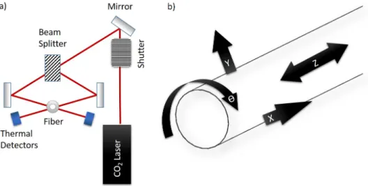
is shown in Figure 3.1. As presented in this figure, CO2 laser radiation having
Figure 3.1: (a) Depiction of the CO2 Laser source, (b) Available coordinates of
movement of the fiber in this system.
4 mm beam spot, surrounds the fiber to heat it homogeneously. Power (max. 30W ) and wavelength (10.6µm) stability of this laser provides low loss integra-tions and high quality components. In order to prevent integration losses, there are few steps to be carried out including stripping and cleaving fiber.
Optical fibers are generally polymer coated right after drawing in order to protect them from subsequent handling damage. Mechanical stripping is the process of removing the protective polymer coating from the optical fiber. The polymer coating needs to be removed from the fiber just before the cleaving or splicing procedure. There are several methods for stripping the polymer like using hand-held mechanical tools, motorized strippers and sulphuric acid or a controlled flow of hot air. We have worked with all the methods that are mentioned and we are also capable to stripping fiber with high quality. Although all techniques result in qualified strips, motorized strippers and chemical striping that are found to be more applicable for better results. In Figure 3.2, one of the bad and good
results of stripping are shown. At the end of the good striping process, fiber and polymer should be well contacted and the shape of the stripping should ideally be conic, because if you have cracked polymer after the stripping process as figure 3.2a, bubbles will form inside the polymer during the re-coating process.
Figure 3.2: a) Scanning Electron Microscope (SEM) image of optical fibers with hand-held mechanical stripper and b) Differential interference contrast (DIC) mode image with motorized mechanical stripper.
Fiber cleaving is a controlled breaking procedure through perpendicular to longitudinal axis of fiber to get a clean, flat and smooth fiber-end surface. It is one of the crucial steps in the area of fiber optic integration. Before optical fiber is connectorized or fusion-spliced or the light is launched into the fiber, the fiber ends need to be well prepared. Surface of end face of fiber should be as flat as possible and the cleave angle should be approximately 00. Unoptimized (Figure 3.3a) and optimized (Figure 3.3c) cleave results are shown and successful results of cleave angles (Figure 3.4) are given in Figure 3.3 and 3.4.
3.1.1
Splicing of fibers with same cladding diameters
In this section, CO2 laser splicing of same cladding diameter fibers will be
demon-strated. For building up a simple monolithic high power fiber laser, different types of fibers can be used in the splicing process. Low loss oscillators and amplifiers
Figure 3.3: Optical microscope images of cleaved fiber’s end surface having a) cracks, hackles and sparkles b) blade cracks c) smooth and clean surface.
Figure 3.4: Measured cleave angles of 400 µm cladding fibers.
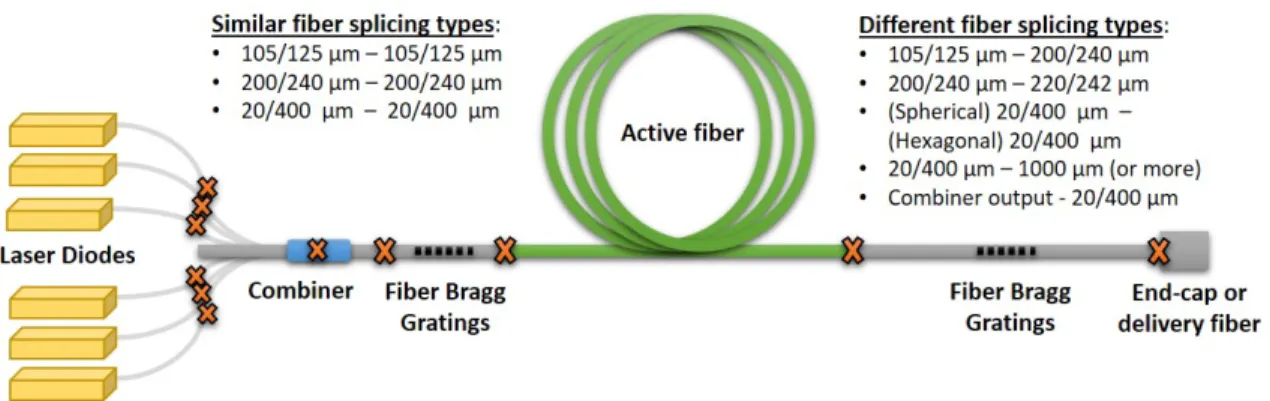
begin with laser diodes at the bottom. Usually, commercial laser diodes come with output fibers having 105 µm, 200 µm, 400 µm core diameter. Then, inte-gration between laser diode fiber output and combiner or FBG input takes place. In Figure 3.5, possible fiber integration types are shown on specific fiber laser oscillator. These possible cladding diameter fiber splice points can be listed as 105/125 µm- 105/125 µm, 200/240 µm- 200/240 µm and 20/400 µm- 20/400 µm. Similar to basic 105/125 µm- 105/125 splicing, 200/240 µm- 200/240 µm multi-mode fiber splicing is shown in Figure 3.6. Basic splicing starts with gap setting position where well cleaved fibers take vis-a-vis positions like shown in Figure 3.6a. Then, alignment of the fibers begins according to their claddings or cores. After finishing the alignment, lasing starts and images of heated fibers
Figure 3.5: Illustration of possible splicing points of fiber having same cladding diameter on the specific concept of high power fiber oscillator.
appear as in Figure 3.6b. At the end of the splicing process, integration point of the fibers are shown as Figure 3.6c with estimated loss and other parameters optionally. Generally, there is white or gray line between integrated multi-mode fibers which comes from the diffusion of doping atoms through the splice point and it is normal for doped multi-mode fibers as long as the line stays in the core region. So, multi-mode fiber splicing is sufficient for high power applications in Figure 3.6c.
Figure 3.6: Splicing of 200 µm core - 240 µm cladding fibers. a) Gap setting position of well cleaved fibers, b) heat distribution of fibers while CO2 lasing and
c) integrated fibers
In order to splice low loss large mode area (LMA) or single mode (SM) fibers, cleaving and splicing parameters should be well optimized. Any cracked or high
angled cleave can cause symptoms like bubbles, curved core or angled core men-tioned in chapter 2.3.3. In Figure 3.7, demonstration of bad splicing between similar 20/400 µm fibers is given. Cleaves, in Figure 3.3b, can cause crater of bubbles at the integration point as in Figure 3.7a.
Figure 3.7: a) Optical microscope image, b) splicer screen-shot of bubble symp-tom at 20/400 µm fiber splicing.
In order to obtain good integration between the fibers, well optimized cleaving and splicing parameters should be used and the the core and the cladding of the fibers should be aligned precisely. A successful splicing between 20/400 µm fibers is shown in Figure 3.8. It is hard to detect the splicing point of fibers with optical microscope image shown in Figure 3.8a. It can be seen that the alignment between the cores of the fibers are almost confined after splicing process in Figure 3.8b.
Figure 3.8: a) Optical microscope image, b) splicer image of successful integration of 20/400 µm splicing.
3.1.2
Splicing of fibers with different cladding diameters
In the previous section, possible fiber splicing points are shown on the illustration of a typical high power fiber laser oscillator concept (Figure 3.5). In this section, CO2 laser splicing of different cladding diameter fibers will be demonstrated. In
Figure 3.9, different fiber splicing types are shown on the same high power laser concept such as 105/125 µm- 200/240 µm, 200/240 µm- 220/242 µm, 200/240 µm- 20/400 µm 20/400 µm- 1000 µm and spherical shape 20/400 µm - hexagonal shape 20/400 µm fibers.
Figure 3.9: Possible integration points between fibers with same or different cladding diameters in a typical high power fiber laser system
These types of integration are usually used for laser diode - combiner input, FBG - Yb-doped active fiber, FBG - end-cap and FBG - QBH delivery fiber optic cable. Depending on the heat in splice processing, there are two types of splicing among different diameter fibers; namely, cold splice and hot splice. In cold splice process, two fibers are joint without changing their shapes and their structure as it is shown in Figure 3.10 a. Cold splices are generally fragile splices but both fibers’ core-cladding diameters and numerical apertures (NA) are conserved. On the other hand, hot splices are strong splices, however, numerical apertures and mode field diameters of both fibers change while melting under a heat source. Illustrations of cold splicing and hot splicing are shown in Figure 3.10.
In Figure 3.11, the splices between 240 µm - 600 µm, 125 µm - 400 µm cold splicing and 125 µm - 600 µm splicing for end-cap applications that will mentioned
Figure 3.10: Illustration of a) cold splicing and b) hot splicing.
at Section 3.2 are shown. Also, Figure 3.11d shows 125 µm - 240 µm hot splicing that works for diode fiber-to-combiner fiber integration applications. 300 µm delivery - 400 µm hexagonal shape active fiber splicing is demonstrated in Figure 3.11e, additionally. In this splice, a high quality laser couples into a delivery fiber with 100/300 µm core/cladding diameter and it is necessary for QBH cable integration to fiber laser. Integration of fibers with different diameters will also be
Figure 3.11: (a) 240µm - 600µm cold splicing. (b) 125µm - 400µm cold splicing. (c) 125µm - 600µm Splicing. (d) 125µm - 240µm hot splicing. (e) 300µm delivery - 400µm hexagonal shape active fiber splicing.
exhibited in section 4.2 as a splice between combiner cleaved end-face and 20/400 µm delivery fiber to complete the combiner fabrication process. Furthermore, another integration point which combines two high power laser sources will be shown in section 5.2. In this splice 20/400 µm fiber output is integrated with 200/240 µm multi-mode fiber as an input of 3x1 combiner.
3.1.3
Low loss integration of core offset fibers
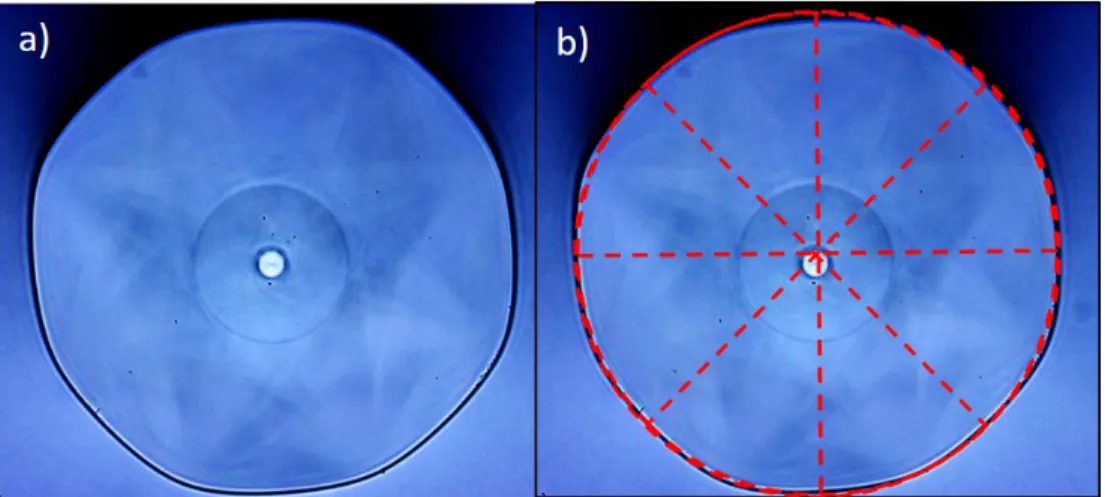
In this section of the thesis, integration of core offset fiber will be shown. While preparing active fiber preforms before drawing the operation, there is a polishing step in order to shape the preforms. Claddings of preforms can be polished as D-shape, hexagonal, elliptical and rectangular. In this polishing step, centering the core is a critical point to get low loss integration. In our institute (Bilkent University, National Nanotechnology Research Center (UNAM)), Y b-doped ac-tive fibers are fabricated in the fiber optic facility by Prof. Mehmet Bayındır group. Unoptimized prototypes of active fibers are demonstrated in Figure 3.12. It is clear that 10 µm core offset from center of fiber is due to uncentered preform polishing. Before obtaining optimized active fibers from Prof. Mehmet Bayındır group, we were able to build a high power fiber laser with in-house fabricated unoptimized active fiber, which will be introduced in Section 4.4.
Figure 3.12: Prototype of in-house drawn Y b-doped active fiber image of a) end-face and b) 10 µm core offset.
Splicing the FBG with an offset-core hexagonal shape active fiber is a critical point in building a high power laser. In Figure 3.13a, gap setting position before alignment of these two fiber is shown. After the lasing process, fibers’ cores are well aligned and integrated to each other (Figure 3.13b). The splicer machine measures the core offset of fibers before and after the splicing process and results of core offset are about 500 nm in total (Figure 3.13c). The cladding of active fiber is 10 µm larger than passive FBG fiber. In addition, the core alignment
Figure 3.13: Splicing process of FBG tile and hexagonal shape active fiber. a) Gap setting position, b) spliced fibers, c) measured core offset before and after splicing
procedure itself causes increment on their claddings offset. Matching not only their cores, but also their claddings is of great importance. Figure 3.14 shows optical microscope images that the cladding of the active fiber is melted on the FBG well enough.
Figure 3.14: Optical microscope images of splicing in a) differential interference contrast (DIC), b) dark field (DF) mode.
3.2
End-cap fabrication with CO
2laser
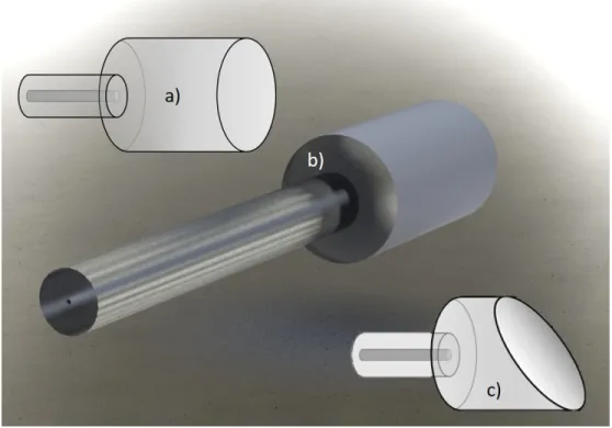
End-cap is a core-less fiber rod which can have a diameter from 125 µm to 3 mm with a length of few millimeters. It is generally used as a component for fiber lasers and amplifiers. According to its length, end-caps expand the beam through the larger diameter of light beams. In Figure 3.15, typical end-cap for LMA fiber is shown.
Figure 3.15: Image of a) end-cap with flat end, b) SolidWorks design of end-cap, c) angled end-cap.
Using end-caps has several advantages. The first advantage is protecting the end-face from optical damages. Optical intensity decreases at the glass-air inter-face, so fiber end-face can be damaged depending on the given optical power and source type (pulsed or continuous). The second advantage is the elimination of Fresnel reflection, fibers or end-caps having flat end results with Fresnel reflection from end-face about 4%. Using angled end-cap, as shown in Figure 3.15c, can eliminate Fresnetel reflection that can result in suppression of parasitic lasing in high-gain fiber amplifiers. Also, for photonic crystal fiber applications end-cap
has advantages in terms of protect these fibers from environmental effects by covering the end-face of the fiber.
In this section, designing, numerical simulation and fabrication steps of end-cap will be shown. Designing of end-end-cap is studied with 3D CAD Design software SolidWorks ( c 2015 Dassault Systemes SolidWorks Corporation, USA) and it is shown in Figure 3.15b.
In order to ensure the length of the end-cap that should be integrated to the fiber end, optical design software Zemax ( 2015 Zemax, LLC All Rights Reserved, Germany) is used and expected results is shown in Figure 3.16. In Figure 3.16a,
Figure 3.16: (a) Ray tracing simulation geometry: single mode source coupled SM fiber and 600 µm end-cap. (b) Simulated beam profile of SM source and end-cap.
ray tracing simulation of integrated SM (9/125 µm core/cladding diameter) fiber with 600 µm coreless end-cap is studied. End-cap length is determined by the NA of the SM fiber output and the point where TIR occurs for the first time. Simulated and expected beam profiles after source output (3.16b) and after end-cap output (3.16c) are also shown. The diameter of the source output beam is increased at the end of the end-cap.
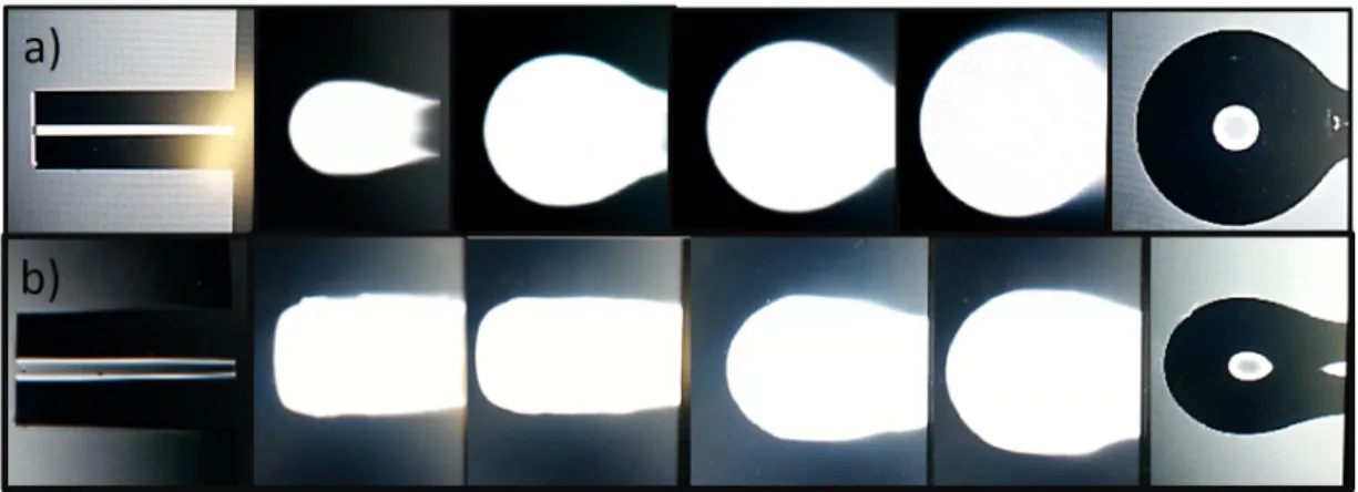
End-cap fabrication starts generally with splicing of fibers having different cladding diameter (Section 3.1.2). In Figure 3.17, typical processing of splicing is demonstrated. Alignment of the glass rod and the fiber about the center is critical to obtain unscattered beam profiles. After the alignment process, CO2
Figure 3.17: Splicing process: (a) starting to melt 600m and 9/125m fibers with CO2 laser, (b) melting and splicing of two fibers, (c) after splicing and proof test.
(d) Optical microscope image of the splicing point of the end-cap.
in Figure 3.17a and b. There is also different size (”400-125” and ”2000-125”)
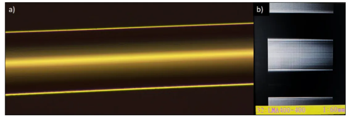
Figure 3.18: Splicing of a) 2000 µm rod and 125 µm SM fiber b) 400 µm MM fiber and 125 µm SM fiber
end-cap splicing in Figure 3.18. In this Figure, 2000 µm rod and 125 µm SM fiber are spliced to each other, also 400 µm MM fiber is spliced to 125 µm SM fiber. In this thesis, we spliced the rods with different cladding diameters with 125 µm SM fiber. In the future, we will integrate end-caps to LMA high power laser outputs in order to protect them from end-face damages.
3.3
Ball lens fabrication with CO
2laser
Ball lens is an optical component which is spherically shaped with a CO2 laser
ra-diation. They are generally used to collimate or focus light which comes from the fiber output. Ball lenses are utilized for increasing light coupling between fibers,