LSB Image Steganography Based on
Blocks Matrix Determinant Method
Danish Shehzad*, Tamer Dag
Computer Engineering Department, Kadir Has University, Istanbul, Turkey [Email: [email protected], [email protected]]
*Corresponding author: Danish Shehzad
Received June 6, 2018; revised September 18, 2018; accepted December 22, 2018; published July 31, 2019
Abstract
Image steganography is one of the key types of steganography where a message to be sent is hidden inside the cover image. The most commonly used techniques for image steganography rely on LSB steganography. In this paper, a novel image steganography technique based on blocks matrix determinant method is proposed. Under this method, a cover image is divided into blocks of size 2 x 2 pixels and the determinant of each block is calculated. The comparison of the determinant values and corresponding data bits yields a delicate way for the embedment of data bits. The main aim of the proposed technique is to ensure concealment of secret data inside an image without affecting the cover image quality. When the proposed steganography method is compared with other existing LSB steganography methods, it is observed that it not only provides higher PSNR, lower MSE but also guarantees better quality of the stego image.
Keywords: Image Steganography, Least Significant Bits (LSB), Matrix Determinant Steganography (MDS), Peak Signal to Noise Ratio (PSNR)
1. Introduction
I
n the era of advancements in the field of communication technology, the security of data is one of the major research concerns. There are many cryptographic methodologies that are adopted to secure secret information transfer. Steganography is based on concealment of secret data in another type of information. Steganography is derived from two Greek words; ‘steganos’ which means covered and ‘graptos’ which means writing. Steganography works differently from cryptography by hiding secret information inside cover of file formats like image, video, audio, and text [1, 2]. It benefits through protected communication by not allowing unauthorized access to important and secret data. Image steganography relies on three components: 1) the cover image which functions to conceal information; 2) the secret information; 3) and the stego image having concealed data. In spatial domain, least significant bits (LSB) steganography is the most frequently used image steganography. There are various LSB steganography techniques in literature [3]. All the steganographic techniques under use have their own benefits and weaknesses specifically measured on the basis of imperceptibility, embedding capacity and robustness. Human visual system (HVS) is vulnerable to light variations; it is hard to distinguish between similar colors. For instance, black color has 0 pixel value. Human eye is unable to distinguish between black colors for pixel values 0 to 15. These facts made scientists utilize the limitation of HVS to store secret information in LSBs [4].The proposed technique is 1LSB technique and outcome of this steganography technique shows that suggested methodology has better quality of stego image and improves security of secret information. LSB steganographic techniques are commonly evaluated by image performance metrics such as peak signal to noise ratio (PSNR), Universal Image Quality Index (UIQI) and Mean Square Error (MSE). In the proposed image steganography based on blocks matrix determinant (MDS), for the valuation of prominence of proposed technique, we considered different attributes suggested by [6-8].
This paper is arranged in five different sections: Section 2 focuses on literature review, while in section 3 the methodology of proposed technique is explained. In section 4, metrics used for the assessment of stego image quality are described. In section 5, experimental results are explained where both quantitative and qualitative analysis is done for showing the significance of proposed methodology.
2. Background
Image steganography can be categorized into two main domains depending upon data embedding mechanism, mainly as spatial domain image steganography and frequency domain image steganography [5, 6]. LSB is the most frequently used spatial domain image steganography technique in which data is embedded inside least significant bits of image pixels. Various key types of existing LSB steganography techniques are discussed below.
2.1. LSB in GIF Images
Graphic Interchange Format (GIF) is a palette based image in which alpha channel is used to store colors or a color lookup table. In this method, information is concealed in the least significant bits of GIF images. The major problem of this method is limited payload and its vulnerability to visual and statistical threats [7].
2.2. Difference Expansion LSB Technique
In this technique LSB embedding focuses on using difference expansion technique which utilizes redundancy in digital data to embed single bit of message in two bits of cover image pixels [8]. This method puts less data bits in cover image and do not generate a high quality stego images.
2.3. Hiding behind the Corners
Hiding behind corners LSB technique is based on considering original data to discover the suitable hiding areas in cover image and secret message bits are concealed in corners [9]. The major shortcoming of this method is that its embedding capability is very small.
2.4. Edge-based LSB Techniques
This technique focuses on hiding data in the edges of an image. Data is hidden in those patches of image where value of pixels differ from their neighboring pixels i.e. edges and corners where the significance of derivative is elevated [10]. The benefit of this method is that pixel modifications at the corners of image are not taken into consideration by attackers. The drawback is same that it has short embedding capability. Another edge based LSB method is focused on using difference of two pixel values. In this method, edges hide more bits than even areas of the image. The data embedding capability of this technique is fairly more, but it is less secure [11].
2.5. Pixel Value Differencing and Modulus LSB Technique
This method relies on using difference and modulus function to secure data by changing the remainder [12]. Pixel value differencing and modulus LSB technique embeds a smaller amount of data in images.
2.6. Image Interpolation LSB Technique
Image interpolation technique is used to make information secure in the disturbance area [19]. This technique hides additional data in rough areas of image than in smooth regions. Data is not fully secure in this method. Data can be retrieved from the file [13].
2.7. Neighborhood Pixel Information Technique
This method embeds secrets data bits in cover image pixels based on values of neighboring pixels. Three neighborhood methods are used for embedding data; in-Four Neighborhood Method, Diagonal Neighborhood Method and Eight Neighborhood Method. Embedding capacity of this method is high yet secret data is deformed, therefore retrieval is difficult if stego image quality is altered during information transfer [14].
2.8. Threshold Based Image Steganography Technique
Threshold based steganography is a technique that scans cover image for color intensities and distinguishes image pixels based on their grey or color level. Image pixels are divided into four categories based on their pixels and after the classifications of pixels data bits from secret message are embedded into the pixels according to their category [15].
2.9. Image Steganography Using Similarity of Bits Pairs
In this method pair wise matching of pixels is used to hide information. In this technique two bits are embedded inside each pixel. The pixels bits are compared with secret data bits pairs, if any of the pixel pair match with data bits number of pixel pair is stored in least two
significant bits. If none of the pixels bits are match than data bits are stored in 0th pair and pair number is stored in 2LSBs [16].
3. LSB Image Steganography Based on Blocks Matrix Determinant
Method
The main purpose of the proposed MDS technique is to hide secret data while ensuring minimal effect on the cover image quality. The process of embedding data to the cover image and extracting data from the stego image is explained below.
3.1 Encoding Process for MDS
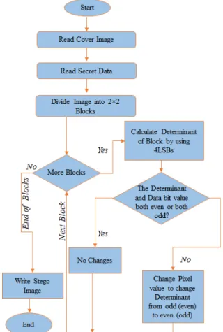
The encoding process for the LSB image steganography based on blocks matrix determinant method follows the steps described below:
• If the cover image is a color image, then it is divided into RGB channels and read. If the cover image is a monochrome or a greyscale image, then only the single grey channel is read.
• The cover image is divided into blocks of size 2 x 2 pixels.
• For every block, the decimal value of the four LSBs of the four pixels forming the block is calculated.
• By using the decimal values calculated above, the determinant of each block is calculated.
• Since one data bit is inserted into one block, 𝑖𝑖𝑡𝑡ℎ data bit from data stream will be inserted virtually into the 𝑖𝑖𝑡𝑡ℎ block of the cover image.
• Based on the value of the determinant of the 𝑖𝑖𝑡𝑡ℎ block and 𝑖𝑖𝑡𝑡ℎ data bit, there exists four different cases of encoding.
1. The 𝑖𝑖𝑡𝑡ℎ block determinant is even and the 𝑖𝑖𝑡𝑡ℎ bit of secret data is 0. 2. The 𝑖𝑖𝑡𝑡ℎ block determinant is even and the 𝑖𝑖𝑡𝑡ℎ bit of secret data is 1. 3. The 𝑖𝑖𝑡𝑡ℎ block determinant is odd and the 𝑖𝑖𝑡𝑡ℎ bit of secret data is 0. 4. The 𝑖𝑖𝑡𝑡ℎ block determinant is odd and the 𝑖𝑖𝑡𝑡ℎ bit of secret data is 1.
• If the determinant and the data bit to be inserted are both odd or both even, then there is no need for modification of any pixel in the block. Thus, for case 1 or case 4 above, no changes are made in the pixel values of the block. When case 2 occurs, by changing pixel values of the block, the block determinant will be made odd. When case 3 occurs, by changing pixel values of the block, the block determinant will be made even.
The process of encoding is also illustrated as a flowchart in Fig. 1.
The method of changing the pixel values of a block and to convert a determinant from odd to even or from even to odd is explained as follows:
Let 𝐴𝐴 = �𝑎𝑎 𝑏𝑏
𝑐𝑐 𝑑𝑑� be a block of the cover image with the element values calculated from the 4LSBs of the corresponding pixels. The determinant of the block A can be calculated as shown below:
|𝐴𝐴| = �𝑎𝑎 𝑏𝑏
Fig. 1. The flowchart for the encoding process of MDS
Suppose E represents an even number and O represents an odd number. Based on the elements of the block A, there are sixteen possible cases for which |𝐴𝐴| can generate even or odd as listed below: 1. 𝐼𝐼𝐼𝐼 𝐴𝐴 = �𝐸𝐸 𝐸𝐸𝐸𝐸 𝐸𝐸� , 𝑡𝑡ℎ𝑒𝑒𝑒𝑒 |𝐴𝐴| = 𝐸𝐸 9. 𝐼𝐼𝐼𝐼 𝐴𝐴 = �𝐸𝐸 𝐸𝐸𝐸𝐸 𝑂𝑂� , 𝑡𝑡ℎ𝑒𝑒𝑒𝑒 |𝐴𝐴| = 𝐸𝐸 2. 𝐼𝐼𝐼𝐼 𝐴𝐴 = �𝑂𝑂 𝐸𝐸𝐸𝐸 𝐸𝐸� , 𝑡𝑡ℎ𝑒𝑒𝑒𝑒 |𝐴𝐴| = 𝐸𝐸 10. 𝐼𝐼𝐼𝐼 𝐴𝐴 = �𝑂𝑂 𝐸𝐸𝐸𝐸 𝑂𝑂� , 𝑡𝑡ℎ𝑒𝑒𝑒𝑒 |𝐴𝐴| = 𝑂𝑂 3. 𝐼𝐼𝐼𝐼 𝐴𝐴 = �𝐸𝐸 𝑂𝑂𝐸𝐸 𝐸𝐸� , 𝑡𝑡ℎ𝑒𝑒𝑒𝑒 |𝐴𝐴| = 𝐸𝐸 4. 𝐼𝐼𝐼𝐼 𝐴𝐴 = �𝑂𝑂 𝑂𝑂𝐸𝐸 𝐸𝐸� , 𝑡𝑡ℎ𝑒𝑒𝑒𝑒 |𝐴𝐴| = 𝐸𝐸 5. 𝐼𝐼𝐼𝐼 𝐴𝐴 = �𝐸𝐸 𝐸𝐸𝑂𝑂 𝐸𝐸� , 𝑡𝑡ℎ𝑒𝑒𝑒𝑒 |𝐴𝐴| = 𝐸𝐸 6. 𝐼𝐼𝐼𝐼 𝐴𝐴 = �𝑂𝑂 𝐸𝐸𝑂𝑂 𝐸𝐸� , 𝑡𝑡ℎ𝑒𝑒𝑒𝑒 |𝐴𝐴| = 𝐸𝐸 7. 𝐼𝐼𝐼𝐼 𝐴𝐴 = �𝐸𝐸 𝑂𝑂𝑂𝑂 𝐸𝐸� , 𝑡𝑡ℎ𝑒𝑒𝑒𝑒 |𝐴𝐴| = 𝑂𝑂 8. 𝐼𝐼𝐼𝐼 𝐴𝐴 = �𝑂𝑂 𝑂𝑂𝑂𝑂 𝐸𝐸� , 𝑡𝑡ℎ𝑒𝑒𝑒𝑒 |𝐴𝐴| = 𝑂𝑂 11. 𝐼𝐼𝐼𝐼 𝐴𝐴 = �𝐸𝐸 𝑂𝑂𝐸𝐸 𝑂𝑂� , 𝑡𝑡ℎ𝑒𝑒𝑒𝑒 |𝐴𝐴| = 𝐸𝐸 12. 𝐼𝐼𝐼𝐼 𝐴𝐴 = �𝑂𝑂 𝑂𝑂𝐸𝐸 𝑂𝑂� , 𝑡𝑡ℎ𝑒𝑒𝑒𝑒 |𝐴𝐴| = 𝑂𝑂 13. 𝐼𝐼𝐼𝐼 𝐴𝐴 = �𝐸𝐸 𝐸𝐸𝑂𝑂 𝑂𝑂� , 𝑡𝑡ℎ𝑒𝑒𝑒𝑒 |𝐴𝐴| = 𝐸𝐸 14. 𝐼𝐼𝐼𝐼 𝐴𝐴 = �𝑂𝑂 𝐸𝐸𝑂𝑂 𝑂𝑂� , 𝑡𝑡ℎ𝑒𝑒𝑒𝑒 |𝐴𝐴| = 𝑂𝑂 15. 𝐼𝐼𝐼𝐼 𝐴𝐴 = �𝐸𝐸 𝑂𝑂𝑂𝑂 𝑂𝑂� , 𝑡𝑡ℎ𝑒𝑒𝑒𝑒 |𝐴𝐴| = 0 16. 𝐼𝐼𝐼𝐼 𝐴𝐴 = �𝑂𝑂 𝑂𝑂𝑂𝑂 𝑂𝑂� , 𝑡𝑡ℎ𝑒𝑒𝑒𝑒 |𝐴𝐴| = 𝐸𝐸 (5)
Therefore, if the determinant of the block needs to be converted from even to odd or from odd to even, then a combination from Eq. 5 can be used. There are sixteen different combinations which result in either even or odd determinants. Out of sixteen, there are ten combinations which result into an odd determinant value and six combinations generate even determinant value.
To illustrate with the help of example, let us consider if the block is similar as case 6 of Eq. 5, its determinant is even. But if the data bit to be inserted is 1, then the determinant of the block should be converted into odd. This can be done by modifying the block to a similar form as in case 8 or 14 of Eq. 5. This only requires a single pixel’s LSB modification inside the block. Thus, the LSB values of the pixels corresponding to matrix element c in case 8 or d in case 14 would be inverted to make the determinant odd. The selection of the case for the modification is kept random when there are multiple options ensuring minimal changes. The reliability of this technique is increased as the alteration in pixels’ value of the resultant block is also kept at random. In addition, a change in pixel value is kept random as +1 or -1 which makes it more complex and challenging to break. This data concealment method results in a secure and a reliable steganographic mechanism which helps to improve the complexity of MDS technique and makes it more difficult for the intruders to notice the concealed data or to detect the original data from stego images.
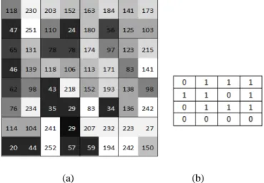
The encoding method is elaborated with the help of following example. Let us consider an 8 x 8 monochrome cover image with the pixel values as shown in Fig. 2.a and the data to be embedded into the cover image is shown in Fig. 2.b. The cover image is divided into blocks of size 2 x 2 pixels as shown in Fig. 2.a. The process of embedding secret message bits for two different blocks, first block (block (1,1)) and third block (block (1,3)) respectively are as follows:
(a) (b)
Fig. 2. Data Encoding Example: a) Cover Image b) Secret Data Bits
-
• The pixel values for the first block are 118, 230, 47 and 251. When represented in binary these values are 01110110, 11100110, 00101111 and 11111011 respectively. Thus, the block matrix for the first block is obtained by mining the 4LSBs from each pixel and represented as shown in Eq. 6.
𝐴𝐴 = � 615 11�6 (6)
The determinant for this block is even, as shown in Eq. 7 below:
|𝐴𝐴| = � 6 6
15 11� = 6 × 11 − 6 × 15 = −24 (7)
As the determinant of the block is even and first secret data bit to be inserted is a 0, no changes will occur in this block. As a consequence, the data bit into first block is
concealed into the cover image without changing a single pixel value of the block. Thus, for this block cover image and stego image pixel values will be the same.
• The pixel values for the third block are 163, 184, 180 and 56. When represented in binary these values are 10100011, 10111000, 10110100, 00111000 respectively. Thus, the block matrix for the third block is obtained by mining the 4LSBs from each pixel and represented as shown in Eq. 8.
𝐴𝐴 = �3 8
4 8� (8)
The determinant for this block is even, as shown in Eq. 9 below:
|𝐴𝐴| = �3 8
4 8� = 3 × 8 − 8 × 4 = −8 (9)
For the third block, secret data bit to be inserted is 1 but determinant is even. The form of the block matches with case 2 of Eq. 5. To make the determinant odd, this block would be converted into case 10 of Eq. 5 by changing only one bit in the block. If the LSB of the last pixel is inverted, the block matrix of the third block will take the form as shown in Eq. 10 below:
𝐴𝐴 = �3 84 9� (10)
Now, the determinant for this block is odd, as shown in Eq. 11, thus giving the information that the inserted data bit into this block is a 1.
|𝐴𝐴| = �3 8
4 9� = 3 × 9 − 8 × 4 = −5 (11)
In the stego image, the pixel values for the third block will be 163, 184, 180 and 57. To conclude the above example, when data bit and block determinant values are in accordance with each other no change is required but still one data bit is embedded in the block and when they are not in accordance with each other; change is made in block in a logical and calculated manner which ensure minimal change in pixels during data encoding. Thus, at larger scale it can be anticipated that in MDS to conceal a data bit in a single block the chance of modifying pixel’s value is 50%, resulting in minimal effect and better quality of stego image.
3.2 Decoding Process for MDS
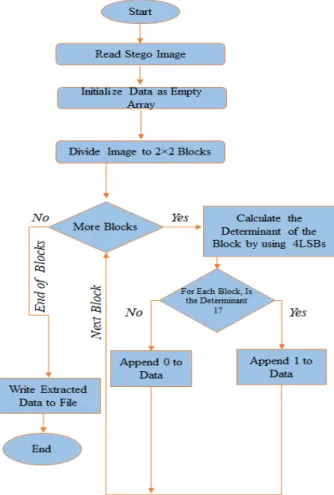
Once the stego image is received, the decoding process for the LSB image steganography based on blocks matrix determinant method follows the steps described below:
• If the stego image is a color image, then it is divided into RGB channels and read. If the stego image is a monochrome or a gray scale image, then only the single grey channel is read.
• The stego image is divided into blocks of size 2 x 2 pixels.
• For every block in the stego image, the decimal value of the four LSBs of the four pixels forming the block is calculated.
• By using the decimal values calculated above, the determinant of each block is calculated, and data bits are extracted.
1. If the 𝑖𝑖𝑡𝑡ℎ block determinant is even, then the 𝑖𝑖𝑡𝑡ℎ bit of the secret data is 0. 2. If the 𝑖𝑖𝑡𝑡ℎ block determinant is odd, then the 𝑖𝑖𝑡𝑡ℎ bit of secret data is 1. • All extracted data bits are concatenated to form the secret data.
The process of decoding is also illustrated in Fig. 3.
Fig. 3. The flowchart for the decoding process of MDS
4. Image Quality Assessment Metrics
A steganographic technique is evaluated based on three main features; payload, imperceptibility and robustness. A technique is considered best if it provides high data hiding capacity, high level of imperceptibility and is robust against attacks but the most significant factor is its property to remain undetectable. There always exists a tradeoff between these three factors [17].
4.1 Payload
The payload represents the total amount of data embedded inside a stego image in bits [18]. It can be calculated by using the following equation:
Payload = ∑ ∑Mj=1 Nk=1Bits �𝑥𝑥𝑗𝑗,𝑘𝑘′ � (1) where j, k represents pixels location and 𝑥𝑥𝑗𝑗,𝑘𝑘′ gives amount of data hidden in stego image.
4.2 Imperceptibility
Data hiding capacity and imperceptibility are directly proportional to each other. The higher the fidelity of a stego image, the better is the imperceptibility and imperceptibility is satisfied when there is minimal difference between original and stego image. Imperceptibility of a method is determined based on image quality metrics which mainly include PSNR, MSE and UIQI [18]. For the proposed method, these key parameters are tested to certify the suitability of the proposed method over existing steganography methods.
MSE is used as common distortion measure to access the quality of images [17]. MSE of a stego image is calculated by taking the average of squared intensity of input image and stego image as shown by the following equation:
MSE = 1
MN∑ ∑ (xMj=1 Nk=1 j,k− x′j,k)2 (2) where N is number of rows and M is number of columns which represent dimensions of image, j and k are image coordinates. 𝑥𝑥𝑗𝑗,𝑘𝑘′ is generated stego image and 𝑥𝑥𝑗𝑗,𝑘𝑘 is the original cover image. UIQI is an indicator that shows the quality of an image after the application of the steganography process. Original image and stego images are compared based on luminance, structure comparison and contrast. 1 is the maximum value for UIQI which shows no change in image or original image. The most common parameter used for the evaluation of an image quality through an objective manner is the PSNR. It is a mathematical measure for identifying image quality based on the pixel difference between the original and the stego images [19]. The value of PSNR is calculated by using the equation below:
PSNR = 10 Log10C2max
MSE (3)
where MSE denotes mean squared error and Cmax holds maximum value in the image.
4.3 Robustness
Robustness is a property of harness of eliminating secret information from stego image. Transform domain techniques transform image into another domain by using DWT, DFT and DCT to hide the secret information [5]. Transform domain techniques are more robust against statistical attacks [20, 21]. Spatial domain techniques embed data into image directly, these techniques are not robust enough against statistical attacks like RS-analysis, Chi-square attack etc. Spatial domain steganography techniques are examined via stegnalysis and the main aim of stegnalysis is detection of secret information from cover image [22]. The most commonly used stegnalysis techniques include visual stegnalysis, histogram analysis, higher order statistics (RS) and two-fold statistical techniques for images by using spatial correlations. For the stegnalysis of the proposed method in this paper, visual detection and histogram analysis are performed.
5. Experimental Results
The proposed technique along with other existing techniques is implemented in MATLAB R2016a on Intel core i5 with 4 cores and using 8 GB RAM. Experiments are performed on fifty standard images; and the results for some of the 512 x 512 pixels and 256 x 256 pixels standard images are presented here for the experimental analysis of the proposed technique. These images are taken from database “The USC-SIPI Image Database Volume 3: Miscellaneous” [23]. The proposed technique is first compared with existing LSB image steganography techniques, where it ensures the high security while having limited data hiding capacity. Secondly to illustrate the security improvement, MDS is compared with
1LSB steganography techniques. Fixed amount of data is hidden in standard images. When compared, MDS shows highest PSNR and lowest MSE depicting the prominence of the proposed technique over other 1LSB steganography techniques. In qualitative analysis, section histogram analysis is done to verify the image quality of stego image generated by MDS data embedding. The following sub-sections illustrate the experimental results.
5.1 Quantitative Analysis
The quantitative results are calculated based on standard image performance metrics described in section 4. For analysis of different LSB steganography techniques two color images Lena and Baboon images are used, whereas from grey scale images Lena grey and Baboon grey images are selected. The payload of MDS is defined as one bit per block since one bit data is stored per four pixels. As a result, for 256 x 256, 512 x 512 and 1024 x 1024 sized color images, maximum data hiding capacity using MDS is 8 KB, 24 KB and 96 KB respectively. PSNR values, which indicate the peak signal to noise ratio, under MDS are higher when compared to other methods, certifying the high quality of the stego images. The results calculated for MSE under MDS are lower when compared to other LSB image steganography methods. After the application of MDS encoding process with maximum payload for the above mentioned images the value of UIQI is calculated to be 0.99 which indicates that data embedding has minimal effect on pixel values and data is concealed without compromising on image quality.
Table 1. Comparison of MDS stego Baboon and Lena gray (512 x 512 pixels sized) images with existing methods.
Method Baboon Gray Lena Gray
MSE PSNR (dB) Payload (bits) MSE PSNR (dB) Payload (bits)
[15] 2,33 44,38 410.636 2,84 43,64 433.224 [16] 21,10 34,92 524,288 19,82 35,19 524.288 [25] 10,54 37,9 56.291 4,30 41,79 50.960 [26] 32,51 33,01 916.010 15,31 36,28 837.332 [27] 81,86 29 1.024 65,02 30 1.024 [28] 34,12 32,8 14.916 14,22 36,6 85.507 [29] 10,30 38 15.176 10,30 38 74.600 [30] 15,27 36,29 886.516 11,22 37,63 809.966 MDS 0,12 57,19 65.536 0,12 56,98 65.536
Table 1 shows the results comparison between the proposed method and other LSB image steganography methods in the literature for Baboon Gray and Lena Gray stego images. When MDS generated results are compared to the other LSB steganography methods for gray images, MDS provides much better data security having highest PSNR and lowest MSE but payload of MDS is lower from some of them. Thus, limitation of this technique is in terms of its limited payload, but it is most appropriate when high security is required for steganographic purposes.
Table 2. Comparison of MDS stego Baboon and Lena colored (512 x 512 pixels sized) images with existing methods.
Method
Baboon Colored Lena Colored
MSE PSNR (dB) Payload (bits) MSE PSNR (dB) Payload (bits)
[15] 1,22 47,15 1.329.318 3,24 42,32 1.355.199
[16] 9,54 38,36 1.572.864 9,06 38,57 1.572.864
[31] 7,12 39,6 1.156.000 7,19 39,56 1.156.000
[32] 19,51 35,22 2.877.658 5,61 46,64 2.297.680
MDS 0,09 58,19 196.608 0,09 57,49 196.608
Table 2 shows the results comparison for Baboon and Lena stego color images. When compared with other LSB methods, the MSE is the lowest for MDS stego color images. In addition, the difference from the original image is the lowest resulting in highest PSNR values.
To illustrate the effectiveness of MDS, experiments are also conducted by embedding fixed size data in different 1LSB image steganography techniques. A secret data of 6 KB is embedded in four different color images Baboon, Lena, Building and House of size 256 x 256 pixels and the results for stego images are compared with only 1LSB steganography techniques. For the evaluation of MDS encoding mechanism, when PSNRs are compared; MDS has the highest PSNR as shown in Table 3.
Table 3. Comparison of MDS with 1LSB methods based on PSNR (dB) by hiding 6KB data in ( 256 x 256 pixels sized) color images
Image Classic LSB Method [33] [34] [35] [36] [22] MDS Baboon 51,46 49,13 46,53 40,06 49,37 54,17 58,26 Lena 45,61 45,61 49,20 40,26 45,61 52,38 57,55 Building 49,84 46,72 46,82 40,30 48,34 52,37 57,49 House 51,48 51,48 47,68 40,27 51,47 52,37 56,84
Results for PSNR are shown graphically for Building, House, Baboon and Lena color images in Fig. 4.
Fig. 4. 1LSB techniques comparison based on PSNR (dB) by hiding 6KB data in (256 x 256 pixels sized) color images
The MSE values are also calculated after hiding 6 KB of data in these images. Minimal values for MSE show that MDS produces minimal changes/error in stego images as compared to other 1LSB images steganography methods as shown in Table 4.
Table 4. Comparison of MDS with 1LSB methods based on MSE by hiding 6KB data in (256 x 256 pixels sized) color images
Image Classic LSB Method [33] [34] [35] [36] [22] MDS
Baboon 0,46 0,79 1,45 6,41 0,75 0,25 0,097
Lena 1,78 1,78 0,78 6,12 1,79 0,38 0,114
Building 0,67 1,38 1,35 6,07 0,95 0,38 0,116
House 0,42 0,46 1,11 6,11 0,46 0,38 0,135
The results for PSNR and MSE certify high security and stego image quality prominence of MDS as compared to existing 1LSB image steganography techniques.
5.2 Qualitative Analysis
In this subsection, a qualitative analysis is presented for MDS. Histogram analysis is one of the significant types of stegnalysis where pixel by pixel comparison depicts the quality of a steganographic technique. The qualitative comparison in this section shows that for the original image and the stego image pixel values are almost the same and the distortion is not noticeable depicting the high quality of stego images. The comparison of original and stego images and their histograms are shown in Fig. 5-8.
Fig. 5. Qualitative comparison for Baboon color cover image vs. stego image (with size 512 x 512 pixels) and their histogram
Fig. 6. Qualitative comparison for Lena color cover image vs. stego image (with size 512 x 512 pixels) and their histogram
Fig. 5 and 6 shows the comparison between original and stego 512 x 512 pixels sized Baboon and Lena colored images. 24 KB data is stored inside original images using MDS encoding method. For the Baboon stego image generated by application of MDS encoding method PSNR of 58.19 dB and MSE of 0.09 is calculated. Whereas, for Lena stego image PSNR of 57.49 dB and MSE of 0.09 is noticed. The visual comparison between images and pixel by pixel comparison for original images and stego images using histogram shows that data embedment in these colored images do not have any noticeable affect the pixel values of original cover images confirming the quality of MDS method.
Fig. 7. Qualitative comparison for Baboon gray cover image vs. stego image (with size 512 x 512 pixels) and their histogram
Fig. 8. Qualitative comparison for Lena gray cover image vs. stego image (with size 512 x 512 pixels) and their histogram
Histogram analysis are also performed on 512 x 512 pixels sized Baboon and Lena gray images as shown in Fig. 7 and 8. Data of 8KB is embedded in these images. PSNR of 57.19 dB and 0.12 MSE are noted for Baboon stego image, while PSNR for Lena stego image is 56.98 dB and MSE calculated is 0.12. Histogram comparison shows almost no change in the pixel values before and after data embedding in grey images. Thus, proposed method MDS is more secure, have minimal effect on cover images and reliable than other prevailing LSB image steganography techniques.
Conclusion
In this paper a novel LSB image steganography technique based on blocks matrix determinant is proposed. This technique is 1 LSB and is more secure and reliable than other prevailing techniques. In this technique image is divided into blocks of 2 x 2 and 4LSBs are chosen. These target bits are converted into decimal values; determinant for every block is
calculated. If the data bit to be hidden is 0 and the determinant of the block is even or if the data bit is 1 and the determinant of the block is odd then no change is required. But if the data bit is 0 and determinant of block is odd or data bit is 0 and determinant is even then 1 bit modification is done. This allows hiding data with minimal modifications in pixel values. The results exhibit that this technique ensures high security level along with exploiting efficient methodology for its execution.
References
[1] A.S Pandit, S.R Khope & F.Student, “Review on Image Steganography,” International
Journal of Engineering Science, 6115, 2016.
[2] M. Hussain, A.W Wahab, Y.I.B Idris & K.H, “Jung, Image steganography in spatial domain: A survey,” Signal Processing: Image Communication, vol. 65, pp. 46-66, 2018.
Article (CrossRef Link).
[3] A. Cheddad, J. Condell, K. Curran & P. Mc Kevitt, “Digital image steganography: Survey and analysis of current methods,” Signal processing, 90(3), 727-752, 2015.Article (CrossRef Link).
[4] M.S. Subhedar & V.H. Mankar, “Current Status and Key issues in Image Steganography: A survey,” Computer science review, 13-14, 95-113, 2014.Article (CrossRef Link).
[5] S. Sharma & U. Kumar, “Review of Transform Domain Techniques for Image Steganography,”
International Journal of Science and Research, 2(2), 1, 2015.
[6] J.-M. Guo and T.-N. Le, “Secret communication using JPEG double compression,” IEEE
Signal Processing Letters, vol. 17, no. 10, pp. 879-882, 2010.Article (CrossRef Link).
[7] W. Bender, D. Gruhl, N. Morimoto & A. Lu, “Techniques for data hiding,” IBM systems
journal, vol. 35, no. 3.5, pp. 313-336, 1996.Article (CrossRef Link).
[8] J. Tian, “Reversible data embedding using a difference expansion,” IEEE Trans. Circuits Syst.
Video Techn., vol. 13, no. 8, pp. 890-896, 2003.Article (CrossRef Link).
[9] K. Hempstalk, “Hiding behind corners: Using edges in images for better steganography,” in
Proc. of the Computing Women’s Congress, Hamilton, New Zealand, pp. 11-19, 2006.
[10] K. M. Singh, L. S. Singh, A. B. Singh & K. S. Devi, “Hiding secret message in edges of the
image,” in Proc. of International Conference on Information and Communication Technology, 2007.Article (CrossRef Link).
[11] C.-H. Yang, C.-Y. Weng, S.-J. Wang & H.-M. Sun, “Adaptive data hiding in edge areas of
images with spatial LSB domain systems,” IEEE Transactions on Information Forensics and
Security, vol. 3, no.3, pp. 488-497, 2008.Article (CrossRef Link).
[12] W. Luo, F. Huang, and J. Huang, “Edge adaptive image steganography based on LSB matching
revisited,” IEEE Transactions on Information Forensics and Security, vol. 5, no. 2, pp. 201-214, 2010.Article (CrossRef Link).
[13] L. Luo, Z. Chen, M. Chen, X. Zeng, and Z. Xiong, “Reversible image watermarking using
interpolation technique,” IEEE Transactions on Information Forensics and Security, vol. 5, no.1, pp. 187-193, 2010.Article (CrossRef Link).
[14] M. Hossain, S. Al-Haque, and F. Sharmin, “Variable rate steganography in grayscale digital
images using neighborhood pixel information,” International Arab Journal of Information
Technology, vol. 7, pp. 34-38, 2010.
[15] Z. Khan, M. Shah, M. Naeem, T, “Mahmood, S.N.A. Khan, N. Amin, D. Shahzad, Threshold
based Steganography: A novel technique for improved payload and SNR,” International Arab
Journal of Information Technology, vol. 13, no 4, 2016.
[16] D. Shehzad & T. Dag, “A novel image steganography technique based on similarity of bits
pairs,” in Proc. of Control and System Graduate Research Colloquium (ICSGRC), IEEE
8th (pp. 99-104). IEEE, 2017.Article (CrossRef Link).
[17] A.B Dehkordi, S. Esfahani, & A.N. Avanaki, “Robust LSB watermarking optimized for local
structural similarity,” in Proc. of (ICEE), 19th Iranian Conference on Electrical Engineering,
[18] P. Moulin & M. K. Mihcak, “A framework for evaluating the data-hiding capacity of image sources,” IEEE Transactions on Image Processing, 11(9), 1029-1042, 2002.
Article (CrossRef Link).
[19] D. Neeta, K. Snehal & D. Jacobs, “Implementation of LSB steganography and its evaluation
for various bits,” in Proc. of 1st International Conference on Digital Information Management, IEEE, pp. 173-178, 2006. Article (CrossRef Link).
[20] S. Bhattacharyya & G. Sanyal, “A robust image steganography using DWT difference
modulation (DWTDM),” International Journal of Computer Network and Information
Security, 4(7), 27, 2012. Article (CrossRef Link).
[21] Y. Zhang, C. Qin, W. Zhang, W., Liu, F., & Luo, X, “On the fault-tolerant performance for a
class of robust image steganography,” Signal Processing, 146, 99-111, 2018. Article (CrossRef Link).
[22] M. Khan, et al., “A secure method for color image steganography using gray-level modification
and multi-level encryption,” TIIS, 9(5), 1938-1962, 2015. Article (CrossRef Link).
[23] A. Weber, “The USC-SIPI Image Database,” Miscellaneous, Vol. 3.
[24] D. Wu and W. Tsai, “A steganographic method for images by pixel-value differencing,”
Pattern Recognition Letters, vol. 24, no. 9-10, pp. 1613-1626, 2003. Article (CrossRef Link).
[25] C. Yang, C. Weng, S. Wang and H. Sun, “Adaptive data hiding in edge areas of images with
spatial LSB domain systems,” IEEE Transaction on Information Forensics Security, vol. 3, no. 3, pp. 488-497, 2008. Article (CrossRef Link).
[26] C. Vleeschouwer, J. Delaigle, and B. Macq, “Circular interpretation on histogram for reversible
watermarking,” in Proc. of the 4th IEEE International Workshop on Multimedia Signal
Processing, Cannes, pp. 345-350, 2001. Article (CrossRef Link).
[27] M. Goljan, J. Fridrich and R. Du, “Distortion free data embedding for Image,” in Proc. of the
4th Information Hiding Workshop, Pittsburgh, pp. 27-41, 2001. Article (CrossRef Link).
[28] G. Xuan, J. Zhu, J. Chen, Y. Shi, Z. Ni and W. Su, “Distortionless data hiding based on integer
wavelet transform,” IEEE Letters, vol. 38, no. 25, pp. 646-1648, 2002. Article (CrossRef Link).
[29] M. Celik, G. Sharma, A. Tekalp and E. Saber, “Reversible Data Hiding,” in Proc. of
International Conference Image Processing, pp. 157-160, 2002. Article (CrossRef Link).
[30] M. Khodaei & K. Faez, “New adaptive steganographic method using least-significant-bit
substitution and pixel-value differencing,” IET Image processing, 6(6), 677-686, 2012. Article (CrossRef Link).
[31] Yalman Y., Akar F., and Erturk I., “An image interpolation based reversible data hiding
method using R-Weighted coding,” in Proc. of the 13th International Conference on
Computational Science and Engineering, Hong Kong, pp. 346-350, 2010.
Article (CrossRef Link).
[32] G. Swain, “Digital image steganography using nine-pixel differencing and modified LSB
substitution,” Indian Journal of Science and Technology, 7(9), 1444-1450, 2014.
[33] K. Bailey and K. Curran, “An evaluation of image based steganography methods,” Multimedia
Tools and Applications, vol. 30, pp. 55-88, 2006. Article (CrossRef Link).
[34] A. A.-A. Gutub, “Pixel indicator technique for RGB image steganography,” Journal of
Emerging Technologies in Web Intelligence, vol. 2, no. 1, pp. 56-64, 2010.
Article (CrossRef Link).
[35] F. A. Jassim, “A novel steganography algorithm for hiding text in image using five modulus
method,” arXiv preprint arXiv:1307.0642, 2013.
[36] M. Karim, “A new approach for LSB based image steganography using secret key,” in Proc. of
14th International Conference on Computer and Information Technology (ICCIT 2011), pp.
Danish Shehzad is Graduate Research Assistant and PhD Candidate at Department of Computer Engineering, Kadir Has University Istanbul, Turkey. His areas of research interest are information security, network security, parallel programming, image and signal processing. He has done MS in Computer Science from Hazara University Mansehra, Pakistan. His BS(Hons) is from Computer Science Department Comsats University, Pakistan.
Tamer Dag is currently an Associate Professor at the Computer Engineering Department of Kadir Has University, Istanbul, Turkey. He received his B.S. degree from Electrical and Electronics Engineering of Middle East Technical University, Ankara, Turkey and M.S and Ph.D. degrees from Electrical and Computer Engineering Department of Northeastern University, Boston, MA, USA. His areas of interest include network security, wireless sensor networks, indoor positioning systems and routing protocols.