Patterned carbon nanotubes as a new three-dimensional scaffold for mesenchymal
stem cells
Verda Ceylan Bitirim
a,1, Gokce Kucukayan-Dogu
b,1, Erman Bengu
c, Kamil Can Akcali
a,d,⁎
a
Department of Molecular Biology and Genetics, Bilkent University, 06800, Ankara, Turkey
bInstitute of Engineering and Science, Material Science and Nanotechnology Graduate Program, Bilkent University, 06800, Ankara, Turkey c
Department of Chemistry, Bilkent University, 06800, Ankara, Turkey
d
Bilgen, Bilkent University Genetics and Biotechnology Research Center, 06800, Ankara, Turkey
a b s t r a c t
a r t i c l e i n f o
Article history: Received 22 August 2012
Received in revised form 7 January 2013 Accepted 24 March 2013
Available online 1 April 2013 Keywords:
Vertically aligned carbon nanotube Stem cell
Extra cellular matrix Viability
Patterning Collagen
We investigated the cellular adhesive features of mesenchymal stem cells (MSC) on non-coated and collagen coat-ed patterncoat-ed and vertically aligncoat-ed carbon nanotube (CNT) structures mimicking the natural extra cellular matrix (ECM). Patterning was achieved using the elasto-capillary induced by water treatment on the CNT arrays. After confirmation with specific markers both at transcript and protein levels, MSCs from different passages were seed-ed on either collagen coatseed-ed or non-coatseed-ed patternseed-ed CNTs. Adhesion and growth of MSCs on the patternseed-ed CNT arrays were examined using scanning electron microscopy image analysis and 3-(4,5-dimethyl-2-thiazolyl)-2,5-diphenyl-tetrazolium bromide (MTT) assays. The highest MSC count was observed on the non-coated pat-terned CNTs at passage zero, while decreasing numbers of MSCs were found at the later passages. Similarly, MTT assay results also revealed a decrease in the viability of the MSCs for the later passages. Overall, the cell count and viability experiments indicated that MSCs were able to better attach to non-coated patterned CNTs com-pared to those coated with collagen. Therefore, the patterned CNT surfaces can be potentially used as a scaffold mimicking the ECM environment for MSC growth which presents an alternative approach to MSC-based trans-plantation therapy applications.
© 2013 Elsevier B.V. All rights reserved.
1. Introduction
Stem cell research has gained tremendous pace in the last four de-cades and a wealth of information on their physiology has been gathered since then. Mesenchymal stem cells (MSCs), which are also called as bone marrow stromal cells, are a subset of adult progenitor cells and have the ability to differentiate into adipocytes, chondrocytes, osteo-cytes, and cardiomyocytes[1]. They are characterized by their morpho-logical features and the expression of a number of cell surface marker genes. In recent years, owing to their multiple-lineage potentials and immune-privileged properties, MSCs have become a feasible and poten-tial source for the cell-based therapy and tissue engineering applications due to their proliferative and differentiation capabilities[2]. Moreover, these cells do not induce immune reaction in the host which allows their usage in allogeneic transplantation[2].
A key issue in MSC based tissue engineering is to control the growth and differentiation of cells. Extracellular matrix (ECM) plays a crucial role in proliferation and differentiation of MSCs. In recent years, by using different scaffold proteins the transplantation of differentiated
MSCs into damaged tissue such as bone and chondrocytes was accom-plished[3]. However, use of natural ECM extracted from animal tissues as scaffold is limited by the dimension, form of the original tissue and the potential pathogen risk[4]. Therefore, there has been a tremendous demand to develop better materials and scaffolds which can closely mimic the surrounding native tissue in the last decade[5]. Surface prop-erties of scaffolds were given a high priority due to the potential of de-veloping new environments capable of stimulating the adhesion and proliferation of cells. Recently, numerous studies reported on the effects of topographical patterns on cell viability[6,7]. In this regard, patterning of scaffold surfaces at a nanometer scale is considered as a promising tool[8,9]. It is reported that gene expressions offibroblast cells were found to be enhanced on relatively rougher surfaces[10]. Nevertheless, conflicting reports in the literature for the relationship between cell ad-hesion and surface topography do exist such as those reported by Kunzler et al.[11]and Gentile and co-workers[12].
Carbon nanotubes (CNT) have been proposed for many potential ap-plication areas due to their chemical stability, good electrical conductiv-ity and mechanical strength. In recent years, CNTs have been also studied in biotechnology as a support material for cell growth in tissue engineer-ing and bio-sensors[13,14]. However, there are extensive studies on the biocompatibility and cytotoxicity of CNTs. While cytotoxicity of CNTs
[15,16]was not a direct consideration in this work, it is worth mention-ing that evidence for cytotoxicity of CNTs has not been reported for cases
⁎ Corresponding author at: Department of Molecular Biology and Genetics, Bilkent University, 06800, Ankara, Turkey. Tel.: +90 312 2902418; fax: +90 312 2665097.
E-mail address:[email protected](K.C. Akcali).
1Equal contributions of authors.
0928-4931/$– see front matter © 2013 Elsevier B.V. All rights reserved.
http://dx.doi.org/10.1016/j.msec.2013.03.044
Contents lists available atSciVerse ScienceDirect
Materials Science and Engineering C
where CNTs attached to a substrate or limited concentrations of CNTs were used[17,18]. There are also similar reports on the cytotoxicity of CNTs on stem cells. Zhu et al. demonstrated that powdered multi-walled carbon nanotubes (MWCNT) induced DNA damage in mouse em-bryonic stem cells[19]. On the other hand, Lobo et al.[20]and Giannona et al.[21]have shown the adhesion and growth offibroblasts on CNT ar-rays without any toxic effects if they arefirmly attached to a substrate. Furthermore, CNTs have also been reported as a suitable scaffold materi-al for the growth of cells due to their superb electricmateri-al conductivity and chemical stability[22]. Finally, patterned surfaces made by CNTs were found to be guiding the growth of MSCs and neural cells[23,24].
The fundamental criterion for growth and differentiation of stem cells on ECM surfaces is their adhesion. Cell adhesion sets off the cell growth, survival and migration. The common media used for cell growth consists of proteinfibers such as collagen and elastin which are roughly 10 to 300 nm in diameter. In biotechnology, MWCNTs can be considered as an alternative for collagenfibers due to their similar sizes[13]. The present study focuses on the growth and viability of MSCs on patterned CNT arrays. The cell counts and viability experi-ments show that MSCs preferred non-collagen coated CNT surfaces which can have a significant impact in the design and preparation of ad-vanced CNT-based scaffolds.
2. Materials
2.1. Synthesis and patterning of CNT arrays
The vertically aligned CNT arrays were grown by the alcohol cata-lyzed chemical vapor deposition (ACCVD) method on oxidized Si (100) surfaces. The catalyst layers were applied on the oxidized Si surface be-fore the synthesis of CNTs. First, 10 nm layer of Al was evaporated on Si surface as the diffusion barrier, and then this was followed by the elec-tron beam evaporation of 1 nm Co layer. Finally, Co catalyst layer was capped by another 0.5 nm thick Al layer. Si substrates with the afore-mentioned layers were introduced into the ACCVD furnace for the growth of CNT arrays through reduction and reaction steps. The reduc-tion step was conducted at 625 °C for 15 min underflowing H2and Ar
gases (20 sccm and 100 sccm, respectively). Then, the growth of CNT array was achieved through the reaction step in where ethanol was used as a carbon source underflowing H2and Ar gases (20 sccm and
100 sccm, respectively) for 30 min. Patterning was induced to the verti-cally aligned CNT arrays by using a dropperfilled with deionized water. Following this step, some of the patterned CNT arrays were treated with 1μg/μl sterilized collagen solution for every cm2(approximately 10:1
weight ratio of collagen to CNT) resulting in two separate groups of pat-terned CNT arrays: one non-coated and the other collagen coated. It has been shown in an earlier study that, a collagen/MWCNT composite scaf-fold was used for bone cells, and researchers observed improved cell at-tachment[13].
2.2. Isolation and culture of MSCs
MSCs were obtained from male 9-week old, 280–300 g Sprague– Dawley rats. The animals were permitted unlimited access to food and water at all times and were housed under controlled environmen-tal conditions (22 °C) with a 12 h light and 12 h dark cycle in the an-imal holding facility of the Department of Molecular Biology and Genetics at the Bilkent University. This study protocol complied with Bilkent University's guidelines on humane care and use of laboratory animals. Bone marrow heterogeneous cell population was collected from the femur and tibia byflushing with a 5 ml syringe containing 10% fetal bovine serum (Hyclone) in Dulbecco's modified Eagle medi-um (Invitrogen) after the rats were sacrificed by cervical dislocation. The cells were cultured in plastic culture dishes with Mesencult Media (StemCell Technology) with 20% supplement (StemCell Technol-ogy) and 1% penicillin–streptomycin solution (Hyclone) in a 5% CO2
incubator at 37 °C. Twenty-four hours after plating, media of the tissue culture plates were changed and the non-adherent cells were removed. Thereafter, their media were changed every 4 days, after washing with sterile 1× phosphate buffered saline (PBS) prior to the change. At the 14th day, 3 × 10⁵cells were seeded on CNT surfaces and stated as
passage zero (P0) group. When MSCs became confluent, they were pas-saged for the second and third time and then they were seeded on pat-terned CNT surfaces. In the rest of the manuscript, these were stated as thefirst passage (P1) and the second passage (P2) groups, respectively. 3. Methods
3.1. Characterization of CNT arrays
Synthesized CNT arrays were displayed by scanning electron micro-scope (SEM; Carl Zeiss Evo 40) using variable vacuum mode around 40 kPa (under water vapor) and transmission electron microscope (TEM; JEOL 2100 F) using holey-carbonfilm supported grids. Raman analysis was carried out using a Jobin Yvon microscope with an Ar ion excitation laser (λ; 532 nm). A 50× microscope objective was used to focus the laser beam and to collect the scattered light. Atomic force microscope (AFM; Nanomagnetics) was utilized for the characterization of surfaces. The surface roughness of vertically aligned CNT arrays was calculated using 10μm × 10 μm AFM image taken in the tapping mode. 3.2. Total RNA isolation and reverse transcription
MSCs were trypsinized and the total cellular RNA was isolated from the precipitate using the RNeasy Mini kit (Qiagen) according to the manufacturer's protocol with additional DNase treatment. The cDNAs were synthesized from the total RNA samples with the DyNAmo cDNA synthesis kit (Finnzymes) according to the manufacturer's protocol. 3.3. RT-PCR
cDNA amplification for CD90, CD71, CD45, CD34, CD29 and β-actin were performed using DyNAzyme II (Finnzymes). The primers and product sizes were listed inTable 1. The initial denaturation step was at 95 °C for 5 min, followed by 30 (for CD90 and CD34), 35 (for CD 71), 26 (for CD29 and CD45) and 25 (forβ-actin) cycles of denaturation for 30 s for all genes at 94 °C, annealing for 30 s at 55 °C (for CD90, CD34), 60 s at 66 °C (for CD71), 45 s at 60 °C (forβ-actin) and 30 s at 60 °C (for CD29 and CD45), followed by extension for 30 s (for CD90, CD34, DC29, CD45), 40 s (forβ-actin) and 45 s (for CD71) at 72 °C. A final extension at 72 °C for 5 min was applied to all the reactions. 3.4. Protein isolation and quantification
MSCs were scraped from the cell culture plates in 1× PBS and the precipitate was treated for 30 min on ice with a lysis buffer containing 0.05 M Tris–HCl, 1× protease inhibitor, 0.25 M sodium chloride and
Table 1
Primer sequences used in PCR amplification to characterize MSCs.
Gene Sequence CD90 (F) 5′-CCAGTCATCAGCATCACTCT-3′ (R) 5′-AGCTTGTCTCTGATCACATT-3′ CD34 (F) 5′-TGTCTGCTCCTTGAATCT-3′ (R) 5′-CCTGTGGGACTCCAACT-3′ CD71 (F) 5′-ATGGTTCGTACAGCAGCAGA-3′ (R) 5′-CGAGCAGAATACAGCCATTG-3′ CD29 (F) 5′-ACTTCAGACTTCCGCATTGG-3′ (R) 5′-GCTGCTGACCAACAAGTTCA-3′ CD45 (F) 5′-ATGTTATTGGGAGGGTGCAA-3′ (R) 5′-AAAATGTAACGCGCTTCAGG-3′ β-actin (F) 5′-CTGGCCTCACTGTCCACCTT-3′ (R) 5′-GGGCCGGACTCATCGTACT-3′
1% (v/v) IGEPAL. Then, the lysate was centrifuged at 13 000 rpm and 4 °C for 20 min. Protein concentrations of supernatants were deter-mined with Bradford protein assay as described[25].
3.5. Western blotting
The proteins were separated on 8% SDS–PAGE and transferred to a polyvinylidenefluoride membrane. The membrane was blocked with blocking solution for 1 h at room temperature and was incubated at 4 °C for 16 h in antibody solution at a concentration of 1:250 for CD29, 1:500 for CD34, and 1:1000 forβ-actin. Then horseradish peroxidase-linked secondary antibodies were applied for 1 h in blocking solution. Finally, Super Signal West Femto Maximum Sensitivity Substrate (Ther-mo Scientific) was applied to the membrane for 5 min and placed in an X-rayfilm cassette and developed. The anti-CD29 antibody was pur-chased from Chemicon, and the anti-CD34 and actin antibodies were purchased from Santa Cruz.
3.6. Cell proliferation assay
The viability of MSCs in the presence and absence of collagen was examined by cell proliferation assay (3-(4,5-dimethyl-2-thiazolyl)-2,5-diphenyl-tetrazolium bromide- MTT) using Cell Proliferation Kit I (Roche). A total of 104numbers of MSCs were seeded onto patterned CNTs inside 96-well culture plates in the presence and absence of colla-gen and the assay was performed according to the manufacturer's pro-tocol. Spectrophotometrical absorbance of the samples was measured by ELISA reader with the wavelength between 550 and 600 nm.
3.7. Statistical analysis
All data were expressed as mean ± standard deviation (SD) and the results were analyzed with ANOVA. Multiple comparisons of con-trol to other groups were performed using Fisher's test (Minitab 15
Fig. 1. (a) Side view SEM image of vertically aligned CNT arrays. Inset shows TEM image of the CNTs. (b) Two-dimensional AFM image obtained from the top surface showing a roughness around 40 nm. Inset shows the top view SEM image of the vertically aligned CNT arrays. (c) Raman spectra of the aligned CNT arrays. (d) 45° tilted SEM image of patterned CNT surfaces with the inset showing a high magnification image of the collapsed CNT arrays (arrow heads: collapsed and laid CNTs, arrows: CNTs that were shrunk to form the razor-sharp peaks). (e) 45° tilted SEM image of the collagen coated patterned CNT surface with the inset showing the smoothing/leveling effect of collagen coating (dotted lines).
Statistical Software). On all statistical tests, pb 0.05 was regarded as significant difference.
4. Results and discussion
4.1. Experimental design and characterization of CNT arrays
We used SEM, TEM, Raman spectroscopy and AFM to characterize the vertically aligned CNT arrays (Fig. 1). Our SEM images of the verti-cally aligned CNT arrays on a Si (100) surface showed that CNTs were approximately 10μm in height (Fig. 1a). We also confirmed that CNTs were multi-walled with an average diameter of 10 nm by using TEM (Fig. 1a, inset). In order to investigate the top surface roughness of the vertically aligned CNT array, we used AFM (Fig. 1b). Two-dimensional 10μm × 10 μm AFM image showed that the root-mean-square rough-ness value for the surfaces was around 40 nm. The smoothrough-ness of the CNT array top surface was also confirmed by using SEM (Fig. 1b, inset). Finally, by using Raman spectroscopy, the presence of CNTs was verified (Fig. 1c). The D (1344 cm−1) and G (1582 cm−1) bands were corresponding to disorder and in plane vibration of carbon atoms, respectively. In addition, absence of radial breathing mode bands indicated that these were multi-walled variety.
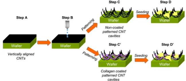
Our experimental design was summarized inFig. 2. First, the vertical-ly aligned CNT arrays were synthesized by the ACCVD method (Fig. 2, step A). Then deionized water was applied on these surfaces with a dropper to create cavities in the patterning step (Fig. 2, step B). CNT ar-rays were either treated with or without collagen (Fig. 2, step C′ and C; respectively) and MSCs from rat bone marrow were seeded (Fig. 2, step D and D′).
Presence of the asperities on the surface is critical for the preparation of a suitable scaffold for anchoring of the cells. Hence, we undertook the patterning step on the vertically aligned CNT arrays synthesized by ACCVD method in order to create a suitable so-called nest for the cells (Fig. 2, step A). To accomplish this task, we applied deionized water on the vertically aligned CNT arrays with a dropper and left for air dry-ing (Fig. 2, step B). Due to capillary forces exerted by water, the vertical-ly aligned CNT arrays patterned with the collapse of CNTs in equiaxed cavities/pockets, as shown inFig. 1d. Similarly, self-assembled pattern-ing of CNT arrays were also reported by another group[26]. The main mechanism of this formation is thought to be related to the hydropho-bic properties and elasto-capillary effect of aligned CNTs. The size of the CNT cavities on the surface was around 10μm wide (Fig. 1d). Fur-thermore, patterned CNT arrays were either treated with or without
collagen (step C′ and C inFig. 2, respectively).Fig. 1d, 1e and related in-sets show the non-coated cavities and collagen coated cavities in a com-parative manner. Finally, MSCs from rat bone marrow were seeded on the patterned non-coated and collagen coated CNT arrays (Fig. 2, step D and D′).
4.2. Characterization of MSCs
After the isolation from rat bone marrow, we characterized the MSCs both at mRNA and protein levels for P0, P1 and P2 groups (Fig. 3). Consistent with previous observations by us and others
[27,28], our results showed that MSCs were positive for the expres-sion of MSC markers (CD90, CD71 and CD29) but negative for hemato-poietic stem cell markers (CD45 and CD34) for all passages as expected at the transcript level (Fig. 3a). We further confirmed that these MSCs were positive for CD29 and negative for CD34 by Western blot analysis at the protein level (Fig. 3b).
4.3. Seeding MSCs on the patterned CNT arrays
A total of 3 × 10⁵ numbers of MSCs were seeded on the
non-coated and collagen non-coated patterned CNT surfaces. After 3 days, SEM analysis was performed (Fig. 4). Attached MSCs, which were from P0, were observed both in collagen coated (Fig. 4a) and non-coated (Fig. 4b) patterned CNT surfaces. In addition, numbers of at-tached MSCs on coated and non-coated patterned CNT surfaces were counted in the SEM images for three subsequent passages and average areal density was calculated dividing this number to the total surface area (Fig. 4c). Our plot revealed that the number of the MSCs decreased through the passage of the cells. The decrease was statistically signi fi-cant when the number of the cells was compared between P0 and P1 and P2 (Fig. 4c). Thus, these data suggest that very early passages of MSCs should be used for seeding purposes. The number of the cells both on coated and non-coated patterned CNTs continued to decrease at P2 compared to P1 but we did not observe a statistical significance between them. Interestingly, the number of the MSCs was significantly higher when they were cultured on non-coated compared to that of col-lagen coated CNT arrays at P0 but not at P1 and P2 (Fig. 4).
Recent literature on collagen/CNT composites prepared and ana-lyzed for use in scaffold applications reveals observations that beg further investigation. First of all, the goal for the development of such composite structures is not only to improve the poor mechanical properties of collagen, but also to add further functionality to the
scaffold[9,22]. For instance, Cho and Borgens prepared electrically conductive collagen/MWCNT composite structures and investigated the effect of CNT loading and applied electrical stimuli on the cell vi-ability of PC12[29]. Theirfindings indicated that the metabolic activ-ity of these cells decreased asymptotically by the CNT amount reaching a plateau at around 50% (wt.) CNT loading. However, there was no mention of a root cause for this observation. In contrast, our results shown inFigs. 4c and5clearly indicated that the number of MSCs for P0 was noticeably larger for the collagen coated patterned CNT surfaces compared to non-collagen coated ones. Concurrently, other studies also reported the improvement in the viability and the proliferation of different type of cells with the addition of CNT to the matrix which was ascribed to better attachment of the cells to the CNTs[30,31]. Hirata et al. showed that mouse osteoblast cells (MC3T3-E1) attached to a three-dimensional collagen sponge coated with MWCNTs exhibited higher DNA content than the uncoated colla-gen sponge[30]. In addition, MacDonald and co-workers showed an increase in the number of viable smooth muscle cells by increasing the mass ratio of CNT in collagen matrix[31]. One possible explana-tion for the MSCs preference of non-coated patterned CNT arrays could be related to the mechanical properties of ECM which was
known to have a significant impact on the attachment of stem cells
[32,33]. Collagen by itself has poor mechanical properties limiting its widespread usage in bioengineering [34]. On the other hand, MWCNT is one of the strongest materials known with a modulus of elasticity and tensile strength surpassing those of the strongest car-bonfibers[35].
As mentioned before, cell attachment to the ECM is also affected by surface topography[6,7,11]. We speculated that the collagen in fil-trated to the CNT array was acting as a smoothing agentfilling the gaps between the CNTs, thereby limiting the availability of the an-choring points for attachment of MSCs. When collagen was dropped on the patterned CNT surface, the gaps between the collapsed CNTs werefilled by collagen and we called this as ‘smoothing’. The SEM im-ages provided inFig. 1d and e, display the comparison of the as-is and collagen infiltrated CNT array surfaces where the gaps between CNTs were coated by collagen. Hence, regarding these images, roughness for as-is surfaces was different than collagen coated ones. Another important aspect of the study presented in this work is the use of dense (>109/cm2) vertically aligned CNT arrays. Such alignment of
the CNTs not only provided a homogenous surface minimizing local variations in the mechanical properties, but at the same time presented numerous anchoring points to the cells. Besides, in this study the vertically aligned CNT arrays werefirmly attached to the substrate beneath limiting the possible cytotoxic effects[20,21].
Toxicity of CNTs has been a controversial issue. There are reports claiming toxic effect of CNTs[17,18], whereas many reports with op-posite views exist[20,21]. It has been shown that proliferation and differentiation of rat bone marrow derived MSCs were inhibited by MWCNTs[36]. Therefore, it was critical to test whether our modified and patterned CNT arrays would have any deleterious effect on the cell viability or not (Figs. 4 and 5). In addition we have examined the effect of MWCNTs on different passages. For this purpose, we performed MTT assay to measure their viability on both non-coated and collagen coated patterned CNT arrays in different passages (Fig. 5). Our results showed that MSCs from early passages (P0) had not only the highest capacity of viability both on non-coated and col-lagen coated patterned CNT surfaces, but also had capacity higher than the control groups. Also, the increase of cell number for P0 on the non-coated patterned CNT surface (P0-CNT) compared to control was statistically significant. It is important to note that the reading of control group on MTT assay was obtained from cells on 96-well cul-ture plates without CNT arrays. Previously, it was shown that less than 40% cell viability at the MTT results suggested that the tested material is toxic[37]and should be further investigated with other methods. Our data inFig. 5 clearly showed that MSC viability is more than that of control at P0 and approximately 70% to that of con-trol group at P1 and 50% to that of concon-trol group at P2. Therefore, we can state that there is no cytotoxic effect of both coated and non-coated CNTs on the MSCs at P0 as well as in other passages. Thus, our data revealed that either non-coated or collagen coated pat-terned CNT arrays are providing a suitable environment for cells from early passages to survive and keep their differentiation potential. This should be remembered when scaffolds composed of CNTs are to be used for seeding cells. This may have important regenerative medi-cine applications. Our data also demonstrated the negative effect of CNTs on the number and metabolic activity of MSCs on later passages. MSCs in later passages (P1 and P2) indicating lesser counts (Fig. 4c) and viability (Fig. 5) on collagen coated or non-coated patterned CNTs than in early passage (P0) can be explained by the aging of MSCs[27,38,39]. Gruber et al. have shown that the mean percent se-nescence increased significantly with cell passaging[38] and high passage numbers adversely affected the functioning of stem cells[39]. While our results showed improved cell attachment and viability of MSCs on non-coated patterned CNT arrays, the need of a rigid sur-face such as Si for the growth of CNTs is a significant limiting factor for technological applications. The natural next step in such a study
Fig. 3. The expression of the markers for bone marrow derived MSCs and hematopoietic stem cells at (a) mRNA and (b) protein levels.
would be to embed CNTs while preserving their alignment in a biode-gradable matrix manufactured from chitosan, polylactic acid, etc.[40]. In this concern, our studies regarding the transfer of aligned CNT ar-rays to a polymer matrix are ongoing.
5. Conclusion
We investigated MSC viability on bare and collagen-coated pat-terned CNT arrays. First, our results revealed that MSCs attached to both non-coated and collagen coated patterned CNT arrays better than on bare 96-well culture plates for the early passage (P0). More-over, we did not encounter evidence for the toxicity of CNTs. Howev-er, cell numbers and viability decreased significantly on both coated and non-coated patterned CNT surfaces for later passages (P1 and P2). Furthermore, we found that collagen coating of CNTs had an im-pact on the adhesion of MSCs. This may suggest that MSC adhesion could be influenced by topography of the surface. Overall, this study demonstrated that patterned CNT arrays can serve as a permissive scaffold for MSC growth and adhesion. CNTs are not biodegradable and as such that they can be used as scaffolds where long-term sub-strates are needed for tissue engineering such as in regeneration after spinal cord or brain injury.
Acknowledgements
This work was supported partly by the Scientific and Technologi-cal Research Council of Turkey (TUBITAK) grants SBAG105S393 and
Fig. 4. SEM images after MSCs were seeded and cultured for 3 days on the (a) non-coated patterned CNT arrays and (b) collagen coated patterned CNT arrays. Insets show the magnified SEM images of the cells. (c) Average area density of MSCs on non-coated and collagen coated patterned CNT arrays at different passages. ANOVA was significant at p b 0.001. Multiple comparisons of control to other groups were performed using Fisher's test (Minitab 15 Statistical Software). * indicates significant p b 0.05.
Fig. 5. MTT assay graphs showing the percent viability of MSCs on the non-coated pat-terned CNT arrays (empty bars) and collagen coated patpat-terned CNT arrays (solid bars) at different passages. Dotted blue lines indicate the comparison of viability percentage on the non-coated CNT surfaces. Solid lines show the comparison of viability percentage on the collagen coated CNT surfaces. ANOVA was significant at p = 0.041 and p b 0.001 for non-coated and collagen coated CNT arrays, respectively. Multiple comparisons of con-trol to other groups were performed using Fisher's test (Minitab 15 Statistical Software). * indicates significant p b 0.05.
SBAG106S460 to K.C. Akcali, V. Bitirim and G. Kucukayan-Dogu thank TUBITAK forfinancial support. The authors are grateful to Rasit Turan and Mustafa Kulakci for electron beam evaporation facility at Middle East Technical University (Turkey).
References
[1] Z. Tokcaer-Keskin, A.R. Akar, F. Ayaloglu-Butun, E. Terzioglu-Kara, S. Durdu, U. Ozyurda, M. Ugur, K.C. Akcali, Can. J. Physiol. Pharmacol. 87 (2009) 143–150. [2] A.J. Nauta, W.E. Fibbe, Blood 15 (2007) 3499–3506.
[3] P.X. Ma, Adv. Drug Deliv. Rev. 60 (2008) 184–198.
[4] W. Li, R. Tuli, X. Huang, P. Laquerriere, R.S. Tuan, Biomaterials 26 (2005) 5158–5166. [5] J.L. Ifkovits, J.J. Devlin, G. Eng, T.P. Martens, G. Vunjak-Novakovic, J.A. Burdick,
Appl. Mater. Interfaces 1 (2009) 1878–1886.
[6] M.J. Dalby, N. Gadegaard, R. Tare, A. Andar, M.O. Riehle, P. Herzyk, C.D.W. Wilkinson, R.O.C. Oreffo, Nat. Mater. 6 (2007) 997–1003.
[7] D.R. Jung, R. Kapur, T. Adams, K.A. Giuliano, M. Mrksich, H.G. Craighead, D.L. Taylor, Crit. Rev. Biotechnol. 21 (2001) 111–154.
[8] F. Gelain, S. Panseri, S. Antonini, C. Cunha, M. Donega, J. Lowery, F. Taraballi, G. Cerri, M. Montagna, F. Baldissera, A. Vescovi, ACS Nano 5 (2011) 227–236. [9] T.D.B. Nguyen-Vu, H. Chen, A.M. Cassell, R.J. Andrews, M. Meyyappan, J. Li, IEEE
Trans. Biomed. Eng. 54 (2007) 1121–1128.
[10] M.J. Dalby, S.J. Yarwood, M.O. Riehle, H.J. Johnstone, S. Affrossman, A.S. Curtis, Exp. Cell Res. 276 (2002) 1–9.
[11] T.P. Kunzler, C. Huwiler, T. Drobek, J. Voros, N.D. Spencer, Biomaterials 28 (2007) 5000–5006.
[12] F. Gentile, L. Tirinato, E. Battista, F. Causa, C. Liberale, E.M. di Fabrizio, P. Decuzzi, Biomaterials 31 (2010) 7205–7212.
[13] E. Hirata, M. Uo, H. Takita, T. Akasaka, F. Watari, A. Yokoyama, Carbon 49 (2011) 3284–3291.
[14] R.J. Chen, S. Bangsaruntip, K.A. Drouvalakis, N.W.S. Kam, M. Shim, Y. Li, W. Kim, P.J. Utz, H.J. Dai, PNAS 100 (2003) 4984–4989.
[15] C.A. Poland, R. Duffin, I. Kinloch, A. Maynard, W.A. Wallace, A. Seaton, V. Stone, S. Brown, W. MacNee, K. Donaldson, Nat. Nanotechnol. 3 (2008) 423–428. [16] K. Soto, K.M. Garza, L.E. Murr, Acta Biomater. 3 (2007) 351–358.
[17] G. Jia, H. Wang, L. Yan, X. Wang, R. Pei, T. Yan, Y.L. Zhao, X.B. Guo, Environ. Sci. Technol. 39 (2005) 1378–1383.
[18] S.K. Smart, A.I. Cassady, G.Q. Lu, D.J. Martin, Carbon 44 (2006) 1034–1047. [19] L. Zhu, D.W. Chang, L. Dai, Y. Hong, Nano Lett. 7 (2007) 3592–3597.
[20] A.O. Lobo, M.A.F. Corat, E.F. Antunes, M.B.S. Palma, C. Pacheco-Soares, E.E. Garcia, E.J. Corat, Carbon 48 (2010) 245–254.
[21] S. Giannona, I. Firkowska, J. Rojas-Chapana, M. Giersig, J. Nanosci. Nanotechnol. 7 (2007) 1679–1683.
[22] P.R. Supronowicz, P.M. Ajayan, K.R. Ullmann, B.P. Arulanandam, D.W. Metzger, R. Bizios, J. Biomed. Mater. Res. 59 (2002) 499–506.
[23] X. Zhang, S. Prasad, S. Niyogi, A. Morgan, M. Ozkan, C.S. Ozkan, Sensors Actuators B 106 (2005) 843–850.
[24] E. Money, P. Dockery, U. Greiser, M. Murphy, V. Baron, Nano Lett. 8 (2008) 2137–2143.
[25] M.M. Bradford, Anal. Biochem. 72 (1976) 248–254.
[26] C.T. Wirth, S. Hofmann, J. Robertson, Diam. Relat. Mater. 17 (2008) 1518–1524. [27] Z. Tokcaer-Keskin, Z.G. Dikmen, F. Ayaloglu-Butun, S. Gultekin, S.M. Gryaznov,
K.C. Akcali, Stem Cell Rev. 6 (2010) 224–233.
[28] A.A. Mangi, N. Noiseux, D. Kong, H. He, M. Rezvani, J.S. Ingwall, V.J. Dzau, Nat. Med. 9 (2003) 1195–1201.
[29] Y. Cho, R.B. Borgens, J. Biomed. Mater. Res. A 95A (2010) 510–517.
[30] E. Hirata, M. Uo, H. Takita, T. Akasaka, F. Watari, A. Yokoyama, J. Biomed. Mater. Res. B 90B (2009) 629–634.
[31] R.A. MacDonald, B.F. Laurenzi, G. Viswanathan, P.M. Ajayan, J.P. Stegemann, J. Biomed. Mater. Res. A 74 A (2005) 489–496.
[32] I. Sridharan, T. Kim, R. Wang, Biochem. Biophys. Res. Commun. 381 (2009) 508–512. [33] A.J. Engler, S. Sen, H.L. Sweeney, D.E. Discher, Cell 126 (2006) 677–689. [34] E.E. Da Silva, H.H.M.D. Colleta, A.S. Ferlauto, R.L. Moreira, R.R. Resende, S. Oliveira,
G.T. Kitten, R.G. Lacerda, L.O. Ladeira, Nano Res. 2 (2009) 462–473. [35] C. Li, T.-W. Chou, Compos. Sci. Technol. 63 (2003) 1517–1524. [36] D. Liu, C. Yi, D. Zhang, J. Zhang, M. Yang, ACS Nano 4 (2010) 2185–2195. [37] B.R. Twaites, C.H. Alarcon, M. Lavigne, A. Saulnier, S. Pennadam, D. Cunliffe, D.C.
Gorecki, C.J. Alexander, J. Control. Release 108 (2005) 472–483.
[38] H. Gruber, S. Somayaji, F. Riley, G. Hoelscher, H. Norton, J. Ingram, E.N. Hanley, Biotech. Histochem. 87 (2012) 303–311.
[39] P.R. Crisostomo, M. Wang, G.M. Wairiuko, E.D. Morrell, A.M. Terrell, P. Seshadri, U.H. Nam, D.R. Meldrum, Shock 26 (2006) 575–580.
[40] G. Bayramoglu, K.C. Akcali, S. Gultekin, E. Bengu, M.Y. Arica, Macromol. Res. 19 (2011) 385–395.