Pamukkale Univ Muh Bilim Derg, 24(4), 605-609, 2018
Pamukkale Üniversitesi Mühendislik Bilimleri Dergisi
Pamukkale University Journal of Engineering Sciences
605
A comparative survey on recovery performance of thermo-electric
generator recovery system with air cooling during warming process of
internal combustion gasoline engines
İçten yanmalı benzinli motorların ısınma sürecinde hava soğutmalı bir
termoelektrik jeneratör geri kazanım sisteminin geri kazanım performansı
üzerine karşılaştırmalı bir inceleme
Mehmet Akif KUNT1*
1Department of Motor Vehicles and Transportation Technologies, Tavsanlı Vocational School, Dumlupinar Univ., Kutahya
Received/Geliş Tarihi: 25.12.2017, Accepted/Kabul Tarihi: 12.04.2018
* Corresponding author/Yazışılan Yazar Research Article/Araştırma Makalesi doi: 10.5505/pajes.2018.66503
Abstract Öz
Thermoelectric generators are long-life electricity generators that operate according to the Seebeck thermoelectric effect and produce DC voltage by utilizing the temperature difference on hot and cold surfaces, without moving parts. The ability to generate electricity directly in any situation where the temperature difference between the surfaces of the thermoelectric modules arises makes it possible to generate electricity from the first time in the exhaust systems of the internal combustion engines. It is very important to examine the recovery of the thermoelectric generators in the heating process in the internal combustion engines due to the reduced generator efficiency at low revs. In this study, thermoelectric generators were used to provide exhaust heat recovery in heating process of an internal combustion gasoline engine, electrical gains obtained at three different temperature averages were investigated and experimental and simulated results were compared. A maximum ΔT = 165 °C temperature difference was obtained between the module surfaces. In the experiments performed, ΔT = 165 °C, RL = 10 Ω load resistance, maximum 6.75 V voltage, 0.65 A current is obtained. Experimental and simulation results are generally in coherence.
Termoelektrik jeneratörler, Seebeck termoelektrik etkisine göre çalışan, sıcak ve soğuk yüzeylerde sıcaklık farkından yararlanarak DC gerilim üreten, hareketli parçaları olmayan uzun ömürlü elektrik üreteçleridir. Termoelektrik modüllerin yüzeyleri arasında sıcaklık farkının meydana geldiği her durumda doğrudan elektrik üretebilmesi içten yanmalı motorların egzoz sistemlerinde ilk çalışmadan itibaren elektrik üretimini mümkün kılmaktadır. Düşük devirlerde alternatör veriminin azalması sebebiyle termoelektrik jeneratörlerin içten yanmalı motorlarda ısınma sürecinde geri kazanımının incelenmesi oldukça önemlidir. Bu çalışmada termoelektrik jeneratörler kullanılarak içten yanmalı benzinli bir motorun ısınma sürecinde egzoz atık ısı geri kazanımı sağlanmış, oluşan 3 farklı sıcaklık farkında elde edilen elektriksel kazanımlar incelenmiş, deneysel ve benzetim sonuçları karşılaştırılmıştır. Modül yüzeyleri arasında maksimum ∆T=165 °C sıcaklık farkı elde edilmiştir. Yapılan deneylerde ΔT=165 °C, RL=10 Ω yük direncinde maksimum 6.75 V gerilim, 0.65 A akım elde edilmiştir. Deneysel ve benzetim sonuçları genel olarak uyumludur.
Keywords: Waste heat, Warming process, Recovery system,
Exhaust system Anahtar kelimeler: Atık ısı, Isınma süreci, Geri kazanım sistemi, Egzoz sistem
1 Introduction
Thermo-electric generators are recovery structures designed thermally in parallel form with the help of ceramic sheets in order to provide serial and thermal expansion electrically by the help of p- and n-type semi-conductive. Thermo-electric energy is mainly used when recovery of heat cannot be made especially in waste form [1]. The ability to generate electricity directly in any situation where the temperature difference between the surfaces of the thermoelectric modules arises makes it possible to generate electricity from the first time in the exhaust systems of the internal combustion engines. Operation of internal combustion engines at low engine revs decreases the efficiency of alternators. On the other hand, thermo-electric generator (TEG) modules can generate electricity independently from the rev and for a longer period of time due to exhaust temperature does not decrease rapidly. Therefore, recovery performance of TEGs in internal combustion engines at low temperature should be examined. Waste heat generated by automobiles from exhaust is an
important heat source resulting in high power production in which TEGs can be used [2].
Thacher et al. [3] in their experiment carried out by placing a proto-type thermo-electric generator module in the exhaust of a 1999 model GMC Sierra brand vehicle with an V8 engine of 5.3 liter, have determined that such vehicle provided a fuel saving between 4% and 5.3%.
Bass et al. [4] in their article, have stated that they obtained approximately 1 kW power by means of 72 pcs. HZ-14 thermo-electric modules (9 serial, 8 parallel arms) installed in the exhaust of a diesel truck engine with 550 HP. It has been determined that output power of thermo-electric module does not depend mostly upon load of engine rather than rev speed of engine.
Kobayashi et al. [5] used 72 pcs. SiGe TEG on a 3000 cc gasoline engine. TEGs were placed on a rectangular exhaust pipe. In order to cool the cold part of TEGs, cooling water of the vehicle was used. Such system obtained 1.2 W electric power, 0.7 V voltage and 0.9% energy recovery for each TEG at vehicle speed
Pamukkale Univ Muh Bilim Derg, 24(4), 605-609, 2018 M. A. Kunt
606 of 60 km/h, exhaust temperature of 1141°C and temperature
difference of 563 °C.
Kunt and Güneş [6] have studies on exhaust waste heat recovery in our country. Such researchers have designed a thermo-electric generator system with air cooling to be used recovery of waste heat in exhaust systems of internal combustion engines, and made performance tests different load resistances. Theoretical and experimental results have been compared. From such systems, maximum 16.2 V voltage and 0.27 A current were obtained at 𝑇𝑐= 313 𝐾, ∆𝑇 = 210 𝐾, 𝑅𝐿=
125 Ω load resistance.
Temizer et al. [7] have developed a waste heat recovery proto-type with thermo-electric generator on an aluminium alloy orthogonal body and applied it on exhaust system of a diesel internal combustion engine. In such proto-type, 40 pcs. TEG modules were used, and cooling of cold part was carried out by engine cooling water. Performance of the thermo-electric generator system has been examined according to changing rev and load state. Such system provided 156.7 W electrical power under 100 Nm engine power and at 3500 rpm engine rev. Alexander et al. [8] have made a study on waste heat systems with thermo-electric generators in motorcycle engines. They obtained an electrical power of 0.4694 W at ∆T=48.73 °C temperature difference by using Melcor HT3-12-30 TEG module. Moreover, they formed a mathematical model using statements of thermo-electric effect and average Seebeck coefficient. Average relative error of such model is 1.75%. In another study, using TEP1-1264-1.5 model TEG at 200C,3V voltage, 0.637A current and 1.91 W power was obtained while the model of TEG was replaced with TMG-450-0.8-1.0 in the same conditions, this time 8.97 V voltage0.41A current and 3.742W power was obtained [9].
In this study, exhaust waste heat recovery has been made during heating process of an internal combustion gasoline engine using thermo-electric generators; electrical gains obtained from 3 different temperature differences have been examined; and experimental and simulation results have been compared. Furthermore, battery charging potential of the vehicle has been investigated according to voltage and current values. The experiments have been carried out without load at rev number (1000 rpm) during heating process of the engine. The performance of the waste heat recovery system will be presented in another research paper at engine speeds where the test motor is used more frequently.
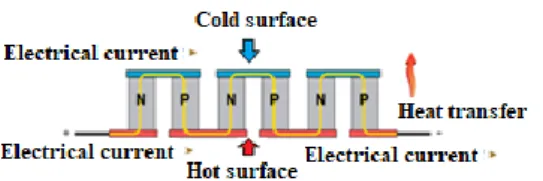
Thermoelectric generators are long-life electricity generators that operate according to the Seebeck thermoelectric effect and produce DC voltage by utilizing the temperature difference on hot and cold surfaces, without moving parts.Thermoelectric generators use semi-conductive materials, and reactions shown by n and p type semi-conductive during heat transfer vary. In n type semi-conductive, the heat is transferred by means of free electrons, while in p type semi-conductive, they are transferred by gaps. By connecting n and p type semi conductive by a conductive material, a single cell is formed. By combining such cells, thermo-electric module is formed [10]. General structure of TEG modules is shown in Figure 1.
Figure 1: General structure of TEG modules.
In thermo-electric generators, hot zone heat (𝑄ℎ), cold zone
heat (𝑄𝑐), electrical power (𝑃𝑒) and open-circuit voltage (𝑉𝑂𝐶𝑉)
are stated by following relations [11]. Qh= 2αITh+ 2kA ℓ ∆T − 1 2I2 2ρℓ A (1) 𝑄𝑐= 2𝛼𝐼𝑇𝑐+ 2𝑘𝐴 ℓ ∆𝑇 + 1 2𝐼2 2𝜌ℓ 𝐴 (2) 𝑃𝑒= 𝑄ℎ− 𝑄𝑐= 2𝛼𝐼∆𝑇 − 𝐼22𝜌ℓ𝐴 (3) 𝑉𝑜𝑐𝑣= 𝛼∆𝑇 (4)
Here, α, ρ, k, A and l refer respectively to Seebeck coefficient, electrical resistance, thermal conductivity, cross-sectional area and pellet length. The obtained current value is stated as follows on the basis of Ohm law.
𝐼 = 𝑉𝑜𝑐𝑣 𝑅𝐼+ 𝑅𝐿=
𝛼𝐴∆𝑇
𝜌ℓ(1 + 𝑚) (5) “m” symbol shown in equation no (5) is the ratio of load resistance (RL) to electrical internal resistance (RI). When
equation no (5) is written in equation no (3), following relation in terms of electrical power.
𝑃𝑒=2𝑁𝑚𝛼 2∆𝑇2𝐴
𝜌ℓ(1 + 𝑚)2 (6)
In order to obtain maximum electrical power, m=1 equation should be provided. The loaded voltage obtained,
𝑉 =𝑃𝑒 𝐼 = 2𝑁 (
𝑚
1 + 𝑚) 𝛼∆𝑇 (7) The relation between pellet and ceramic surfaces, selection of connection materials, state of electrical connections, thermal contact thickness significantly change performance of TEG modules. Accordingly, when equations no (5) and (6) are arranged considering the contact state, current and electrical power are obtained as follows [12]-[13]
𝐼 = 𝛼𝐴∆𝑇
𝜌ℓ𝑚(1 + 𝑚) (8)
𝑃𝑒=2𝑁𝑚𝛼 2∆𝑇2𝐴
𝜌ℓ𝑚(1 + 𝑚)2 (9)
2 Material and methods
Main body of exhaust gas recovery system was produced from CRS (Cold rolled sheet) sheet profile. TEGs were placed on CRS sheet profile and aluminium coolers were used in order to cool cold parts. TEGs and aluminium cooling fins were connected by tightening clamps [Figure 2].
Pamukkale Univ Muh Bilim Derg, 24(4), 605-609, 2018 M. A. Kunt
607 Figure 2: General view of recovery system.
In the system 8 pcs TG 12-8 thermo-electric modules were used. Technical specification of TG12-8 TEG modules used in experiments are shown in Table 1.
Table 1: Technical specification of thermo-electric generator [14].
TEG
TEG module TG-12-8-01L Width x lenght x height (mm) 44 x 40 x 3.6
Hot zone temperature (°C) 230 Cold zone temperature (°C) 50
Thermal resistance (°C/W) 1.13 Load resistance in optimum
conditions (η) 3.46 Optimum efficiency (%) 4.97
Heat of exhaust fluid passing through the body is cooled by an electrical fan while being transferred on thermo-electric generators. In chassis dynamometers, SUN ROAD-A-MATIC XI cooling fan was used. Electrical voltage is formed at the rate of temperature difference from edges of modules connected to each other in series. In order to increase heat conductivity of TEG module on hot and cold surfaces, thermal conductor paste was applied. The experiment engine is 2002 model 1242 cc 70HP Fiat Albea engine. Technical specification of experiment model is shown in Table 2.
Table 2: Technical specification of experiment engine. Brand Fiat Albea Engine size 1242 cc Valve structure OHC Number of Cylinders 4 Compression ratio 10.6 Number of Valve per Cylinder 4 Fuel Type Gasoline
In order to record open circuit voltage, loaded voltage, current, power values, and to equal external load resistance to internal resistance of module, CHROMA brand electronic load was used. In order to measure temperatures of hot and cold parts, ELİMKO E-TC15-1K1PT type thermocouple thermometer was used. The thermometers were placed in the canals between modules and aluminium cooler on the cold part and at inlet and outlet of exhaust recovery system. Measured temperature values were processed in ELIMKO E680 scanner device and transferred into the computer. The measurements were carried out after fixed temperature conditions were maintained in all measurement points. General view of experiment mechanism is shown in Figure 3.
Figure 3: General view of experiment mechanism.
3 Evaluation of test results
In Figure 4, Th, Tc,, TH and ∆T change depending on time at
unloaded engine speed of 1000 rpm is seen. At unloaded engine rev of 1000 rpm, the experiment was carried out up to maximum module temperature of TH. A temperature difference
of ∆T=165 °C was obtained between module surfaces at TH =250 °C exhaust temperature. All temperatures increased
rapidly at the beginning of the experiment (<200 s), and such increase tended to decrease in following time interval.
Figure 4: Change of temperatures depending on time (1000 rpm).
In Figure 5, Th, Tc, and ∆T change is seen depending on exhaust
internal temperature at unloaded engine speed on 1000 rpm. With the increase of TH temperature, increase speed of
Tc temperature stayed slowed than the increase speed of
Th temperature.
Figure 5: Change of system temperatures depending on internal temperature change (1000 rpm).
As CRS profile was used in main body of TEG recovery system, Th temperature changes at closer values of exhaust internal
temperature. For temperatures TH= 50 °C, 100 °C, 150 °C,
200 °C, 250 °C, temperature differences of ∆T= 25 °C, 67 °C, 105 °C, 135 °C, 165 °C were measured respectively.
In Figure 6, the change of voltage, depending on change of load resistance at 3 different temperature difference obtained at unloaded engine rev of 1000 rpm, is seen. For a fixed load resistance, as temperature difference decreases, the electrical potential difference decreases too with Seebeck effect.
Pamukkale Univ Muh Bilim Derg, 24(4), 605-609, 2018 M. A. Kunt
608 Figure 6: System voltage change depending on load resistance
change (1000 rpm).
As the temperature difference increases, the voltage increases too and the voltage obtained can be arranged according to change of load resistance. For operation temperatures in which temperature difference is high and the voltage is more, the voltage values get saturated later at higher values of load resistance. The highest voltage was obtained as 9.93 V at temperature difference of ΔT=165 °C, RL=40 Ω. At temperature
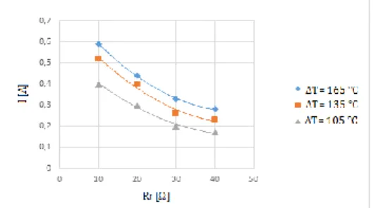
differences of ΔT=105 °C, ΔT=135 °C and ΔT=165 °C, respectively V= 7.6 V, V= 9.09 V and V= 9.93 V were obtained. In Figure 7, change of current, depending on load resistance change at 3 difference temperature difference obtained at unloaded engine rev of 1000 rpm, is seen. For fixed load resistance, as the temperature difference decreases, obtained current decreases too. Moreover, at fixed temperature difference, as the load resistance decreases, current value increases. The reason of such trend is the decrease in internal circuit resistance. As internal resistance decreases, obtained current value increases. With decrease of load resistance, load resistance and internal resistance values tend to be equally and accordingly current value increases. The highest current RL=10 Ω was obtained as 0.65 A at temperature difference of
ΔT=165 °C. At temperature differences of ΔT=105 °C, ΔT=135 °C and ΔT=165 °C, respectively I= 0.4 A, I= 0.58 A and I= 0.65 A were obtained.
Figure 7: System current change depending on load resistance change (1000 rpm).
In Figure 8, experimental and theoretical simulation of load change, depending on load resistance change at maximum temperature (ΔT=165 °C), is seen. As the load resistance increases, the obtained current value decreases. According to experiment and simulation results, the smallest average relative error was obtained as 4.54% at load resistance of RL=20 Ω. According to the graphics, simulation model has been
considered as accurate. According to experimental results, at load resistance of RL=10 Ω, due to the difference between
obtained and accepted Seebeck coefficient of modules, rate of error was at the highest amount. With the increase of load resistance, the Seebeck coefficient obtained in experimental results increases and simulation and experiment results become closer to each other.
Figure 8: Comparative system current change graphic depending on load resistance change (ΔT=165 °C, 1000 rpm). In Figure 9, experimental and theoretical simulation of load change, depending on load resistance change at maximum temperature, is seen. The power takes maximum value for small load resistance values, and tends to decrease with increase of load resistance. For an active circuit, the resistance value to be connected to the system can take maximum power when it is equal to internal resistance of circuit. Maximum power value is reached when internal resistance is equal to load resistance, and internal resistance of TEG takes small values such as a few ohm, accordingly, the load resistance in which maximum power is observed is small too.
Figure 9: Comparative system power change graphic depending on load resistance change (ΔT=165 °C, 1000 rpm). In Figure 10, voltage change, depending on current change at 3 different temperature differences, is seen. For fixed current value, as the temperature difference increases, voltage value increases too. With the increase of current value, the voltage obtained in all temperature differences decreases. Voltage-current equation according to experimental results is shown in Table 3. The equation has been formed linear as 𝑉 = 𝑎 𝐼 + 𝑏.
Figure 10: Voltage change depending on current change. Table 3: Equation table for voltage-current change.
Temperature Equation
Th=237 °C ΔT=165 °C T̅ = 154.5 °C V=-8.1063I+11.87
Th=193 °C ΔT=135 °C T̅ = 125.5 °C V=-10.004I+11.114
Th=145 °C ΔT=105 °C T̅ = 92.5 °C V=-13.2I+9.5209
The charging process is carried out by a charge system composed of alternator and regulator. Such process is carried out by fixed voltage as a filling action. Charging voltage value is between 13.8 volt and 14.2 volt. Charging current is selected from 1/10-1/20 of battery capacity. In experiments, at ΔT=165 °C and RL=10 Ω load resistance, maximum 6.75 V
Pamukkale Univ Muh Bilim Derg, 24(4), 605-609, 2018 M. A. Kunt
609 voltage and 0.65 A current were obtained. Accordingly, number
of modules required for charging a battery of 12V 40Ah and related cost details are given in Table 4.
Table 4: Number and cost of modules required for charging vehicle battery
Module Number of
Module Price ($) Unit cost ($) Total Obtained battery charge TEG 12-8 102 31 3162 16.59V, 3.9A
4 Results and discussion
In this article, and air cooling heat recovery system, to be used in exhaust of internal combustion engines, has been designed. Cold part of such system has been planned to be fed by ambient air. The experiments were carried out at engine speed (1000 rpm) of warming of process of the engine. Maximum ∆T=165 °C temperature difference was obtained between module surfaces. At fixed load resistance, as the temperature difference increases, the obtained voltage increases. The highest voltage was obtained as 9.93 V at RL=40 Ω and ΔT=165 °C temperature difference. At temperature differences of ΔT=105 °C, ΔT=135 °C and ΔT=165 °C, respectively V= 7.6 V, V= 9.09 V and V= 9.93 V were obtained.
Experiment and simulation results are generally in compliance. The smallest relative error has been obtained as 4.54% at load resistance of RL=20 Ω according to experiment and simulation results. The power takes maximum value for small load resistance values and tends to decrease with the increase of load resistance.
In the experiments, at ΔT=165 °C and RL=10 Ω load resistance, maximum 6.75 V voltage and 0.65 A current have been obtained. Accordingly, in order to charge a battery of 12V 40Ah, 17 pcs of TEG 12-8 module should be connected in series in 6 arms. In this manner, 16.59 V charge voltage and 3.9 A charge current are obtained.
When the results obtained from this study were compared with the similar studies [9] it is seen that higher recovery values were obtained. Using Seebeck coefficient in the mathematical model leads to a lower relative error. It was concluded after comparative analysis of mathematical models such as Alexander and others [8].
The experiments were carried out unloaded at engine speed of 1000 rpm. In case of increase in rev number or engine load, filling amount taken into cylinders will increase and exhaust temperatures will rise. The increase in exhaust temperature will increase recovery energy, too. When recovery energy increases, the number of modules required to charge the battery will decrease.
5 References
[1] Kunt MA. “İçten yanmalı motor atık ısılarının geri kazanımında termoelektrik jeneratörlerin kullanımı”. El-Cezerî Fen ve Mühendislik Dergisi, 3(2), 192-203, 2016.
[2] Weng CC, Huang MJ. “A simulation study of automotive waste heat recovery using thermoelectric power generator”. International Journal of Thermal Sciences, 71, 302-309, 2013.
[3] Thacher EF, Helenbrook BT, Kari MA, Richter CJ. “Testing of an automobile exhaust thermoelectric generator in a light truck”. Procedings of the Instituion of Mechanical Engineers, Part D: Journal of Automobile Engineering, 221, 95-107, 2006.
[4] Bass JC, Kushch AS, Elsner NB. “Thermoelectric Generator (TEG) for Heavy Diesel Trucks”. http://www.hi-z.com/tp2001.php (12.04.2010).
[5] Kobayashi M, Ikoma K, Furuya K, Shinohara K, Takao H, Miyoshi M, Imanishi Y, Watabane T. “Thermoelectric generation and related properties of conventional type module based on Si-Ge alloys”. 15th International
Conference on Thermoelectrics, Pasadena, USA, 26-29 March 1996.
[6] Kunt MA, Güneş H. “Termoelektrik jeneratörlerin içten yanmalı motorların egzoz sistemlerinde farklı yük dirençlerinde uygulaması”. 13. Uluslararası Yanma Sempozyumu, Bursa, Türkiye 9-11 Eylül 2015.
[7] Temizer İ, İlkılıç C. “İçten yanmalı dizel motorunun atık egzoz gazı enerjisi kullanılarak elektrik enerjisi üretimi”. Pamukkale Üniversitesi Mühendislik Bilim Dergisi, 23(4), 330-336, 2017.
[8] Alexander DS, Steven RA, Daniel JI. “Motorcycle waste heat energy harvesting”. Industrial and Commercial Applications of Smart Structures Technologies, San Diego, United States, 30 April 2008.
[9] Kaya AY. Experimental Research of Thermoelectric System that Worked by the Heat on Exhaust Gas. MSc Thesis, Süleyman Demirel University, Isparta, Turkey, 2010.
[10] Özgün H. Termoelektrik Jeneratörlerin Çok Düşük Sıcaklıklarda Teori ve Deneysel Karakterizasyonu. Yüksek Lisans Tezi, İstanbul Teknik Üniversitesi, İstanbul Türkiye, 2009.
[11] Hun SH, Yun HK; Seo YK, Sukkee U; Jae MH., “Performance measurement and analysis of a thermoelectric power generator”. Thermal and thermomechanical phenomena in electronic systems (ITherm) 12th IEEE Intersociety
Conference , Las Vegas, USA, 2-5 June 2010.
[12] Rowe DM. CRC Handbook of Thermoelectrics, Wales. UK, CRC Press, 1995.
[13] Rowe DM. Thermoelectric Handbook Macro to Nano, Wales UK. Taylor & Francis Group Press, 2007.
[14] Heremans J. “Materials May Help Autos Turn Heat Into Electricity”.
www.sciencedaily.com/releases/2008/07/0807241503 40.htm (17.11.2017).