FORM AND PART THROUGH STANDARD / NON‐STANDARD DUALITY
Graduate School of Economics and Social Sciences
of
İhsan Doğramacı Bilkent University
by
GÖKHAN KINAYOĞLU
In Partial Fulfilment of the Requirements for the Degree of
DOCTOR OF PHILOSOPHY
in
DEPARTMENT OF
INTERIOR ARCHITECTURE AND ENVIRONMENTAL DESIGN
İHSAN DOĞRAMACI BILKENT UNIVERSITY
ANKARA
September 2017
ABSTRACT
FORM AND PART THROUGH STANDARD / NON‐STANDARD
DUALITY
Kınayoğlu, Gökhan Ph.D. in Interior Architecture and Environmental Design Supervisor: Assoc. Prof. Dr. Burcu Şenyapılı Özcan September 2017This thesis formulates its research through a two‐fold approach: it introduces a novel algorithm, but first it establishes the relationship model through which the assessment of the algorithm should be made. It discusses the intrinsic relation of “form” and “part” in architecture, through the analysis of concepts “standard” and “non‐standard.” The form is the overall shape of an object and part is the numerous constituents of form. “Standard” ‐which is a central trait for architecture‐ and “non‐ standard” ‐a later introduction to architecture‐ consisting of various formal alternatives, are included for their important formal and constructional characteristics. All four concepts are studied in their historical contexts and in relation to secondary themes, like tectonics, mass‐production, and mass‐ customization. Simple essential techniques and various geometric formations in architecture are also covered through built examples to further demonstrate the aspects of “standard” and “non‐standard,” in terms of “form” and “part.” Based on these four concepts, a quadripartite relation is established. The relationship model formulates a significant interpretation and interrelation of the four concepts, hence creates an analytical framework. Through the findings of the quadripartite relation’s last partition, an algorithm is devised. The algorithm can generate various alternative infrastructure models for surfaces of revolution through several
parameters. The findings demonstrate essential advantages in terms of standardization, material use, simplicity and ease of assembly. The algorithm can be altered slightly to adapt to other three partitions. Keywords: Algorithm, Computer‐aided design, Non‐standard, Standard, Technique.
ÖZET
STANDART / STANDART‐OLMAYAN İKİLEMİ ÜZERİNDEN BÜTÜN
VE PARÇA
Kınayoğlu, Gökhan Doktora, İç Mimarlık ve Çevre Tasarımı Bölümü Tez Danışmanı: Doç. Dr. Burcu Şenyapılı Özcan Eylül 2017 Bu tez araştırmasını iki yönlü bir yaklaşım ile şekillendirmektedir: yeni bir algoritma önermektedir, fakat önce algoritmanın değerlendirilebilmesi için gereken ilişkisel modelini kurmaktadır. Çalışma, “biçim” ve “parça”nın mimarlıktaki içsel ilişkisini, “standart” ve “standart‐olmayan” kavramları üzerinden tartışmaktadır. Biçim bir objenin bütün şeklidir ve parça, biçimin sayısız bileşenleridir. Mimarlık için merkezi bir özellik olan “standart,” ve mimarlığa daha sonradan dahil olmuş, birçok biçimsel alternatiflerden oluşan “standart‐olmayan” kavramları sahip oldukları biçimsel ve yapısal niteliklerinden dolayı çalışmaya dahil edilmişlerdir. Dört kavramın hepsi tarihsel bağlamları ve tektonik, seri‐üretim, seri‐özelleştirme gibi ikincil temalar ile ilişkilendirilerek incelenmiştir. "Standart" ve "standart dışı" kavramlarını "biçim" ve "parça" açısından daha fazla açıklamak için, mimarideki basit ana teknikler ve çeşitli geometrik oluşumlar da, yapılı örnekler aracılığıyla ele alınmıştır. Bunları temel alarak, dört parçalı bir bağıntı kurulmuştur. Bu bağıntı, dört kavramın önemli bir yorumlamasını ve kavramların birbirleriyle ilişkisini formüle etmekte ve bu sayede analitik bir çerçevesini oluşturmaktadır. Dört parçalı bağıntının son bölümünün bulguları üzerinden bir algoritma tasarlanmıştır. Algoritma, çeşitli parametreleri kullanarak dönel yüzeyler için birçok alternatif enfrastrüktür modelioluşturabilmektedir. Bulgular, standardizasyon, malzeme kullanımı, basitlik ve kurulum kolaylığı açısından önemli avantajlar sunmaktadır. Algoritma, az miktarlarda farklılaştırılarak diğer üç bölüme de benzer şekilde uyarlanabilir. Anahtar Kelimeler: Algoritma, Bilgisayar‐destekli tasarım, Standart, Standart‐ olmayan, Teknik.
ACKNOWLEDGEMENTS
First and foremost, I would like to thank my supervisor Assoc. Prof. Burcu Şenyapılı Özcan for her contributions throughout. I also would like to acknowledge Prof. Varol Akman, Assist. Prof. Yasemin Afacan and my unofficial committee member Aysu Berk for their critics and contributions. The process would not be this much clear without your influences. Although involved at the last stage, I would like to share my deepest gratitude and gratifications with Assist. Prof. Başak Uçar and Assist. Prof. Derin Inan, for their insightful comments. I would like to thank Google for its incredible possibilities and developments in tools for research, when compared to 1990’s and even first decade of 2000’s. This thesis would be a limited pile without the possibilities it offered. Another crucial figure for the conclusion of the process that I wish to thank, whom is not even aware of what he has delivered at the last minute, is Prof. Michael J. Ostwald. Thank you, sir, you made my life. I would also like to thank TÜBİTAK – BİDEB for supporting my PhD studies with a financial scholarship. And last, but not least, on contrary the most; to you Günce, my dearest. Always…
TABLE OF CONTENTS
ABSTRACT ... iii ÖZET ... v ACKNOWLEDGEMENTS ……….... vii TABLE OF CONTENTS ... viii LIST OF FIGURES ... x CHAPTER 1: INTRODUCTION ... 1 1.1. Research Objectives and Scope of Study ... 3 1.2. Structure of Thesis ... 5 CHAPTER 2: FORM AND PART ... 8 2.1. The Concept of Form ... 11 2.2. Generation of Part ... 13 2.3. Tectonic Dependence of Form and Part ... 17 2.4. Topology as a Tool for Inspecting the Formal Aspects of Parts ... 19 2.5. Geometric Formations in Architecture ... 22 2.5.1. Simple Geometric Elements ... 23 2.5.2. Surfaces of Revolution ... 25 2.5.3. Ruled Surfaces ... 32 2.5.4. Freeform Surfaces ... 38 CHAPTER 3: THE CONCEPTS STANDARD AND NON‐STANDARD IN ARCHITECTURAL GEOMETRY ... 45 3.1. The Concept of Standard and Standardization ... 47 3.2. Mass Production ... 48 3.3. Implementations of Standardization in Modern Architecture ... 50 3.4. The Concept of Non‐standard ... 58 3.5. Implementations of Non‐standardization in Architecture ... 61 3.6. Fabrication of Standard and Non‐standard Geometries ... 65 3.6.1. Contouring and Sectioning ... 733.6.2. Folding ... 79 3.6.3. Tiling ... 81 3.6.4. Forming ... 82 CHAPTER 4: FORM AND PART THROUGH STANDARD / NON‐STANDARD: THE QUADRIPARTITE RELATION ... 85 4.1. Standard Form – Standard Part ... 88 4.2. Non‐standard Form – Non‐standard Part ... 92 4.3. Standard Form – Non‐standard Part ... 96 4.4. Non‐standard Form – Standard Part ... 99 4.5. Assessment of Quadripartite Relation ... 103 CHAPTER 5: THE PROPOSED MODEL FOR NON‐STANDARD FORM AND STANDARD PART 104 5.1. The Algorithm ... 106 5.2. Implementation and Assessment ... 110 5.3. Variations ... 113 5.4. Discussions ... 122 CHAPTER 6: CONCLUSION ... 125 BIBLIOGRAPHY ... 129 APPENDIX A – GRASSHOPPER ALGORITHM ... 144 APPENDIX B ‐ GLOSSARY ... 145
LIST OF FIGURES
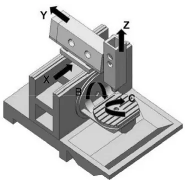
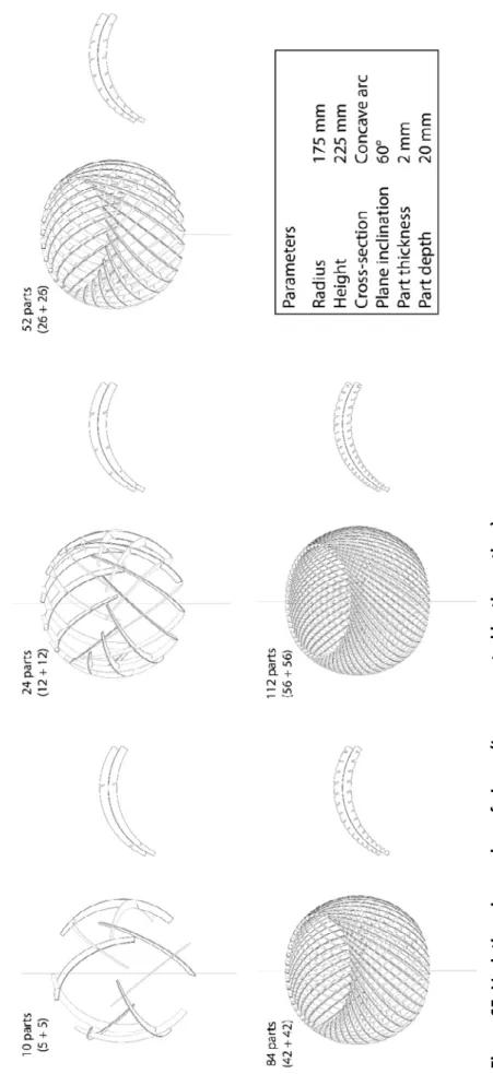
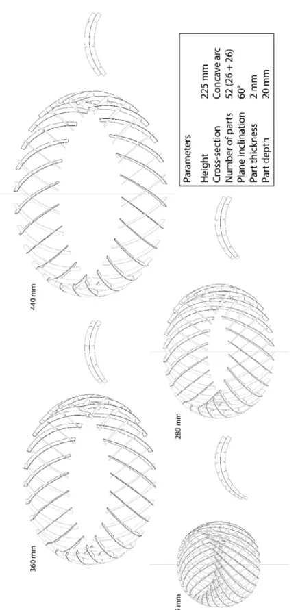
Figure 1. Winery of Gantenbein in Fläsch, Switzerland ... 15 Figure 2. Torus to teacup deformation ... 20 Figure 3. Landesgartenschau Exhibition Hall in Gmünd, Germany ... 21 Figure 4. Geometric primitives ... 23 Figure 5. Pantheon interior view ... 27 Figure 6. Glashaus in Cologne, Germany ... 28 Figure 7. US Pavilion at Expo ’67, Montreal, Canada ... 30 Figure 8. Palazzetto dello Sport in Rome, Italy ... 30 Figure 9. 30 St. Mary Axe Tower in London, UK ... 31 Figure 10. Tornado Tower in Doha, Qatar ... 31 Figure 11. Canton Tower in Guangzhou, China ... 32 Figure 12. Church of Jesus Christ the Worker in Atlantida, Dieste ... 34 Figure 13. An exemplary hyperboloid surface under construction by Candela ... 36 Figure 14. Operable shades of Milwaukee Art Museum ... 37 Figure 15. Ysios Winery in Laguardia, Spain ... 37 Figure 16. Sequential Wall ... 38 Figure 17. La Sagrada Familia in Barcelona, Spain ... 40 Figure 18. Einstein Tower in Potsdam, Germany ... 41 Figure 19. Notre Dame du Haut in Ronchamp, France ... 41 Figure 20. Guggenheim Museum in Bilbao, Spain ... 42 Figure 21. An example of a 2nd‐degree Bezier surface with control points ... 43 Figure 22. The figurative depiction of industrial revolutions ... 49 Figure 23. Maison Dom‐ino ... 52 Figure 24. Maison Citrohan as a mass‐produced house ... 53 Figure 25. Dymaxion House ... 54 Figure 26. Diagram of Le Corbusier’s “The Modulor” ... 55 Figure 27. Habitat ’67 in Montreal, Canada ... 57 Figure 28. Hangar for Italian Air Force in Orvieto, Italy ... 58 Figure 29. Twisting brick façade of Keller AG Headquarter in Pfungen, Switzerland ... 62 Figure 30. Three alternatives of Tables Projectives ... 63 Figure 31. Walt Disney Concert Hall in Los Angeles, USA ... 64 Figure 32. Experience Music Project in Seattle, USA ... 65 Figure 33. A five axes CNC machine diagram ... 66 Figure 34. A 6‐axis CNC robot arm ... 67 Figure 35. Robotic Wood Tectonics Project ... 68 Figure 36. Partial rapid‐prototyped house construction detail ... 69Figure 37. A topography model made by contouring ... 74 Figure 38. mTABLE ... 75 Figure 39. Notre Dame du Haut’s roof construction detail ... 77 Figure 40. Yokohama International Port Terminal in Yokohama, Japan ... 78 Figure 41. Metropol Parasol in Seville, Spain... 79 Figure 42. Yokohama International Port Terminal Interior ... 80 Figure 43. Theatre Agora in Lelystad, the Netherlands ... 81 Figure 44. Horten Headquarters Building in Copenhagen, Denmark ... 82 Figure 45. BMW Bubble in Frankfurt, Germany ... 84 Figure 46. Forming of acrylic‐glass elements ... 84 Figure 47. Quadripartite relation ... 86 Figure 48. Unité d’Habitation in Marseille, France ... 90 Figure 49. Sydney Opera House and a construction detail ... 91 Figure 50. Nationale Nederlanden Building in Nové Město, Czechia ... 93 Figure 51. New York by Gehry ... 94 Figure 52. Heydar Aliyev Center in Baku, Azerbaijan ... 95 Figure 53. Serpentine Gallery 2002 in London, UK ... 97 Figure 54. National Aquatics Center in Beijing, China ... 99 Figure 55. A panel of Winery of Gantenbein ... 101 Figure 56. Vault prototype at ETH Zurich ... 102 Figure 57. Flowchart of the algorithm ... 106 Figure 58. Formation process ... 108 Figure 59. Horizontal Line Test ... 109 Figure 60. Slit formation detail ... 109 Figure 61. Assembly process ... 111 Figure 62. Assembled structure ... 112 Figure 63. Pieces' intersection and filler plate connection detail ... 113 Figure 64. Variations in cross‐section ... 116 Figure 65. Variations in number of pieces ... 117 Figure 66. Variations in revolution radius ... 118 Figure 67. Variations in inclination angle of pieces ... 119 Figure 68. Variations in piece thickness ... 120 Figure 69. Variations in piece depth ... 121 Figure 70. Multi‐layered formation ... 123 Figure A1. Grasshopper algorithm screenshot ... 144
CHAPTER 1
INTRODUCTION
“Architecture starts when you carefully put two bricks together. There it begins.” Mies van der Rohe (1959) The relation of two minute constituents of a whole may seem like a simple characteristic for any three‐dimensional construct. However, it is through countless repetitions of this feature among constituents, the “parts,” that make up whole, the “form.” This study tries to shed light on the relation of elements among different scales of implementations in architecture by investigating “form” and “part.” The smaller quality of “part” when compared to “form” already denotes some qualities for the two. While “part” is the smaller constituent, “form” signifies a totality. This differentiates both fundamentally, but also make the two dependent to each other. A “part” is inevitably the building component of a “form.” For architectural form, besides the “parts,” geometry can also be considered as another core component. The increasing potential of geometric constructibilitythrough the introduction of computer‐aided design and manufacturing (CAD / CAM) technologies together with the developments in the material industry have made possible for architects to design and build architectural forms with a magnified range of possibilities. In addition to the expansion of geometric possibilities, CAD / CAM technologies also bring forth an increased concern in terms of economic criterion, which results with the introduction of “rationalization” and “discretization” of freeform geometries. Both concepts are outcomes of “standardization” and have increasing amounts of influence for architecture in CAD / CAM. Although architecture is previously familiarized with “standardization,” it expanded its scope with the introduction of the term “non‐standard,” through the potentials and requirements of newly introduced architectural forms. Although “standard” and “non‐standard” may seem as counterparts, in terms of rationalization and discretization, they both share a common ground of “form” and “part” relation. Therefore, to understand the concepts “standard” and “non‐ standard,” the relation between “form” and “part” is investigated in this study. Both “form” / “part” and “standard” / “non‐standard” are studied separately in this study, and it is an attempt to introduce a novel approach to architectural “form” and “part” analysis.
1.1. Research Objectives and Scope of Study
In contemporary architectural experimentations, there is a propensity to standardize “parts” for attaining non‐standard “forms.” The uncharted quality of non‐standard is still denoted as a significant challenge for architecture and any attempt to resolve undefined geometries is regarded as a valuable exploration. In “Digital Architecture Now,” printed in 2008, numerous approaches in non‐standard architectural “forms” are presented (Spiller), leaving aside the implementation processes and focusing only on the generation and visualization of “forms.” However, when projects involved in the three collections of “Fabricate Triennial” ‐ the state of art, showcase conference for universities and architects‐ (Sheil & Glynn, 2011; Gramazio, Kohler & Lengenberg, 2014; Menges, Sheil, Skavara & Glynn, 2017) are analyzed; one can see the distinct development of architecture in the second decade of the 21st century, through CAD / CAM techniques. The primary attitude of all these projects display transformations from mere formal approaches to efforts to overcome limitations of the “form” by proposing strategies that demonstrate extensive production techniques employing various materials. The dramatic alteration in architecture points out to a highly critical shift from “form” to “part” in architectural design processes. In architecture, there has always been a need to assemble any “form” through discrete “parts” because of the large scales of buildings. This necessity has given precedence to “parts” in architecture. The formal, functional, scale‐wise qualities and requirements of “parts” differ with every project and in this respect, the concept of “standard” has to be redefined for each “form” and “part.” Theinterrelation of two elements inevitably introduce a “joint,” but joints have not been included into this study. Although they have highly significant qualities within architecture both at the scale of “form” and “parts,” the joints need a more detailed and specially devoted study. The primary objective of this study is to develop a scheme for understanding the “form” and “part” relationship in architecture through “standardization” and “non‐ standardization.” The contradictory and complementary nature of the latter two brings forth the possibility of analyzing “form” and “part” in an extensive manner. The study also covers the formal characteristics of the concepts besides their historical and theoretical contexts. The analysis is realized through a quadripartite relation, generated by the permutation of the concepts “form” and “part,” together with “standard” and “non‐ standard,” creating “standard form – standard part,” “standard form – non‐ standard part,” “non‐standard form – standard part” and “non‐standard form – non‐standard part.” The four conditions of the quadripartite relation create diverse qualities in architectural terms with each partition having distinctive existences. The analysis of “forms” and “parts” present a valuable knowledge about architecture and the way it is designed and constructed. The secondary objective is to develop a unique discretization scheme by utilizing the findings acquired from the quadripartite relation’s analyses. The secondary objective is implemented through a model, which is devised by the author. The model is utilized by adopting sectioning technique for surface structures to increase
material efficiency and standardization, and it is specifically designed for surfaces of revolution infrastructures to support the ideas developed throughout the thesis.
1.2. Structure of Thesis
After the introduction, the second chapter starts with the definition of terms, “form” and “part.” It is followed by further analysis of “form,” by tracing the concept’s historical background. Apart from being a visual concept, “form” has been investigated among different readings all tied to architecture. It is through this understanding the following sub‐chapter is formed, “the generation of part.” The strong connections between the “form” to architecture, brings forth the “part” concept as the generator of “form,” hence the tectonic dependence of “part” and “form.” Topology is included in the study as an important concept, and it is for this reason that both “form” and “part” is dealt in a topological manner, instead of a case‐specific geometrical approach. This enabled the analyses to have a much broader quality. Platonic solids are studied to form a common base for further geometric considerations to strengthen the topological stance of the thesis. It is then followed by a group of more complex geometries, surfaces of revolution, ruled surfaces and freeform surfaces. The increasing complexity of the four subchapters illustrates the geometric qualities they govern in a much clear and distinct way. The givenexamples demonstrate the formation of geometric constituents of the architectural examples, the “form” and the “part.” The examples have not been limited with specific periods of architecture, but instead examples from different periods ranging from antiquity to contemporary architecture are presented, because of the concepts’ anachronistic qualities. The third chapter mainly covers two important terms for architecture, “standard” and “non‐standard.” The “standard” is investigated in detail as the main factor for the accomplishment of modern architecture in the 20th century. Mass‐production is also investigated as a participatory actor for the concept “standard” and “standardization.” Their implementations as the proof‐of‐concepts are included to exemplify the means of interpretation in the mid‐20th century. “Non‐standard,” as presenting vast potentials in “form,” is also investigated, with its several implementations. Both “standard” and “non‐standard” are supported by the concepts “rationalization” and “discretization.” As a means for generating “parts” from “forms,” they are explained in detail by discussing their potentials through different types. This part is followed by demonstrating the techniques used –i.e., contouring, sectioning, tiling, and forming– in the surface generation and manufacturing through the concepts of “form” and “part.” The chapter concludes with the analysis of the factors that are vital in the generation of forms in computer‐ aided design and manufacturing (CAD / CAM). Although the titles denote the opposite except for the last sub‐section, computer‐aided design is the underlying theme of this chapter. Both terms standard and non‐standard are also investigated via CAD tools and concepts.
Succeeding the explanation of the fundamental terms “part,” “form,” “standard” and “non‐standard,” the fourth chapter introduces a quadripartite relation, formed through the multiple relations of the terms of the second and third chapter. Both “form” and “part” are analyzed in terms of ‘standard and ‘non‐standard.’ Each variety of the two groups are analyzed regarding formal, economic, tectonic and computational criterions. This provides the basis for evaluating these four different variations, while also comparing each type of formation to each other. All four types of existence are exemplified both through built architectural examples and unbuilt geometric relations. The chapter concludes with the overall assessment of the differing interrelations of the two sets of terms. Built upon the criteria proposed in the previous chapter, the fifth chapter introduces the model as a demonstration tool for the concepts aforementioned in the thesis. Besides exemplifying the explained concepts, the suggested model tries to produce elucidations to the problems of the “form” and “part” relation. By defining the parameters like material, scale, economy, and function; the devised model is explained in detail. The model deals with the surface structures of surfaces of revolution. Two variations are manufactured and assembled for demonstrating the possible material existences of the model and the parameters of the proposed model are also studied extensively in the following subchapter through numerous variations.
CHAPTER 2
FORM AND PART
“…for we think we know a thing only when we have grasped its first causes and principles and have traced back to its elements.” Aristotle (Phys. I.1, 184a12‐14, trans. Waterfield) A three‐dimensional construct, whether it be a nanometer scale engineering marvel or a kilometer‐high skyscraper, would be a combination of numerous constituting elements. By joining those constituents, an assembled construct is attained. The construct’s complexity is dependent on the degree of variations in its constituting elements and their relation to the whole. Any three‐dimensional construct would be fit to give as an example, yet a simpler, maybe the simplest, one would be a jigsaw puzzle. A puzzle consists of numerous pieces, making a single whole, with the pieces’ correct set of interrelations. While the pieces are the constituting elements, the finished puzzle is a three‐dimensional construct. Although this 3d construct is perceived as a single whole when the puzzle is complete, one would still be able to identify every piece of the puzzle.
In any three‐dimensional construct, while the size of both the construct and the constituting elements may vary, there is a hierarchical scalar relation in between the two. In scalar terms, the constituting elements would always be smaller than the whole, and they would build up larger wholes by coming together. The number of constituting elements may vary, but this would not affect the scalar comparative relation of the two. The construct can also be made from a single forming element, making the size of the whole and the element equal. An assembly can be divided into numerous constituents and continued with the additional division of the constituents. If the disintegration of the components would be repeated, in the end, one would attain mono‐material constructs. Otherwise, it signifies the possibility of further identification of lower levels of constructs and analyses regarding constituent and whole relation. Therefore, a three‐dimensional construct can be made from constituents, which have also been formed from further components, making all constituents separate wholes. This chain of formation can lead to much more complex relations, but still preserving the hierarchy in all levels of associations of the two. However, it should be noted that the degree of differentiation remains in the physical limits of materials, neglecting the chemical qualities they have. An architectural project consists of several diverse systems, i.e., static, mechanical, electric, etc. We can say that is made up of those separate systems, but we cannot denote those systems as singular entities. These systems consist of highly complex diverse sets of mechanisms with multiple entities building up larger wholes in various hierarchic relations. While an architecture undergraduate can express an
architectural project as an arrangement of spaces with specific functions, a contractor would denote the same project as an integration of several engineering assemblies. A mechanical engineer would interpret the exact same project as a combination of numerous mechanical systems. This variability of interpretation of the same concept by different subjects signifies the possibility of diverse understandings. However, all the readings above consist of some constituting elements and a three‐dimensional construct at the end. This diversification of subjects clarifies the notion of a hierarchy of construct’s and elements’ relation. Within this perception, this study introduces an analytical approach to architectural projects by investigating the forms of the constructs and the constituents of design in various scales. Within the context of this study, the elements that make up the larger whole are denoted as the “parts” and the larger whole, the three‐ dimensional construct, as the “form.” It is a conscious choice to use the term “form” instead of “whole,” for the latter would still signify the properties of the “part,” whereas the former indicates a whole new set of qualities. Both “form” and “part” is analyzed in a geometrical approach. Although a “form” may consist of some diverse “parts” regarding material, function or form, various levels of abstractions are still possible. Through an abstract interpretation of the overall “form,” it can be considered as a single geometry. Considering an architectural project as a single geometry signifies a deduction of many groups of constructs, leaving aside further possible analyses. However, this type of reasoning allows a concise conclusion about the “form” of the analysis. In the cases of this study, the “form” has been thought on both scalar bounds; as the
whole project and as a single constituent. The scalar variation allows an inductive reasoning of the findings.
2.1. The Concept of Form
Aristotle had widely studied the idea of form as early as the fourth century BC (Aristotle, Phys. I.2, trans. Waterfield). His approach mainly covers the aspects, constituents, and qualities of form. Although Aristotle’s approach is more of an ontological and philosophical one, it is beneficial to refer to his analysis. Aristotle’s concept of form mainly deals with the form’s constituents to reach up to an overall understanding of form and tries to discern the logical components of the whole to grasp the “overall message” (Aristotle, Phys. I.1). While Aristotle had attempted to define the logical elements of form, this study tries to disintegrate the bodily components of a “form.” Within the field of arts, “form” is considered as one of the main building blocks, together with line, shape, value, space, color, and texture (Crane, 1900). In its broadest and simplest terms, a form is the overall shape of a thing (Langer, 1957). Usually, while “shape” denotes a two‐dimensional geometry, the term “form” denotes three‐dimensional properties. All three‐dimensional objects, regardless of their size or complexity, have a form. In architectural terms, form is closely related to the concept of space (Jirousek, Textiles, & Apparel, 1995). An architectural form would and should imply a spatial quality and configuration. Any interrelation of two identities, the “parts,” brings forth a combination of the two, producing a new orderwith a novel “form,” whether it has a useful function or not (Aristotle, Phys. I.2, 185b5‐18). Aristoteles talks about a human and a human statue by noting the differences in between the two and concludes that although they are both shaped the same, they cannot be considered as equal entities (Phys. II.2, 193a12). However, for this study, a human being and a statue are equal in terms of “form,” and this study deals with the form of both, together with the constituents of it. In other words, the function is not considered as one of the determinants for the evaluation of forms, unless function has been utilized by the designer as a determinant for the most basic constituent of “form,” the “part.” This study tries to formulate an analytical method to understand the qualities of the building blocks of a whole within the framework of the formal characteristics of the totality itself. In one of the first treatises on architecture, “Ten Books on Architecture,” Marcus Vitruvius Pollio (c. 90 ‐ c. 20 BC) talks about a broad variety of topics that range from town planning to details of pavements and overall conceptions of geometry (Vitruvius, 2016). Here also specifies the exact details for all his descriptions through materials or details, as if they are culinary recipes. However, “form” is not a criterion to consider for Vitruvius. Although Vitruvius talks about the formal attributes of capitals of the period in a geometrical and descriptive sense, there is an instructive stance throughout, an inevitable consequence of the relation between form and technique. Unless the constructive method of a particular “form” is not known, it cannot be built. “form” is a resultant factor of the construction technique.
One of the most significant and critical principles on “form” has been propagated by Louis Sullivan in 1896. His conception of “Form follows function” has affected and continues to affect architecture since then (Sullivan, 1896, p. 408). It denotes the interrelation of form with the function, limiting the form only to the outcomes of the notion of function. However, one cannot consider function as the sole determinant of form. Function indeed denotes a formal typology that is dependent on itself, but it would not be enough to consider it as the single utmost criteria. Therefore, form owes its existence to certain other factors, such as technique, material, economy, and aesthetics.
2.2. Generation of Part
Aristotle, in his seminal Physics, also talks about the relation of the elements and the whole they make up (Phys. I.4, 187b13). In order to assemble a large whole, it is essential to have discrete parts. The aim and need for reaching to a larger‐scale entity make the “part” an indispensable constituent of “form.” Through this approach, together with the “form” that is said to be designed, the designer also creates the “part,” even before the “form.” This notion creates a dependency in‐ between “form” and “part,” defining all the attributes of the “form.” In this respect, the material, color, texture, and size of its constituents, together with the ease of manufacturing and economy of a “form” are all dependent on “part.” While for a masonry wall, bricks would be the “parts”; for a structure clad with steel, the steel plates would be. It can be seen that “part” is considered as the simplest repeating constituent of the design; but another approach is also possible,in which the “part” is considered as an intermediary element making up the “form.” The term piece is not used in this study, but instead “part” is chosen. Piece denotes a single entity that may lead to an upper degree of totality and the same is valid for the “part,” but they are differentiated by the “part’s” possible existence of a larger construct. A “part” may consist of several other “parts” and it is not the case for a piece. A piece denotes the simplest constituent of a whole, whereas a “part” also has the potential to signify an intermediary component of a “form.” Therefore, any piece will also be a “part,” but not vice versa, making the piece a subset of “part.” The approach of this study does not necessarily decompose a “form” to its most basic “parts,” hence the pieces, but takes an analysis specific stance. By breaking the decomposition process at an intermediary stage, a new level of analysis becomes possible. In the example of Winery of Gantenbein by Fabio Gramazio and Matthias Koehler (2008) the structure is constructed from thousands of brick elements, each positioned and oriented individually by robotic arms. At first glance, the bricks can be considered as the “parts” and the façade as the “form.” It should also be noted that each brick element can also be seen as a “form” by itself. However, if scrutinized, it would be seen that there exist intermediary constituents of the façade: the rectangular frames creating intermediary “tiers of assemblies” (Kieran & Timberlake, 2003, p. 19). While the façade still being the final “form,” the frames also become intermediary “forms” built by the bricks. The frames would then be considered as the secondary “parts” of the design and the bricks be counted as primary. Here, the first and second ordering of “parts” is a result of the hierarchical
relations and sequence of formation for each group of elements. This approach explicitly demonstrates a different degree of abstractions for “form” and “part.” Figure 1. Winery of Gantenbein in Fläsch, Switzerland (Gramazio & Kohler, 2008, p. 100). Although it has been said that the constituents, namely “parts,” can be disintegrated until they are composed of a single material, it is not the only criterion to define the limits of “parts.” It is the way a “part’s” constituents are arranged, in relation to each other, namely their physical relationships that are being analyzed in this study. With the introduction of computer‐aided design (CAD) and computer‐ aided manufacturing (CAM) techniques, a “part” can be manufactured by infinitely many number of constituents, each designed and fabricated separately. Although the production process of a rapid‐prototyped object would be composed of a single material, it still can govern a part wise formation. Then the prototyped objects
would be “parts,” in which every one of them is made up from many “parts” and they would assemble the “form.” This makes up the “form,” an assembly of multilevel “part” and “part” relations. For the mono‐material constructs, as there does not exist a “form” to “part” relation, the “form” and “part” relationship is also altered. A contemporary example in this context would be an object manufactured by rapid‐prototyping. As the fabricated product would be composed of a single material, it cannot be stated that a “form” and “part” relation exists like in an ordinary construct. On the contrary, the concepts “form” and “part” are fused into each other, and there does not exist a “part” apart from the overall “form” and vice versa. Although a three‐dimensional form cast from concrete would be considered as similar to the given an example above, a higher level of abstraction will present an entirely different point of perspective for analysis. Any concrete form would be a single three‐dimensional entity with a single “part,” but to cast it, a formwork construction is needed. Consequently, the formwork would be composed of more than one discrete element, which transforms the concept of “part” to a new level. It is now a constituent of the “form” not as an integral counterpart but as an essential component for the pre‐formation phase. Hence, the concept of “part” does not have to be limited only with the end result, but instead, it can also include the production procedure, entailing the whole lifecycle of the “part.” Within the context of this study “part” is considered to be the most central quality a “form” houses. Although at first, it is the overall “form” of a structure that attracts
attention, through a more comprehensive perception and analysis, one would be aware of the constituents that make up the whole, and it is the relation in between those “parts” that materialize the “form.” The “parts” may be at any scale, maintaining the scalar hierarchy in respect to “form.” The definition of a “part” may be an outcome of several factors. While the designer’s intentions can be the most central, it may also be the scalar limitations of materials or manufacturing techniques that bring forth the necessity of introducing the concept of “part” and this also adds the necessity to interrelate each “part” with its neighboring “parts.” To connect the “parts” a joint is needed, and the joints would create the interrelation of “parts” with each other.
2.3. Tectonic Dependence of Form and Part
Tectonics, etymologically Greek, from tekton meaning carpenter or builder, is an architectural topic dealing with how two distinct elements come together (Frampton, 1995). Starting from the 19th century with the definitions by Karl Böttticher as ‘complete system binding all parts of the Greek temple’ and by Gottfried Semper as “lightweight, linear components,” tectonics can be considered concisely as the poetics of construction (Frampton, 1995). Tectonics has been defined as the “art of joinings” by Adolf Heinrich Borbein, in 1982 (as cited in Frampton, 1995). Borbein has included joinings at all scales, ranging from objects to artworks, together with building parts to this definition. Although the term indicates an artistic stance towards the joinings, it is merely a technical one.In a tectonic analysis, the joining of two hierarchically equal parts that are vastly repeated throughout a design is taken into consideration. Joining two discrete elements would create a new entity in some higher hierarchical scale, and tectonics focuses on the relation of the initial two, but not of the hierarchically upper one, the whole, with the initial two’s, “parts.” In hierarchical terms, “part” is the main constituent of the overall “form,” yet it can be said that there exists a different and particular type of tectonic dependence between the two. While a tectonic relation signifies two hierarchically equivalent elements are creating a larger whole, the tectonic relationship of “form” and “part” denotes a dependence. The tectonic dependence criterion of the “form” to “part” represents a unidirectional link in between the two, making the “form” tectonically dependent to “part.” The formal, material or technical aspects of a “part” directly affects the corresponding qualities of “form,” hence the dependency of “form” to “part.” In tectonics, instead of the size and dimensions of elements, relations among them are investigated, and it is the fundamental aspect of tectonics. Therefore, the methodology of tectonics can be considered as a qualitative and topological stance instead of a quantitative one. Even the joining of two timber elements denotes certain aspects for tectonics. How the elements are brought together, the final form of the joining, the geometrical characteristics of both the “parts” and the assembly are all unique norms for tectonics. All the aspects mentioned denote distinct qualities, but none of them indicates scalar qualities.
2.4. Topology as a Tool for Inspecting the Formal Aspects of Parts
The concept of topology is included into the study to investigate the geometric qualities of “form” and “part” beyond the scalar limitations of the studied examples. Topology is a mathematical term, and it is used in this study for its close relation with geometry (Choquet, 1966). Topology is the science dealing with the geometric structure of shapes, instead of their size, shape or curvature (Carter, 1995). In topology, any variation of a geometry attained through actions like deforming, twisting and stretching is identical to each other but tearing or gluing creates a topologically different geometry (Firby & Gardiner, 1991). Like topology, typology also deals with the shared formal qualities among examples. Typology creates groupings under some predetermined concepts like function, material or cultural values. However, topology is solely interested in the geometric qualities of forms without any added value. Therefore, topology attains a higher level of abstract and geometrical analysis, whereas typology often comprises additional aspects. The absence of such points in topology allows the analysis to have a more geometric stance, allowing to focus on the form and shape of designs. Similar geometric approaches have been taken in typology (Caniggia & Maffei, 2001; Krier, 1992; Onat, 1991), but there was always at least one coalescent factor besides geometry, diminishing the analyses’ formal effects. A formal and topological analysis of “parts” together with the overall “form” brings forth possibilities of evaluating architectural projects denoting a geometric approach to design.In topology, the most basic example given to demonstrate the qualities topology offers is the teacup attained from a torus. By stretching and deforming a torus, one can end up with a teacup geometry (Figure 2), but it is topologically impossible to end up with a teacup from a sphere, cylinder or cone unless the geometry is torn up to create a hole in it. Two forms with identical topologic properties are called homeomorphic. In the given example, torus and teacup are homeomorphic geometries. A homeomorphism is derived from Greek words homoios and morphē, meaning “similar” and “form” respectively and it is a subdomain of topology, focusing on the morphological qualities of geometries (Firby & Gardiner, 1991). An instance of a homeomorphic entity would be entirely different in terms its dimensions but still topologically identical with the rest of its variations and counterparts (Kolarevic, 2003). Figure 2. Torus to teacup deformation (Lynn, 1999, p. 22). “Landesgartenschau Exhibition Hall,” designed at the Institute for Computational Design, Stuttgart, in 2014, is a plywood structure with a single space. Topologically the form of the structure is an elongated sphere, sliced from both sides to create entrances and openings. The outer surface is panelised by planar hexagonal plywood elements, and there is a total of 243 unique panels, which form a lightweight curvilinear blob‐like form. There are minute dimensional
differentiations among panels, and they are homeomorphic. Hence every part is equal in topological terms. Figure 3. Landesgartenschau Exhibition Hall in Gmünd, Germany (Menges, Schwinn, & Krieg, 2016, p. 113). For this study, criterions like a number of faces, edges, and vertices of the geometries are considered as topological properties. In other words, intrinsic geometric and topological properties of the forms have been considered as the primary concern, leaving aside scalar quantities, reaching to a homeomorphic level of analysis. As the design process has shifted mainly from designing forms to designing relations (A. Kilian, 2006), the topological approach has become a vital element in analyzing and comprehending the operations and outcomes of design, preventing one to fall into the limitations of aesthetic and formal judgments for single instances of design elements. While a “part” can be considered as a topological, homeomorphic entity, a “form” can also be considered likewise. This allows the consideration of both in a more generic manner, leading to the interpretation of the examples given throughout the thesis in a broader sense. In this study, the concept of homeomorphism has been
used as a methodological analysis tool for the “form.” When a “form” is designed for the manufacturing phase, its constituent “parts” —if there are any— are also designed and determined. A variation in the “form” would only differentiate the `parts` in a topological manner. Through variation, some parts’ dimensions may change, but “parts” would be still homeomorphic. Any alterations in the “form” would not necessitate to fundamentally alter the “part” as long as the topological qualities of the relations in between “parts” are not differentiated. On the contrary, any change, whether minute or dramatic, in one of the intrinsic qualities of a “part” unequivocally influences the utmost scale of the “form.” The material, size, cost, and a number of the “parts” can be considered as several factors in this chain of effects. Therefore, “part” is the primary determinant of the “form,” hence the proposed saying “form follows part.”
2.5. Geometric Formations in Architecture
Although architectural instances have varied dramatically throughout the ages in terms of geometry, the core relation of “form” and “part” has remained as the most significant formal property architecture governs and both “form” and “part” need deeper investigations to grasp their relations and geometrical qualities. The following four subchapters demonstrate different types of geometries used in design in a homeomorphic manner, characterized by their differing types of geometric formations. Beginning with the simple geometric elements, which form the essential constituents of architecture, surfaces of revolution and ruled surfaces are also included as initial geometric, together with the formal explorations of freeform surfaces.2.5.1. Simple Geometric Elements
In Towards a New Architecture, Le Corbusier describes the ancient Egyptian, Greek, and Roman architecture through five noble forms; cylinder, pyramid, cube, prism and sphere (2013). His approach was certainly a homeomorphic and topological one as Corbusier omits the scalar qualities of the elements employed when describing the examples of the Classic Era. Branko Kolarevic also refers to Le Corbusier’s sketch to point out the significance of those geometric elements with the geometric “primitives” used in digital CAD software (Le Corbusier, 1931 as cited in Kolarevic, 2005) (Figure 4). The constant quality of geometric elements for more than 2000 years present the significance of geometry and its topological stance in architecture. Figure 4. Geometric primitives (Le Corbusier, 1931: 159). Through “transformative design,” one can attain a shape on any scale from those five elements. By stretching, deforming or other topological operations, hencekeeping the intrinsic formal qualities constant, countless forms can be created (Ching, 1996). The transformation process of a geometry allows the generation of endless alternative forms. Additive transformation allows new additions to the initial shape (Ching, 1996) and alters the topological qualities of a shape. It may also be a combination of parts created through transformative design. There also exists subtractive transformation, in which the designer removes parts from an initial primitive geometry to end up with a more complex form. It is through the transformation and combination of cubes that have created the most examples of modern architecture. It is for sure that there exist numerous other factors, which have affected the causality for the selection of the cube as the initial point (Frampton, 1995), but in geometrical terms, the end results can be classified as products of transformative and additive design. As additive transformation alters the topological qualities of a geometry, it can be through those types of alterations to attain geometries beyond topological limitations. The problem of creating a teacup from a non‐torus shape, like a cube, can be overcome through additive or subtractive design approaches by connecting several of those elements to each other to create a closed chain‐like form or tearing up the geometry and attaining an orthogonal torus shape (Firby & Gardiner, 1991). As all those simple geometric elements are closed surfaces, they are also considered as solids or masses (Corbusier, 2013). On the contrary, in contemporary architecture, with the advancements in mathematics and geometry, the solid based interpretation of design has transformed into a surface based one (Pottmann, Eigensatz, Vaxman, & Wallne, 2015). This shift from solids and masses to surfaces
has dramatically evolved the examples of architecture. Within the context of this change, following subchapters exemplify the geometric qualities of different types of surfaces commonly used in architecture.
2.5.2. Surfaces of Revolution
Surfaces of revolution present a vast degree of possibilities, because of their relatively complex formations, when compared with orthogonal geometries. Surfaces of revolution have always been an integral part of architecture despite their curvilinear forms. The sphere, the cylinder, and the cone can be considered as subsets of surfaces of revolution. Any dome with a circular‐plan can be denoted as an implementation of surfaces of revolution. The constant curvature of a surface of revolution has been the key criterion for making it a constructible form. Either by creating the cross‐section and revolving it around the center or by building successive circular plans on top of each other, a surface of revolution can be constructed with relative ease. While a simple cross‐section for a surface of revolution would generate a considerably simple formation, a complex one would end up with a highly intricate surface geometry. Geometrically, a surface of revolution can be generated by revolving a cross‐section curve around an axis (Pottmann, 2007). Depending on the characteristics of the cross‐section, straight or curvilinear, a surface of revolution can either be single or double‐curved respectively. By having a vertical axis of revolution, if the cross‐ section is a straight line, the end result would be a cylinder, and if it is slanted, a truncated conical form would be attained. The curvilinear quality of the cross‐sections presents various alternatives of double‐curved surfaces, and even a spherical form can be generated by using a semicircle as the cross‐section. A surface of revolution would have a circular‐plan layout as long as the axis of revolution is vertical. If the axis is horizontal, the plans of the surface would have diverse possibilities that range from a rectangle to curvilinear outlines. Domes have played a central role in architecture throughout the history, and they can be denoted as typical instances of surfaces of revolution. As they are structurally stable forms, they had been implemented in many materials, scales, and functions. Although dome‐like shelters are dated back as early as 400,000 years ago (Pottmann, 2007), one of the most significant examples of domes is the Pantheon in Rome, Italy and it was designed by Apollodorus of Damascus in 116 AC (Figure 5). It is one of the most dominant buildings in the history of architecture. Despite its historically‐laden qualities, for the scope of this thesis, a geometrical analysis is made. To define Pantheon geometrically, noble forms including a triangular prism, tympanum, raised on 20 cylindrical columns defining the portico, the rotunda as a cylinder and the dome as a hemisphere with an opening on top, the oculus may be employed (MacDonald, 2002). The hemispherical shape of the dome is a typical example of a surface of revolution with an arc as its cross‐section. Although the “parts” of Pantheon cannot be spotted with ease, as it has an unreinforced concrete structure, the interior coffered ceiling pattern of the dome is designated with a quadrilateral subdivision that is repeated throughout. Therefore, although the quadrilaterals are not constructive elements of the dome, they can be indicated as “parts” geometrically. There are 5 rows of quadrilaterals inside the
dome and each quadrilateral is repeated 28 times. It is certain that the unreinforced concrete dome cannot be denoted as a surface, geometrical properties of a surface of revolution have been used to its extent with its geometry and the quadrilaterals of Pantheon’s dome. There are much more examples of surfaces of revolution in great structures throughout the history of architecture with similar qualities to Pantheon. Figure 5. Pantheon interior view (Marder & Jones, 2015, p. 18). One of the first examples of a dome built in the 20th century was the Glashaus, designed by Bruno Taut in 1914. Glashaus was a pavilion at the Cologne Deutscher Werkbund 1914 (Nielsen, 2015) (Figure 6). The structure’s dome was a crude surface of revolution because of its quadrangular panels all around, but the repeating panels at every level depict typical characteristics of a surface of
revolution (Weston, 2004). The concrete frames had housed 14 triangular and 98 quadrilateral colored glass panels, and there were 7 types of “parts,” each repeated 14 times in the structure. The low number of variations was a result of the dome’s geometry, and the same was valid for the timber elements of the formwork (Nielsen, 2015). Glashaus was demolished at the end of the exhibition. Figure 6. Glashaus in Cologne, Germany (Nielsen, 2015, p. 2). Besides the domes, surfaces of revolutions were also implemented in circular‐ planned buildings and structures. Although a circular shape in the plan does not necessarily denote a surface of revolution, the verticality of the peripheral elements or a constant cross‐section throughout the does so. One of the most significant implementations is the Solomon R. Guggenheim Museum in New York, dated 1939, designed by Frank Lloyd Wright. The circular formation in the building is actually a continuous spiral throughout all the levels with a slightly slanted vertical exterior surface. A similar condition is also present in the interior of the structure by the introduction of a circular atrium, and the spiraling ramp connects all levels inside. Formed by the combination of varying circular surfaces of revolution throughout
the stories and an orthogonal configuration, Frank Lloyd Wright implemented surfaces of revolution in his design at their fullest extents together with the interior circular shaped atrium (Pfeiffer, 1995). Vladimir Shukhov was a highly significant Russian engineer, and he has utilized surfaces of revolution in his numerous towers at the end of the 19th century. By implementing his own patented technique, Shukhov has constructed more than 200 towers with heights ranging from 37 meters to 130 meters (Beckh, 2015). Structurally, Shukhov’s towers were all catenary frames, but the geometry they governed was surfaces of revolutions because of their circular‐plans. Due to being catenary frames, all the towers had a standard geometric formation of hyperboloid form. In his towers, Shukhov had utilized numerous vertically slanted linear elements in two opposing directions, arrayed in a polar fashion. The particular configuration of the elements created a highly stable structural organization, and Shukhov’s towers are also denoted as the predecessor of contemporary diagrid systems for the geometric qualities they govern (Ritchie, 2012). Pierre Luigi Nervi’s and Buckminster Fuller’s numerous structures should also be noted as outstanding examples of surfaces of revolution. Although Fuller’s technique is specialized for geodesic domes and patented under the same subject, both Nervi and Fuller devised unique methods for attaining surfaces of revolution. Fuller has mainly focused on spherical steel structures (Figure 7), and Nervi implemented concrete shells to their fullest extent via curvilinear formations that are not only limited to surfaces of revolution (Nervi, 1956) (Figure 8).
Figure 7. US Pavilion at Expo ’67, Montreal, Canada (Pawley & Fuller, 1990, p. 167). Figure 8. Palazzetto dello Sport in Rome, Italy (Charleson, 2014, p. 19). In 2005, Foster and Partners designed an extraordinary tower, 30 St. Mary Axe that is differentiated from its contemporaries both by its circular‐plan and cross‐section (Figure 9). The cross‐section of 30 St. Mary Axe is formed from the combination of several concave arcs, and the resultant form of the tower is a double‐curved surface (Boake, 2014). The curvature of the cross‐section has enabled Foster and Partners to attain a public plaza at the ground and various advantages in terms of aerodynamics, structure and material use (Foster & Partners, 2008). There are other towers in the shape of a surface of revolution with similar approaches, such as Tornado Tower (Figure 10) and Canton Tower (Figure 11). While the Tornado Tower
is designed by CICO Consulting Architects and Engineers, which is in Doha, Qatar; Canton Tower is designed by IBA, in Guangzhou, China and they are both built in 2008. Both towers’ cross‐sections are convex arcs, hence double‐curved surfaces similar to 30 St. Mary Axe. Figure 9. 30 St. Mary Axe Tower in London, UK (Foster & Partners, 2008, p. 273). Figure 10. Tornado Tower in Doha, Qatar (Boake, 2014, p. 71).
Figure 11. Canton Tower in Guangzhou, China (Boake, 2014, p. 10). Cylindrical buildings can also be considered as a type for surfaces of revolution in architecture, and maybe they are the most common. A constant plan repeated throughout the stories, which is a highly typical situation for residential and office blocks, together with a circular formation will inevitably create a surface of revolution, the cylinder.
2.5.3. Ruled Surfaces
Other formal experimentations have been carried out in architecture prior to the introduction of CAD technologies. Instead of arbitrary forms, geometrically well‐ defined forms were preferred because of their ease of methods of construction. Ruled surfaces, in that sense, are powerful tools for creating various types of curvilinear geometry, also providing the necessary means to construct. The formation process of a ruled surface is simple. A ruled surface can be created by extruding a straight line along a curve in three‐dimensional space, regardless of theformal qualities of the curve. Most of the ruled surfaces are developable, which also denotes the possibility of unrolling the ruled surface onto a plane without any stretching, deformation or tearing of the surface. The surface can be constructed out of this planar sheet element with bending. Whether a ruled surface is developable or not; as the generator of ruled surfaces are straight lines, among the cross‐sections taken from any point on the surface, there would be at least one cross‐section that generates a straight line (Shelden, 2002). In other words, it can be said that any ruled surface is formed from infinitely many parallel straight lines, the rules that differ in rotation in space. It should also be noted that in ruled surfaces, the rules do not intersect each other, i.e., every cross‐section is parallel to the rest, in terms of surface geometry. It is this property of ruled surfaces that makes them perfectly suitable for building curvilinear surfaces. Ruled surfaces served as a great tool for overcoming the construction problems in the realization of curved surfaces prior to the introduction of computers. Although creating ruled surfaces is not the only possible method for attaining curvilinear surfaces, it has been the most used option among other curvilinear geometries. The main reason behind this choice is the ease ruled surfaces offer in the formwork construction. The transition of ruled surfaces from conceptual design to physical existence can be through a number of different ways. A developable ruled surface can be built from sheet materials; like metal, timber, plastic or paper. Non‐developable surfaces cannot be made from sheet materials, but they can be constructed from point‐like elements, such as bricks, linear elements like successive
beams, or monocoque structures. Those techniques can also be used for formworks of ruled surfaces, followed by the casting of a plastic material like concrete. The straight lines composing ruled surfaces have enabled architects to build desired surfaces with comparable ease in the 20th century (Fallavollita & Salvatore, 2012). Eladio Dieste, an Uruguayan engineer and architect, has extensively explored the possibilities of ruled surfaces by utilizing masonry construction system. Back in 1960, in his “Church of Jesus Christ the Worker” in Atlantida, Uruguay, Dieste employed ruled surfaces, both on the building’s facades and the roof. The non‐ developable curvilinear ruled surfaces were built by bricks, hence the “parts.” By locating the geometrical construction points of the ruled surface in physical space through the structural framework and positioning each brick element accordingly, the accuracy of the surface assembly was achieved (A. Kilian, 2006). The regular pattern of the sinusoidal wave on top of the walls provides an increased bearing for the ceiling’s barrel vaults and increased slenderness for the walls thus the structural firmness, while also creating the curvilinear effect both on the outside and inside of the building (Figure 12). Figure 12. Church of Jesus Christ the Worker in Atlantida, Dieste (Anderson & Dieste, 2004, p. 56).