High-speed tapping mode imaging with active Q control for atomic force
microscopy
T. Sulchek, R. Hsieh, J. D. Adams, G. G. Yaralioglu, S. C. Minne et al.
Citation: Appl. Phys. Lett. 76, 1473 (2000); doi: 10.1063/1.126071 View online: http://dx.doi.org/10.1063/1.126071
View Table of Contents: http://apl.aip.org/resource/1/APPLAB/v76/i11
Published by the American Institute of Physics.
Related Articles
Bias controlled capacitive driven cantilever oscillation for high resolution dynamic force microscopy
Appl. Phys. Lett. 102, 073110 (2013)
Friction measurement on free standing plates using atomic force microscopy
Rev. Sci. Instrum. 84, 013702 (2013)
A correlation force spectrometer for single molecule measurements under tensile load
J. Appl. Phys. 113, 013503 (2013)
Compact metal probes: A solution for atomic force microscopy based tip-enhanced Raman spectroscopy
Rev. Sci. Instrum. 83, 123708 (2012)
Note: Radiofrequency scanning probe microscopy using vertically oriented cantilevers
Rev. Sci. Instrum. 83, 126103 (2012)
Additional information on Appl. Phys. Lett.
Journal Homepage: http://apl.aip.org/Journal Information: http://apl.aip.org/about/about_the_journal
Top downloads: http://apl.aip.org/features/most_downloaded
Information for Authors: http://apl.aip.org/authors
High-speed tapping mode imaging with active
Q
control for atomic
force microscopy
T. Sulchek,a)R. Hsieh, J. D. Adams, G. G. Yaralioglu, S. C. Minne, and C. F. Quate E. L. Ginzton Laboratory, Stanford University, California 94305-4085
J. P. Cleveland
Asylum Research, 601 Pine Avenue, Santa Barbara, California 93117 A. Atalar
Bilkent University, Ankara, 06533, Turkey D. M. Adderton
NanoDevices Inc., 516 E. Gutierrez, Suite E, Santa Barbara, California 93103
共Received 2 December 1999; accepted for publication 19 January 2000兲
The speed of tapping mode imaging with the atomic force microscope共AFM兲 has been increased by over an order of magnitude. The enhanced operation is achieved by共1兲 increasing the instrument’s mechanical bandwidth and 共2兲 actively controlling the cantilever’s dynamics. The instrument’s mechanical bandwidth is increased by an order of magnitude by replacing the piezotube z-axis actuator with an integrated zinc oxide共ZnO兲 piezoelectric cantilever. The cantilever’s dynamics are optimized for high-speed operation by actively damping the quality factor 共Q兲 of the cantilever. Active damping allows the amplitude of the oscillating cantilever to respond to topography changes more quickly. With these two advancements, 80m⫻80m high-speed tapping mode images have been obtained with a scan frequency of 15 Hz. This corresponds to a tip velocity of 2.4 mm/s. © 2000 American Institute of Physics.关S0003-6951共00兲02811-4兴
The atomic force microscope共AFM兲 has proven to be a useful tool for imaging a wide range of materials in a wide set of environments. Intermittent contact mode, or tapping mode, imaging was first introduced by Zhong et al.1 It has become the dominant mode of AFM imaging because it re-duces lateral forces between the tip and sample.2
The cantilever driven at its resonant frequency will achieve a free air amplitude determined by the drive ampli-tude, the spring constant, and the quality factor of the canti-lever’s resonance共Q兲. As the cantilever is brought into con-tact with the sample, the surface will limit the oscillatory motion. The amplitude is typically 10–100 nm and is mea-sured with a split photodetector. The root-mean-square共rms兲 amplitude of the cantilever is kept constant with a feedback loop that controls the vertical distance between the tip and the sample. In most AFMs, the feedback loop controls a conventional piezotube such that when the sample topogra-phy causes the cantilever’s rms amplitude to change, the pi-ezotube will extend or contract to restore the cantilever’s original rms value.
While the tapping mode AFM allows nanometer scale resolution with negligible frictional forces, it is encumbered by slow imaging speed. The scan speed of typical tapping mode AFMs is limited in part by the resonant frequency of the piezotube and in part by the time it takes for the oscil-lating cantilever to change amplitude. 共Other factors play a role in the tapping mode imaging speed, such as the band-width of the rms to dc converter, but these are secondary兲. For most samples, these constraints limit the tapping mode AFM’s scan speed to a few tens of microns per second. At this speed a single, moderately sized 512⫻512 pixel image will take several minutes to acquire.
We have increased the tapping mode imaging rate with two improvements. First, a faster z-axis actuator is integrated onto the cantilever. Second, an active damping circuit is ap-plied to increase the speed at which the cantilever can re-spond.
Several groups have succeeded in fabricating integrated piezoelectric bimorph actuators onto cantilevers.3–6 The bi-morph displaces the tip vertically when a voltage is applied across the piezoelectric material. This type of cantilever in contact mode allows scan speeds up to 1 cm/s.6
In other approaches for high-speed tapping mode imag-ing, Paloczi et al.7 have taken advantage of the low Q and high resonant frequency of small cantilevers in liquid to im-age with scan speeds of 52 m/s without the use of feed-back. Ookubo et al.8obtained a 225m/s speed by combin-ing the feedback signal and the error signal into a composite topographic signal. This method can indeed increase speed, but it does so at the expense of increased tip/sample force.
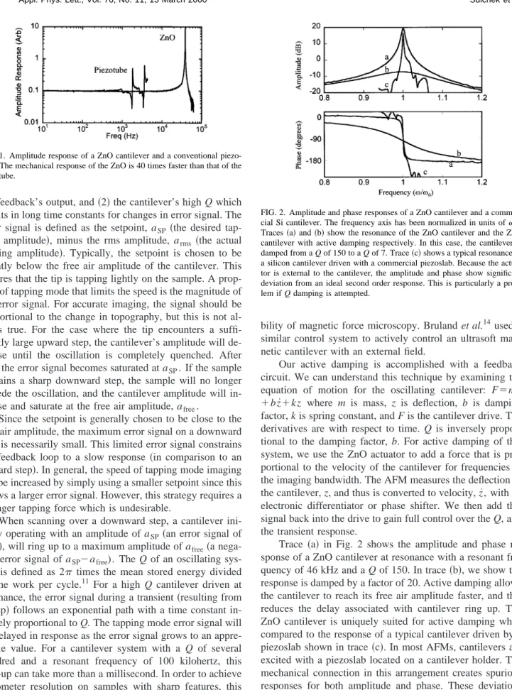
Here, we use a zinc oxide共ZnO兲 piezoelectric actuator to both drive the cantilever at its resonant frequency and to provide z actuation. The cantilever has been described previously.9 In Fig. 1, we compare the response of the inte-grated ZnO actuator with that of a typical piezotube actuator.10 The resonant frequency of the z actuator marks the point of 180° phase shift with the drive共90° at the reso-nant frequency and 90° from the feedback integrator兲. To avoid instability, the maximum gain of the feedback loop is limited such that the response at this frequency is less than one. Therefore, the z-actuator’s resonant frequency sets an upper limit on imaging bandwidth. The addition of the inte-grated ZnO actuator increases the resonant frequency by nearly a factor of 40 over the piezotube.
In tapping mode, the scanning speed is additionally con-strained by 共1兲 a small maximum error signal which limits
a兲Electronic mail: [email protected]
APPLIED PHYSICS LETTERS VOLUME 76, NUMBER 11 13 MARCH 2000
1473
0003-6951/2000/76(11)/1473/3/$17.00 © 2000 American Institute of Physics
the feedback’s output, and共2兲 the cantilever’s high Q which results in long time constants for changes in error signal. The error signal is defined as the setpoint, aSP共the desired tap-ping amplitude兲, minus the rms amplitude, arms共the actual tapping amplitude兲. Typically, the setpoint is chosen to be slightly below the free air amplitude of the cantilever. This ensures that the tip is tapping lightly on the sample. A prop-erty of tapping mode that limits the speed is the magnitude of the error signal. For accurate imaging, the signal should be proportional to the change in topography, but this is not al-ways true. For the case where the tip encounters a suffi-ciently large upward step, the cantilever’s amplitude will de-crease until the oscillation is completely quenched. After this, the error signal becomes saturated at aSP. If the sample contains a sharp downward step, the sample will no longer impede the oscillation, and the cantilever amplitude will in-crease and saturate at the free air amplitude, afree.
Since the setpoint is generally chosen to be close to the free air amplitude, the maximum error signal on a downward step is necessarily small. This limited error signal constrains the feedback loop to a slow response 共in comparison to an upward step兲. In general, the speed of tapping mode imaging can be increased by simply using a smaller setpoint since this allows a larger error signal. However, this strategy requires a stronger tapping force which is undesirable.
When scanning over a downward step, a cantilever ini-tially operating with an amplitude of aSP共an error signal of zero兲, will ring up to a maximum amplitude of afree共a nega-tive error signal of aSP⫺afree). The Q of an oscillating sys-tem is defined as 2 times the mean stored energy divided by the work per cycle.11 For a high Q cantilever driven at resonance, the error signal during a transient共resulting from a step兲 follows an exponential path with a time constant in-versely proportional to Q. The tapping mode error signal will be delayed in response as the error signal grows to an appre-ciable value. For a cantilever system with a Q of several hundred and a resonant frequency of 100 kilohertz, this ring-up can take more than a millisecond. In order to achieve nanometer resolution on samples with sharp features, this delay will limit the scan speed to a few microns per second. Our solution to this problem is to use active damping to change the cantilever’s apparent Q. Mertz et al.12developed a system for actively damping an AFM cantilever to speed up the system’s mechanical transients. Their system used a thermal bimorph actuator to apply the active control. Garbini
et al.13 extended this work by designing a controller for ac-tive modification of cantilever dynamics to improve the
sta-bility of magnetic force microscopy. Bruland et al.14used a similar control system to actively control an ultrasoft mag-netic cantilever with an external field.
Our active damping is accomplished with a feedback circuit. We can understand this technique by examining the equation of motion for the oscillating cantilever: F⫽mz¨
⫹bz˙⫹kz where m is mass, z is deflection, b is damping
factor, k is spring constant, and F is the cantilever drive. The derivatives are with respect to time. Q is inversely propor-tional to the damping factor, b. For active damping of this system, we use the ZnO actuator to add a force that is pro-portional to the velocity of the cantilever for frequencies in the imaging bandwidth. The AFM measures the deflection of the cantilever, z, and thus is converted to velocity, z˙, with an electronic differentiator or phase shifter. We then add this signal back into the drive to gain full control over the Q, and the transient response.
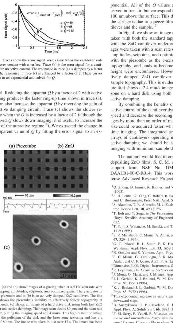
Trace 共a兲 in Fig. 2 shows the amplitude and phase re-sponse of a ZnO cantilever at resonance with a resonant fre-quency of 46 kHz and a Q of 150. In trace共b兲, we show the response is damped by a factor of 20. Active damping allows the cantilever to reach its free air amplitude faster, and this reduces the delay associated with cantilever ring up. The ZnO cantilever is uniquely suited for active damping when compared to the response of a typical cantilever driven by a piezoslab shown in trace 共c兲. In most AFMs, cantilevers are excited with a piezoslab located on a cantilever holder. The mechanical connection in this arrangement creates spurious responses for both amplitude and phase. These deviations from the ideal system make it difficult to stabilize and main-tain active control.
In Fig. 3, we show the effect of active control on the cantilever ring-up time. There we display the error signal versus time when the cantilever suddenly loses contact with the surface. These results were obtained by tapping on a bare silicon sample that was quickly retracted at t⫽0.15In Fig. 3, trace 共b兲 is the error signal for a cantilever with no active FIG. 1. Amplitude response of a ZnO cantilever and a conventional
piezo-tube. The mechanical response of the ZnO is 40 times faster than that of the piezotube.
FIG. 2. Amplitude and phase responses of a ZnO cantilever and a commer-cial Si cantilever. The frequency axis has been normalized in units of0. Traces共a兲 and 共b兲 show the resonance of the ZnO cantilever and the ZnO cantilever with active damping respectively. In this case, the cantilever is damped from a Q of 150 to a Q of 7. Trace共c兲 shows a typical resonance of a silicon cantilever driven with a commercial piezoslab. Because the actua-tor is external to the cantilever, the amplitude and phase show significant deviation from an ideal second order response. This is particularly a prob-lem if Q damping is attempted.
1474 Appl. Phys. Lett., Vol. 76, No. 11, 13 March 2000 Sulcheket al.
control. Reducing the apparent Q by a factor of 2 with active damping produces the faster ring-up time shown in trace共a兲. We can also increase the apparent Q by reversing the gain of the active damping circuit. Trace 共c兲 shows the slower re-sponse when the Q is increased by a factor of 2共although the increased Q slows down imaging, it is useful to increase the range of the attractive regime16兲. We extracted the change in the apparent value of Q by fitting the error signal to an
ex-ponential. All of the Q values are smaller than those ob-served in free air, but correspond to Q measurements taken at 100 nm above the surface. This decrease in Q when close to the surface is due to squeeze film damping between the can-tilever and the sample.17
In Fig. 4, we show an image and a line trace of a grating taken with both the standard tapping mode system 共a兲, and with the ZnO cantilever under active control 共b兲. Both im-ages were taken with a scan rate of 5 Hz, with equal tapping amplitudes, setpoints, and optimized gains. The image taken with the piezotube as the z-axis actuator does not follow topography, and tends to become unstable when changes in height were encountered. However, the scan with the ac-tively damped ZnO cantilever faithfully reproduces the sample topography. This is evident from the line traces. Fig-ure 4共c兲 shows a 2.4 mm/s image of a laser textured landing zone on a hard disk using both the fast ZnO actuator and active damping.
By combining the benefits of a fast z-axis actuator and active control of the cantilever dynamics, we can increase the speed and decrease the recording time for tapping mode im-ages by more than an order of magnitude. Imim-ages of smaller size could be acquired faster, which may allow for fast, real-time imaging. The integrated actuator has been used with arrays of cantilevers operating in parallel,18 and now with active damping we should be able to achieve large scale imaging with minimum sample damage.
The authors would like to credit Jim Zesch for his work depositing ZnO films. S. C. M. and D. M. A. acknowledge
support from NSF No. DMI-9903522 and DARPA
DAAH01-00-C-R014. This work is supported by the De-fense Advanced Research Projects Agency.
1
Q. Zhong, D. Imniss, K. Kjoller, and V. B. Elings, Surf. Sci. 290, L688 共1993兲.
2S. H. Leuba, G. Yang, C. Robert, B. Samori, K. van Holde, J. Zlatanova,
and C. Bustamante, Proc. Natl. Acad. Sci. USA 91, 11 621共1994兲.
3
S. Akamine, T. R. Albrecht, M. J. Zdeblick, and C. F. Quate, IEEE Elec-tron Device Lett. 10, 490共1989兲.
4T. Itoh and T. Suga, in The Proceedings of Transducers ’95, Stockholm
共Royal Swedish Academy of Engineering Science, 1995兲, Vol. IV A, p. 632.
5
T. Fujii, S. Watanabe, M. Suzuki, and T. Fujiu, J. Vac. Sci. Technol. B 13, 1119共1995兲.
6S. R. Manalis, S. C. Minne, A. Atalar, and C. F. Quate, Rev. Sci. Instrum.
67, 3294共1996兲.
7
G. T. Paloczi, B. L. Smith, P. K. Hansma, D. A. Walters, and M. A. Wendman, Appl. Phys. Lett. 73, 1658共1998兲.
8N. Ookubo and S. Yumoto, Appl. Phys. Lett. 74, 2149共1999兲. 9S. C. Minne, G. Yaralioglu, S. R. Manalis, J. D. Adams, J. Zesch, A.
Atalar, and C. F. Quate, Appl. Phys. Lett. 72, 2340共1998兲.
10
Dimension 3000, Digital Instruments, Santa Barbara, CA 93117.
11R. Feynman, The Feynman Lectures on Physics共1963兲, Vol. 1, p. 24–2. 12J. Mertz, O. Marti, and J. Mlynek, Appl. Phys. Lett. 62, 2344共1993兲. 13J. L. Garbini, K. J. Bruland, W. M. Dougherty, and J. A. Sidles, J. Appl.
Phys. 80, 1951共1996兲.
14
K. J. Bruland, J. L. Garbini, W. M. Dougherty, and J. A. Sidles, J. Appl. Phys. 83, 3972共1998兲.
15This exponential increase in error signal is also observed when imaging
downward steps.
16
B. Anczykowski, J. P. Cleveland, D. Kruger, V. Elings, and H. Fuchs, Appl. Phys. A: Solids Surf. 66, S885共1998兲.
17F. M. Serry, P. Veuzil, R. Vilasuso, and G. J. Maclay, in Proceedings of
the Second International Symposium on Microstructures and Microfabri-cated Systems, Chicago共Electrochem. Soc., Pennington, NJ, 1995兲, p. 83.
18
S. C. Minne, P. Flueckiger, H. T. Soh, and C. F. Quate, J. Vac. Sci. Technol. B 13, 1380共1995兲.
FIG. 3. Traces show the error signal versus time when the cantilever sud-denly loses contact with a surface. Trace共b兲 is the error signal for a canti-lever with no active control. The resonance in trace共a兲 is damped by a factor of 2. The resonance in trace共c兲 is enhanced by a factor of 2. These curves were fit to an exponential and solved for Q.
FIG. 4.共a兲 and 共b兲 show images of a grating taken at a 5 Hz scan rate with equal tapping amplitudes, setpoints, and optimized gains. The z actuator in 共a兲 is a piezotube and in 共b兲 is an actively damped ZnO cantilever. The line traces shows the piezotube’s inability to effectively follow topography at these speeds.共c兲 shows an image of a hard drive disk using both fast ZnO actuator and active damping. The image scan size is 80m and the scan rate is 15 Hz, putting the imaging speed at 2.4 mm/s. This high-resolution image reveals the polishing of the disk and the laser zone texturing and has a z range of 80 nm. The image was taken in just over 17 s. The image has been filtered to remove the vertical resonances of the xy scanner caused when driven at a high rate.
1475
Appl. Phys. Lett., Vol. 76, No. 11, 13 March 2000 Sulcheket al.