aDepartment of Automotive Technology, Vocational School of Technical Sciences, Istanbul University-Cerrahpasa, Istanbul, Turkey b
Department of Robotics and Intelligent Systems, Institute of Graduate Studies in Science and Engineering, Turkish-German University, Istanbul, Turkey
a r t i c l e i n f o
Article history: Received 8 August 2020 Revised 6 February 2021 Accepted 2 March 2021 Available online xxxx Keywords: 3D structured-light scanning AFO design Ankle-foot orthosis Dorsal trimlineFinite element method (FEM)
a b s t r a c t
Ankle-foot orthoses (AFOs) are typically prescribed to improve the gait function of ambulatory children with neurological conditions such as cerebral palsy or spina bifida. Due to the excessive and repetitive loading conditions, plastic material deformation can be observed in AFOs, especially over the lateral and medial parts of the ankle, which limits the effect of AFOs in the stabilization of the ankle joint. Trimline design and severity influence the rotational stiffness of an AFO considerably. In this study, we proposed novel trimming approaches for AFOs such that the trimlines were performed on the dorsal side rather than lateral and medial sides to reduce the magnitude of peak stresses and provide a homogenous stress distribution over AFOs. We analyzed eight dorsal trimline designs having different basic geome-tries by using the finite element method. To objectively evaluate the stress levels, the same boundary and loading conditions were considered for all design alternatives. We found that low peak stress values were observed in the AFO models with trimline geometries of the circle, ellipse, and slot variations. The vertical elliptic trimline on the dorsal side of the AFO was the most effective to decrease the magnitude of the peak stresses. The findings of our study are expected to contribute a complementary solution to orthotists in the fabrication of AFOs with high durability.
Ó 2021 Karabuk University. Publishing services by Elsevier B.V. This is an open access article under the CC BY-NC-ND license (http://creativecommons.org/licenses/by-nc-nd/4.0/).
1. Introduction
Ankle-foot orthoses (AFOs) are supporting devices that provide angular motion control and joint stabilization in the lower limb of ambulatory children with neurological conditions such as cerebral palsy or spina bifida[1]. An AFO covers the ankle and foot, extends above the ankle, and is fastened around the lower leg above the ankle[1–4]. AFOs are made of metal, leather, and some kinds of plastics such as polypropylene (PP), polyethylene (PE), acrylic, and nylon[4,5]. Plastic AFOs are more preferred because they are lighter, more cosmetic, and more supportive in compensation of the ankle weakness [6]. Solid AFOs with a stiff body structure strongly reduce excessive ankle plantar flexion [7]. This design has been developed to restrict the motion of the ankle and com-pensate for weakness[8].
Passive dynamic AFOs, unlike solid AFOs, have the feature of flexibility due to their trimlines at the medial and lateral parts of the ankle [9,10]. Bielby et al.[10] investigated how the trim-line’s depth (trimline severity) affects the stiffness of AFO and
accordingly applied three different trimline approaches (conser-vative, moderate, and aggressive) to the medial and lateral parts of an AFO. It was reported that the stiffness of the AFO changed with the change of the depth of the trimline and hence the trimline would directly affect the stress distribution [10]. Fur-thermore, Sumiya et al. [11] demonstrated the effect of trimli-nes created with circular arcs of different sizes in the medial and lateral parts for posterior-type plastic ankle–foot orthoses on stiffness control. Although it is possible to adjust the stiff-ness by expanding the trimline, the increased stresses as a result of the expansion of the trimline can cause material fail-ure to AFO, which would lead to insufficiency in maintaining the stability of AFO.
With finite element (FE) analysis, it is possible to examine the mechanical behavior of assistive devices under certain loading and boundary conditions[12]. For the assistive devices that need to be constantly adapted and examined such as orthoses, the FE method provides great convenience in terms of time and cost. Studies to determine the stress distribution occurring in AFOs started to be carried out in more detail with the development of the FE method[13,14]. Today, the FE method continues to be used frequently in the development of new AFO designs, along with new technologies such as 3D scanning[15,16]and 3D printing[16,17]. https://doi.org/10.1016/j.jestch.2021.03.004
2215-0986/Ó 2021 Karabuk University. Publishing services by Elsevier B.V.
This is an open access article under the CC BY-NC-ND license (http://creativecommons.org/licenses/by-nc-nd/4.0/). ⇑Corresponding author.
E-mail address:[email protected](Y.Z. Arslan). Peer review under responsibility of Karabuk University.
Engineer-Stresses in AFOs are usually concentrated in the lateral and medial parts of the ankle[15,18,19]. In our previous study, we pro-posed a novel circular trimline design such that we moved the trimline from the lateral and medial sides to the dorsal region
[15]. By doing so, peak stress values could be reduced by half with-out the need for additional reinforcements and straps and a homo-geneous stress distribution was obtained over AFO. Within the concept of this new trimline approach on the dorsal side, we hypothesized that exploring different geometries and dimensions at the dorsal side would enable us to reach more homogenous stress and strain distribution, leading to a novel AFO design with more functional and durable. Accordingly, in this study, we aimed to find the most appropriate dorsal trimming design in terms of homogenous stress–strain distribution over passive dynamic AFOs by using FE analysis.
2. Materials and methods
2.1. Manufacture and computer-aided model of the AFO
We first produced a solid AFO based on the anthropometry of a child with spina bifida (age: 12, mass: 60 kg, height: 161 cm) by the vacuum molding technique[4]. In this technique, vacuum pres-sure is used to press a sheet of plastic which is pre-heated and stretched onto a mold by an orthotist. Stress and strain values obtained from FE analysis are two key metrics for determining the trim geometries of ankle–foot orthosis (AFO) design. Obtaining a 3D model of AFO with high geometric accuracy is indispensable
for the success of the FE simulation. Hence, in our study, a struc-tured light scanner (Breuckmann GmbH, Germany) was used to obtain the 3D AFO model with high-resolution. A cloud model of the AFO was created by combining 20 scanned images (Fig. 1). This model was then transformed into a surface and solid model, and made ready for use in CAD software, SolidWorks (Concord, MA, USA). 5000 surfaces have been used to ensure surface sensitivity. For the model, the tolerance value was 0.1 mm, which was con-firmed for the whole object by the deviation analysis.
Fig. 1. (a) Representative images of the scanned data obtained from different angles of the AFO (b) combination of the scanned data (c) solid model of the AFO.
Fig. 2. Bending test set up constructed to determine the maximum force without causing large plastic deformation along the anteroposterior direction.
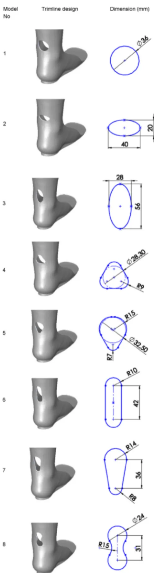
Fig. 3. (a) The AFO model with the trimline performed on the dorsal part having circle geometry (b) Concept designs of the dorsal trimlines with eight alternative geometries. Model 1: circle, Model 2: horizontal ellipse, Model 3: vertical ellipse, Model 4: rounded triangle, Model 5: rounded inverse triangle, Model 6: slot, Model 7 and Model 8: slot variations.
2.2. Experimental bending text on the AFO
In our study, to determine the peak lateral external force that the AFO can be exposed to without causing large deflections, we
large rotational deformations to the AFO was found 34 N (17 N from the medial superior and lateral superior to the ankle each) (Fig. 2). This force value was taken into account as the loading con-dition for all FE AFO models with alternative trimline designs.
2.3. Alternative dorsal trimmed AFO models
In our previous study[15], we observed that the magnitude of the peak stress values over AFO was decreased by approximately 50% by moving the trimline from the medial and lateral parts to the dorsal region of the AFO. In that study, the trimline performed on the dorsal part had a circular geometry with a diameter of 36 mm (Fig. 3(a)). By taking these findings into account, we inves-tigated how the stress values would change with the alternative dorsal trimlines having different geometries and whether it would be possible to further reduce the peak stresses in this study.
Deep and sharp-edged trimline geometries would cause high stresses. On the other hand, the trimlines with curvilinear-edged and rounded angular geometries would enable homogeneous stress distribution. Besides, stress concentrations that occur due to aggressive trimlines can be reduced with wider trimlines
[10,20]. Therefore, in this study, eight alternative fundamental geometries with round corners (namely circle, horizontal ellipse, vertical ellipse, rounded triangle, rounded inverse triangle, slot and its variations) were determined as concept models of trimlines (Fig. 3(b)). The defined geometries could be trimmed practically using conventional manufacturing methods.
Fig. 4. Dorsal trimline designs with eight alternative geometries determined according to a reference displacement value (9.05 mm).
Trimming was performed in the ankle region so that the AFOs can be compatible with the flexion/extension motions of the ankle
joint. The centers of all trimlines geometries were determined con-centrically in the dorsal part of the AFO model (Fig. 3(b)). Fig. 6. Finite element von Mises stress analysis performed under the same boundary, loading, and displacement conditions. (a) Model 1 (b) Model 2 (c) Model 3 (d) Model 4 (e) Model 5 (f) Model 6 (g) Model 7 (h) Model 8.
while external loads and displacements were the same for all alter-native designs.
FE analysis of the AFO models was carried out in the Simulation module of the SolidWorks software (SolidWorks Corporation, Concord, MA, USA), where the trimline designs were constructed. Thus, possible computational errors and time consumption that may occur in the transfer of the AFO models to another FE analysis software were prevented.
The polypropylene copolymer was assigned to the AFO model from the material library of Solidworks as the material type and was defined as linear, isotropic, and elastic (Table 1).
The parabolic tetrahedral solid element was used to better define free form surfaces in the mesh network. Mesh structure and boundary conditions of Model 1 are shown inFig. 5. The model was fixed from its entire plantar surface. Two external forces (each 17 N) were applied from medial and lateral sides which are repre-senting the strap forces acting on the AFO. For the FE models cre-ated for all other models, the boundary and loading conditions were considered to be the same as in Model 1.
4. Results
The von Mises stress distributions obtained from the FE analysis of eight different trimline models are given inFig. 6. In the analysis, the maximum displacement (9.05 mm) of the models in the anteroposterior axis was kept constant.
The peak von Mises stress values obtained for all eight models are shown inTable 2. All values were below the yield strength limit (27.6 MPa). Model 1, Model 3, and Model 7 produced relatively lower stresses and among them, Model 3 generated the lowest peak stress value.
In the FE strain analysis, all elongation rates taken place over the AFO models were below the elongation at the yield point (16%). In Model 3, it was observed that the maximum strain did not occur on the trimmed edge, but on the medial edge of the
sal trimming and investigate the presence of a more efficient dorsal trimline, the stress–strain analysis was performed on eight differ-ent AFO models with differdiffer-ent geometrical features using the FE method. By keeping the loading, boundary, and displacement con-ditions applied to all models equal, the stress values of the models were compared. As a result of the FE analysis, relatively low-stress values were observed in the AFO models with trimline geometries of the circle (Model 1), vertical ellipse (Model 3), and two slot vari-ations (Model 7 and 8). The vertical elliptic trimline (Model 3) on the dorsal side of the AFO was the most effective to decrease the magnitude of the peak stress value. It is understood that during the bending of the vertical ellipse geometry with the applied load, the AFO distributes the stress concentrations along the edges of the ellipse and thus high stresses could be prevented. As for the strain analysis, we found all elongation rates below the yield point.
It was reported that peak stresses over AFOs occur around the lateral and medial segments of the ankle during gait[19,20]and microcracks and then material failures may take place in these seg-ments. Lautenschlager et al.[21]reported that using a larger radius trimline would reduce peak stresses but realized that this would also change the stiffness value of AFO and cause fatigue damage. However, using a webbing strap would provide resistance to ten-sion during plantar flexion, thereby preventing fatigue failure. Although this system is still used today, many other studies have been carried out to reduce the stresses occurring in AFOs to pre-vent plastic deformation[22,23]. These studies are generally based on the reinforcement of AFO with some structural additions. In our study, we examined the way of improving the structural strength of AFOs without using additional reinforcement structures by using a novel trimming approach. Reducing the peak stress values and distributing the stresses homogeneously would increase the structural strength of AFO without extra costs. Our study may pro-vide a complementary solution to orthotists in the fabrication more durable AFOs having homogeneously distributed stresses.
There are some limitations to our study. First, the mechanical properties of the AFO material were assumed linear, isotropic, and elastic, which would not precisely represent the mechanical behavior of the material. Second, the FE analysis was performed for the static case in which the probable fatigue behavior of the AFO material would not be observed[24]. And lastly, the defined loading and boundary conditions would not represent the actual biomechanical loading and boundary conditions that would be experienced during gait. Moreover, since the AFO dimensions are patient-specific, the eight trimline designs may result in different biomechanical effects for each patient. Therefore, it is necessary to experimentally observe the pros and cons of dorsal trimline design and evaluate the possible effects of the above-mentioned limitations in practice. More specifically, a randomized control study that analyzes the gait characteristics of spina bifida patients wearing custom-made AFOs trimmed at the dorsal side is Table 2
The peak von Mises stress values obtained for all eight models. Model
No
Maximum displacement along the anteroposterior axis (mm)
Maximum strain (%) Maximum von Mises Stress (MPa) 1 9.06 0.59 6.70 2 9.06 0.73 10.94 3 9.05 0.58 6.27 4 9.05 0.77 9.58 5 9.04 0.65 7.69 6 9.05 0.67 8.20 7 9.05 0.58 6.60 8 9.03 0.60 6.85
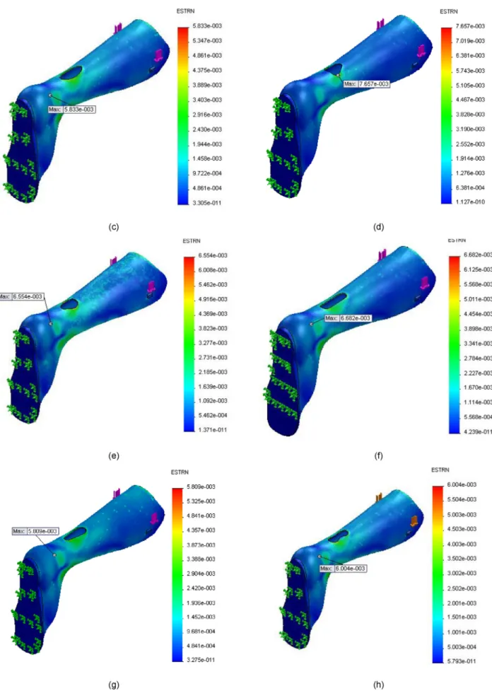
Fig. A1. Finite element strain analysis performed under same boundary, loading, and displacement conditions (a) Model 1 (b) Model 2 (c) Model 3 (d) Model 4 (e) Model 5 (f) Model 6 (g) Model 7 (h) Model 8.
could be developed for the trimming procedure so that the dorsal trimming process can be applied practically and accurately.
In conclusion, the vertical elliptic trimline on the dorsal side of the AFO is the best solution to decrease the peak stress values. The findings of our study are expected to contribute a complementary solution to orthotists in the fabrication of AFOs with high struc-tural strength. The next step will be the implementation of AFOs having different trimlines with the cooperation of the patients with spina bifida.
Declaration of Competing Interest
The authors declare that they have no known competing finan-cial interests or personal relationships that could have appeared to influence the work reported in this paper.
Appendix
The strain distributions under the same loading, boundary, and maximum displacement conditions obtained from finite element analysis for eight different trimline models are given in theFig. A1. References
[1] P.N. Hamdan, N.A. Hamzaid, J. Usman, M.A. Islam, V.S. Kean, K.A. Wahaba, et al., Variations of ankle-foot orthosis-constrained movements increase ankle range of movement while maintaining power output of recumbent cycling, Biomed. Eng.-Biomed. Tech. 63 (2018) 691–697, https://doi.org/10.1515/bmt-2017-0004.
[2] A. Ielapi, M. Forward, M. De Beule, Computational and experimental evaluation of the mechanical properties of ankle foot orthoses: a literature review, Prosthet. Orthot. Int. 43 (2019) 339–348, https://doi.org/10.1177/ 0309364618824452.
[3] H. Uustal, The orthotic prescription, in: J.D. Hsu, J. Michael, J. Fisk (Eds), AAOS Atlas of Orthoses and Assistive Devices. 4th ed. E-Book. Mosby; 2008:8-14. [4] H.K. Surmen, N.E. Akalan, Y.Z. Arslan, Design, Manufacture, and Selection of
Ankle-Foot-Orthoses. In: Encyclopedia of Information Science and Technology.
ankle-foot orthoses: effect of ankle trimline Part 2: orthosis characteristics and orthosis/patient matching, Prosthet. Orthot. Int. 20 (1996) 132–137,https:// doi.org/10.3109/03093649609164431.
[12]L. Aydin, S. Kucuk, A method for more accurate FEA results on a medical device developed by 3D technologies, Polym. Adv. Technol. 29 (2018) 2281–2286. [13] Y.S. Lee, Y.J. Choi, H.S. Kim, H.S. Lee, K.H. Cho, A study on the structural stress
analysis of plastic ankle foot orthosis (AFO) under dorsiflexion and plantarflextion conditions, Int. J. Mod Phys. B 20 (2006) 4559–4564,https:// doi.org/10.1142/s0217979206041689.
[14] R. Uning, N.A. Osman, R.A. Rahim, 3D finite element analysis of ankle-foot orthosis on patients with unilateral foot drop: a preliminary study. 4th Kuala Lumpur International Conference on Biomedical Engineering 2008;366-369. https://doi.org/10.1007/978-3-540-69139-6_93
[15] H.K. Surmen, N.E. Akalan, M.C. Fetvaci, Y.Z. Arslan, A novel dorsal trimline approach for passive-dynamic ankle-foot orthoses, Stroj. Vestn.-J. Mech. E 64 (2018) 185–194,https://doi.org/10.5545/sv-jme.2017.4987.
[16] Z. Liu, P. Zhang, M. Yan, X. Ren, Y. Xie, G. Huang, The application study of specific ankle-foot orthoses for stroke patients by 3D printing Somos NeXt, J. Biomater. Tiss. Eng. 9 (2019) 745–750,https://doi.org/10.1166/jbt.2019.2052. [17] A. Darwich, H. Nazha, A. Sliman, W. Abbas, Ankle-foot orthosis design between the tradition and the computerized perspectives, Int. J. Artif. Organs (2019) 1– 8,https://doi.org/10.1177/0391398819890348.
[18] T.M. Chu, R. Feng, Determination of stress distribution in various ankle-foot orthoses: experimental stress analysis, J. Prosthet. Orthot. 10 (1998) 11–16,
https://doi.org/10.1097/00008526-199801000-00005.
[19]T.M. Chu, N.P. Reddy, Stress distribution in the ankle-foot orthosis used to correct pathological gait, J. Rehabil. Res. Dev. 32 (1995) 349–360.
[20] T. Chu, Determination of peak stress on polypropylene ankle-foot orthoses due to weight change using strain gage technology, Exp. Tech. 24 (2000) 28–30,
https://doi.org/10.1111/j.1747-1567.2000.tb02268.x.
[21]E.P. Lautenschlager, S.C. Bayne, R. Wildes, J.C. Russ, M.J. Yanke, Materials investigation of failed plastic ankle-foot orthoses, Orthot. Prosthet. 29 (1975) 25–27.
[22]J. Munguia, K.W. Dalgarno, Ankle foot orthotics optimization by means of composite reinforcement of free-form structures, in: 4th International Solid Freeform Fabrication Symposium, 2013, pp. 766–776.
[23] G. Gomes, I. Lourenço, J. Oliveira, M. Gomes, A. Vale, L. Freire, et al., Structural reinforcements on AFO’s: a study using computer-aided design and finite element method. IEEE 5th Portuguese Meeting on Bioengineering 2017;77-80. Doi:10.1109/ENBENG.2017.7889432
[24]A. Peker, L. Aydin, S. Kucuk, G. Ozkoc, B. Cetinarslan, Z. Canturk, A. Selek, Additive manufacturing and biomechanical validation of a patient-specific diabetic insole, Polym. Adv. Technol. 31 (2020) 988–996.