A fast-switching light-writable and electric-erasable negative
photoelectrochromic cell based on Prussian blue films
Zhihui Jiao
a, Jun Ling Song
b, Xiao Wei Sun
a,c,n, Xue Wei Liu
b, Jin Min Wang
a, Lin Ke
d,
Hilmi Volkan Demir
a,b,eaSchool of Electrical and Electronic Engineering, Nanyang Technological University, Nanyang Avenue, Singapore 639798, Singapore bSchool of Physical and Mathematical Sciences, Nanyang Technological University, Nanyang Avenue, Singapore 637371, Singapore cDepartment of Applied Physics, College of Science, Tianjin University, Tianjin 300072, China
dInstitute of Material Research and Engineering, 3 Research Link, Singapore 117602, Singapore
eDepartment of Electrical and Electronics Engineering, Department of Physics, UNAM and National Institute of Materials Science and Nanotechnology, Bilkent University, Bilkent, Ankara 06800, Turkey
a r t i c l e i n f o
Article history: Received 25 July 2011 Accepted 21 October 2011 Keywords: Photoelectrochromic Prussian blue Nanocrystalline TiO2 Response timea b s t r a c t
We report a fast-switching negative photoelectrochromic cell composed of a dye-sensitized nanocrys-talline TiO2electrode and Prussian blue counter electrode sandwiching a LiI electrolyte. The cell can be bleached under illumination with shorted TiO2 and Prussian blue electrodes, and re-colored by applying an appropriate external voltage. The photo-bleaching and electric-coloring processes are fast and reversible. A maximum absorbance modulation of 0.44 recorded at 700 nm is obtained between bleached and colored states for the cell when the PB film’s thickness is 452 nm. Illuminated under different levels of light intensity or durations of time, the shorted cell shows adjustable optical absorption from 470 to 840 nm. The in-situ transmittance response depicts that the photo-bleaching response is 6.2 s for 70% transmittance change under 100 mW/cm2 illumination in short circuit configuration, and the re-coloration time is about 600 ms under 2 V bias recorded at 780 nm, with an electrochromic coloration efficiency of 103.4 cm2/C. The cell shows a good reversible stability and can be potentially applied in erasable displays.
&2011 Elsevier B.V. All rights reserved.
1. Introduction
In recent years, the growing interest in low-power systems has led to the development of various energy-efficient chromic technologies including electrochromism, photochromism, gaschromism,
thermal-chromism, and photoelectrochromism[1–16]. Among them,
photo-electrochromic devices have attracted significant attention because of their unique function of dynamically controlled solar energy gain and optical properties through switchable glazing in response to illumina-tion, with promising applications in smart windows, sunglasses and
light-writable low-information content displays [11,12,17,18].
Although various device configurations and working mechanisms
have been reported in recent years[11,19–21], most of the reported
photoelectrochromic devices are composed of a light-sensitive
photo-voltaic layer and an electrochromic layer. A dye-sensitized TiO2
nanoparticle (NP) photoanode has been most commonly adopted as the photovoltaic layer, and various electrochromic materials (inor-ganic or or(inor-ganic) have been assembled as the electrochromic
elec-trode including WO3or polyaniline[11,12,22,23]. Under illumination,
photoelectrons generated by the dye molecule inject into the
con-duction band of TiO2and then transport through the external circuit
to the counter electrochromic electrode, driving the ions in the electrolyte to intercalate into the electrochromic layer at the same time. Correspondingly, the transmittance of the photoelectrochromic device will be decreased as a result of the darkened electrochromic layer. The bleaching state can be achieved by either short circuit or open circuit configuration with light blocked. The switching response is mainly dependent on the electrochromic material and electrode adopted. Recently, Chen’s group improved the bleaching rate of a
WO3-based photoelectrochromic device using a patterned WO3/Pt
electrode, providing the charge transfer pathways to accelerate the
bleaching process[22]. Under illumination, the cell can be colored in
a short circuit configuration with tunable transmittance and bleached more quickly when the circuit is opened (!60 s).
Prussian blue [PB, iron (III) hexacyanoferrate (II)] is a well known synthetic coordination-compounded transition metal
Contents lists available atSciVerse ScienceDirect
journal homepage:www.elsevier.com/locate/solmat
Solar Energy Materials & Solar Cells
0927-0248/$ - see front matter & 2011 Elsevier B.V. All rights reserved. doi:10.1016/j.solmat.2011.10.030
n
Corresponding author at: School of Electrical and Electronic Engineering, Nanyang Technological University, Nanyang Avenue, Singapore 639798, Singapore. Tel.: þ65 67905369; fax: þ65 67933318.
E-mail address:
sensors [27], catalysts [28], and batteries [29]. Different from
WO3, PB is an anodically coloring electrochromic material with
promising electrochromic properties. It is reported that an elec-trodeposited PB film exhibits electrochromism between blue and
colorless state with a fast response (r100 ms) and a high
durability for 5 # 106 cycles [30]. The excellent electrochromic
performance makes it an ideal candidate for applications in smart windows and electronic paper displays. Although there have been numerous reports regarding electrochromic applications of PB, to our knowledge, such a PB film has not been incorporated in a device to enable fast-switching light-writable and electric-erasa-ble photoelectrochromic operation to date.
In this study, we propose and demonstrate a negative photo-electrochromic cell, composed of an electrodeposited PB
electro-chromic electrode and a dye-sensitized TiO2 NP photoanode.
The cell can be bleached in short circuit configuration under illumination and re-coloration can be achieved through applying a proper external voltage with fast switching response and good reversibility, providing a negative mode to the existing photo-electrochromic technology. The bleached cell can also be re-colored in either short circuit under dark state or open circuit under illumination with a slow speed. The photoelectrochromic cell shows obvious color change between colored and bleached state, promising for light-writable and electric-erasable informa-tion display applicainforma-tions.
2. Experimental details
2.1. Electrodeposition and characterization of PB films
Fluorine doped tin oxide (SnO2:F, FTO) glasses (NSG Group,
Rs¼14
O
/& and 2.2 mm thick) washed by acetone, isopropanol,and de-ionized water in sequence were used as substrates. The electrodeposition of PB films was carried out in a standard three-electrode system (VersaSTAT 3F Potentiostat/Galvanostat) with a clean FTO glass (2 cm # 3 cm) as the working electrode, a platinum sheet as the counter electrode, and a Ag/AgCl/sat’d KCl as the reference electrode. The electrodeposition bath of PB
contained 10 mM K3Fe(CN)6(Aldrich), 10 mM FeCl3 (Aldrich), and
0.1 M KCl (Aldrich). The PB films were prepared by applying a
constant cathodic current density of 50
m
A/cm2for 100, 300, 500and 700 s. Then the as-deposited blue PB films was rinsed by de-ionized water gently and dried at room temperature in atmosphere.
2.2. Preparation of dye-sensitized TiO2nanocrystalline photoanode
To fabricate the photoanode, TiO2 NP paint (Solaronix,
Ti-Nan-oxide T20/SP) was first screen-printed on a piece of FTO glass, which was ultrasonically cleaned sequentially by acetone, isopropanol, and de-ionized water. After calcination at 450 1C for 1 h, a transparent
and well adhesive TiO2 film with a thickness of !4
m
m wasobtained. Dye absorption was carried out by immersing the TiO2
electrode into a Z907 solution [(cis-bis(isothiocyanato)(2,20
-bipyr-idyl-4,40-dicarboxylato)(4,40-di-nonyl-20-bipyridyl)ruthenium(II)) in
dilute (8
m
M) ethanol solution containing 60 mM chenodeoxycholicacid] for 110 min. The electrode was then washed with acetonitrile for 3 times to remove the unanchored dye molecules. The dye coverage was kept low to make the cells semi-transparent in the ‘‘off’’ state.
2.3. Assembly of the photoelectrochromic cell
The dye-sensitized TiO2 nanocrystalline photoanode and PB
electrode were bonded together with hot-melt Surlyn spacers. Then a liquid electrolyte solution composed of 0.1 M LiI and
0.01 M 4-t-butylpyridine in
g
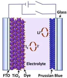
-butyrolactone was introducedbetween the two electrodes by capillary action. Finally the cell was sealed with epoxy. The final cell has a configuration of
FTO9TiO2ðdyeÞ9LiIþ4-t-butylpyridine9PB9FTO
which is also schematically shown inFig. 1.
2.4. Characterization
The morphologies of electrodeposited PB films were charac-terized by field emission scanning electron microscopy (FESEM JSM 6340F). Cyclic voltammogram (CV) of the PB film was
performed with 0.2 M LiClO4 in
g
-butyrolactone as theelectro-lyte, a platinum sheet as the counter electrode and Ag/AgCl/sat. KCl as the reference electrode. Thicknesses of the PB films were measured by a Tencor P-10 surface profiler. The transmittance was measured by a JASCO V670 UV–vis–NIR spectrophotometer. A 150 W Xe lamp with optical filter (4300 nm) was used as the light source and the light intensity was calibrated by a pyran-ometer (PMA 2144 from Solar Light)
3. Results and discussion
3.1. Characterization of electrodeposited PB films
The morphologies of electrodeposited PB films were
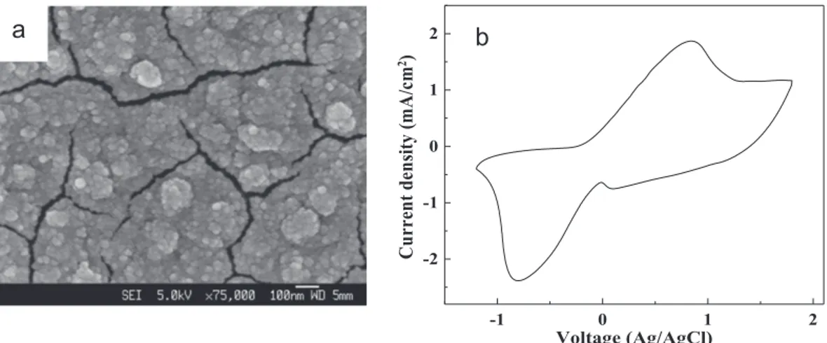
investi-gated (seeFig. 2a). It can be clearly seen fromFig. 2(a) that the
film is composed of accumulated nanoparticles with sizes of 20–50 nm. There are a lot of cracks with an average gap dimen-sion of !20 nm among the film, formed due to stress. The cyclic voltammetry (CV) curve of the PB film was measured with 0.2 M
LiClO4in
g
-butyrolactone as electrolyte at a scan rate of 100 mV/s(Fig. 2b). The broad oxidation and reduction peaks appear at 0.84
and '0.8 V, respectively, which are similar to those reported for Fig. 1. Schematic of the proposed hybrid photoelectrochromic cell.
electrodeposited PB films[30]. During the cycling, the color of the PB film was observed to change between blue and colorless. 3.2. Working principles of the photoelectrochromic cell
It is well known that PB is an anodically electrochromic
material, opposite to WO3, which is colored cathodically. Due to
the opposite electrochromic behaviors of PB and WO3, the
as-prepared cell is bleached rather than colored under illumination in short circuit configuration, providing a negative mode of the
existing photoelectrochromic technology[11,12]. Under
illumina-tion, light absorption by the sensitizing dye leads to electron
injection into the conduction band of TiO2 and then transport
through external circuit to the counter PB electrode, driving the
insertion of Liþ from the electrolyte into the PB film at the same
time. Accordingly, the color of the PB film changes from blue to colorless, which can be described by the following reaction:
FeðIIIÞ4½FeðIIÞðCNÞ6)3ðPB,blueÞþ4e'þ4Liþ
2Li4FeðIIÞ4½FeðIIÞðCNÞ6)3ðcolorlessÞ ð1Þ
At the same time, the excited dye molecules are reduced by iodide
ion (I') present in the electrolyte according to the reaction[31]:
2Sþþ3I'-2S0
þI'3 ð2Þ
where S0 and Sþ are the ground and ionized state of the dye
molecule, respectively. The photo-bleaching process terminates
when all I'in the electrolyte are transformed to triiodide (I'
3) or
until the generated photovoltage equals the electromotive force
of the formed Li4Fe(II)4[Fe(II)(CN)6]3 film, preventing the further
diffusion of the electrons into the EC layer.
Fig. 3(a) schematically depicts the photo-bleaching process of the
short circuit photoelectrochromic cell under illumination from the
side of dye-sensitized TiO2 NP photoanode. The color of PB film
changes from original blue to colorless, resulting from the insertion
of Liþ and electrons, while the iodide ions are oxidized to triiodide
by the excited dye molecules at the electrolyte\dye interface.
Fig. 3(b) shows the photograph of a bleached photoelectrochromic
cell (1.5 cm2) after illumination of 100 mW/cm2for 1 min in short
circuit configuration. The PB film assembled in the cell is electro-deposited for 300 s and its thickness is measured to be 452 nm. It can be seen that the original blue color of the PB film changes to colorless and the bleached cell displays pale yellow arising from the
dye molecules absorbing on the surface of TiO2 electrode. The
photovoltaic property of the cell was also investigated and shown
-1 0 1 2 -2 -1 0 1 2
C
ur
re
nt
d
en
sit
y
(m
A
/c
m
2)
Voltage (Ag/AgCl)Fig. 2. (a) SEM images of the electrodeposited PB film. (b) Cyclic voltammetry curve of PB film measured with 0.2 M LiClO4ing-butyrolactone as electrolyte at room temperature with a scan rate of 100 mV/s from '1.2 to1.7 V.
Fig. 3. Schematics and photographs of a photoelectrochromic cell with a 1.5 cm2 active area. The duration for electrodeposition of PB film is 300 s. (a) Schematic of the short circuit cell under illumination for bleaching. (b) Bleached cell achieved by illumination of 100 mW/cm2 for 1 min in short circuit configuration. (c) Schematic of the cell under external voltage for coloring. (d) Photograph of the cell at colored state after applying a 2 V bias at PB electrode for 30 s. (e, f) Spatially resolved bleaching states achieved by illuminating the cell with masks.
(
m
) is calculated to be 0.54.The re-coloration process was carried out by applying a positive
2 V bias on PB electrode (while TiO2 side is grounded) until the
current density was stabilized, during which Liþ was driven out
from PB film to the electrolyte, leaving PB in blue. At the same time, triiodide ions at the counter electrode were reduced to iodide ions by the electrons injected from the external bias:
I'
3þ2e'-3I' ð3Þ
In this way, triiodide ions are produced during the photo-bleaching process and are reduced back to iodide ions during the re-coloration process at the dye/electrolyte interface.
In fact, the re-coloration of the cell can also be achieved in either short circuit under dark or open circuit with or without
illumination. The charged Li4Fe(II)4[Fe(II)(CN)6]3 electrode
pos-sesses a negative potential, which causes the cell to discharge spontaneously back to its colored state. However, the re-colora-tion without external bias shows a much slower speed. It needs about !2 h to complete the re-coloration process of the open-circuited cell under illumination. The short-open-circuited cell shows a faster re-coloration speed than the open-circuited one, since the electrons can transport to the counter electrode through external circuit more efficiently, while the electrons in open circuit configuration are extracted from the EC layer and undergo a diffusion process to counter electrode. However, it still needs more than one hour for the re-coloration in short circuit config-uration. To reach a fast and efficient re-coloration, a proper external bias is adopted to overcome this problem.
To obtain good reversible stability, charges, and ions involved in the two processes should be balanced. Correspondingly, an optimum bias voltage should be adopted since a too large bias will lead to over oxidization of PB to Prussian White (PW), while a too small bias results in insufficient re-coloration and slow response. For our cells, 2 V bias was adopted for re-coloration and, as a result, a fast response and good stability were achieved.
Fig. 3(c) shows the schematic of the re-coloration process and
Fig. 3(d) depicts the photograph of the cell after applying a
positive 2 V bias on PB electrode for 30 s. It can be seen that the PB film changes to its original blue color reversibly after applying an electric stimuli. Moreover, spatially resolved bleaching was
achieved when the cell was partially illuminated (Fig. 3e and f).
The spatially resolved bleaching occurs because the electric field is created spatially in the illuminated region; i.e., the electric field is concentrated between the oxidized dye and reduced PB counter electrode. However, the resolution of such spatially resolved bleaching is limited as such the electric field is maintained by ion diffusions. The above results indicate the prepared photoelec-trochromic cells can be potentially applied in negative mode light-writable and electric-erasable information displays. 3.3. Optical-electro characterizations of the photoelectrochromic cell
It is clear that longer duration of electrodeposition will lead to thicker PB films with a deeper blue color. Since the bleached PB films remain highly transparent, for single PB electrochromic layer device, larger optical modulation (absorbance or transmittance) could be obtained using a thicker film. However, for thicker films, a larger operating voltage is needed for complete coloration/bleaching pro-cesses. To investigate the thickness effect on the optical modulation between bleached and colored states of the photoelectrochromic cells, PB films with electrodeposition durations of 100, 300, 500 and 700 s were assembled as electrochromic layers into the cells. The thicknesses of all the electrodeposited PB films were measured and
tabulated inTable 1. For all the cells, the conditions of dye-sensitized
TiO2nanocrystalline photoanode and electrolyte were fixed.
Subse-quently, all the cells were bleached by illumination at 100 mW/cm2
for 1 min in short circuit configuration and re-colored by a positive 2 V bias on the PB electrode for 30 s. Optical absorbance spectra were
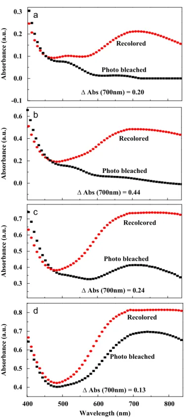
investigated for all cells at the two states (Fig. 4). It can be seen from
Fig. 4that with increased PB film thickness, the absorbance of all cells
at the colored state are enhanced from 470 to 840 nm. Also, the absorbance of all cells at the bleached state is obviously decreased compared to its colored state. Moreover, with PB film thickness increased from 123 to 452 nm, the absorbance modulations recorded at 700 nm between the two states are increased from 0.2 to 0.44. However, the modulation was decreased to 0.24 and 0.13 when the film thickness was further increased to 785 and 1106 nm, respec-tively, resulting from the insufficient bleaching. For our photoelec-trochromic cells, the photogenerated voltage (!0.4 V) is fixed under the same light intensity, and a too thick film will result in shallow bleaching level of PB film due to insufficient operating voltage and
increased resistance. As shown inFig. 4(b), the largest absorbance
modulation (0.44) recorded at 700 nm was obtained when the PB film thickness is set to 452 nm. The corresponding transmittance of
the cell under this optimum condition is shown in Fig. S2 for
reference. Compared with the colored states, the absorbance of all cells at the bleached states are increased in the spectral range of 400– 470 nm, which may be attributed to the absorption of triiodide ions formed at the dye\electrolyte interface. In the following part, we fix the thickness of PB film at the optimal value (452 nm). Following the
standard test method of ASTM D1003A[32,15], the haze numbers of
the cell at bleached state were investigated and shown inFig. S3. It
can be seen that the haze number increases with decreasing wavelength, which is due to the scattering losses caused by the
TiO2nanoparticle becomes increasingly pronounced[15]. The
lumi-nous transmittance (Tlum) of the bleached device recorded from 400
to 850 nm is calculated to be 42%, and the luminous transmittance
(Tlum) of the colored device is 18%, which corresponds to a contrast
ratio of 2.3. The ratio is smaller than that of the commercial
electrochromic devices, which is normally larger than 3:1[33,34].
More work is being done now to further decrease the thickness of the
TiO2 nanoparticle electrode to improve the contrast ratio between
bleached and colored state of the device.
To further investigate the impact of light intensity on its absorbance, the cell was illuminated with simulated solar
illumina-tion of 5, 10, 20, 30, 40, 50, and 100 mW/cm2, respectively for a fixed
duration (3 s) in short circuit configuration (Fig. 5a). It can be seen
that with increased light intensity, the absorbance decreases gradu-ally from 470 to 840 nm. Moreover, the absorbance decreases
significantly in 3 s between 10 and 50 mW/cm2, and from 50 to
100 mW/cm2, the decrease is comparatively less, indicating
adjus-table absorption of the cell under different levels of light intensity
(grayscale is obtainable). Fig. 5(b) shows the absorbance spectra
after 5, 10, 15, 20, 25, 30, and 60 s of illumination with a fixed
simulated solar intensity of 5 mW/cm2. It can be seen that the
absorbance decreases with prolonged illumination time from 470 to 840 nm, and the decrease is mostly completed in 25 s, after which the decrease is not obvious. For both cases, there is not much difference of absorbance below 470 nm, indicating the cell mainly regulates the absorbance in the visible range. Thus the absorbance of ing absorbance modulation at 700 nm.
Type Duration (s) Thickness (nm) Absorbance modulation
A 100 123 0.20
B 300 452 0.44
C 500 785 0.24
the cell in the visible light range can be adjusted with either light intensity or illumination time.
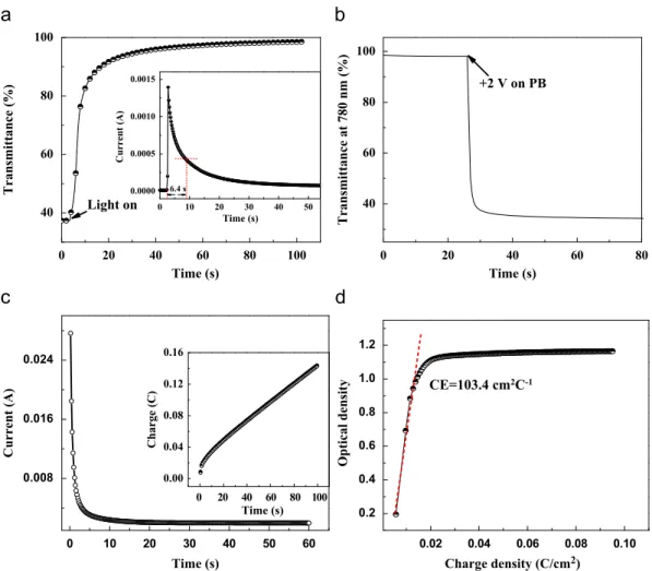
The photo-bleaching response of the cell was investigated at a
wavelength of 780 nm by 100 mW/cm2 illumination in short
circuit configuration (shown in Fig. 6a). The response for 70%
change is found to be 6.2 s. Inset ofFig. 6(a) depicts the
corre-sponding transient current change of the cell from the colored to
bleached state under illumination. It can be seen that a clear current impulse was obtained upon illumination. The current shoots up from near zero to 1.4 mA in 0.4 s, then decays quickly in several seconds before getting stabilized. The time for 70%
decrease (t70%) of the highest peak current is 6.4 s, very closed to
the response of transmittance change. Fig. 6(b) shows the
in-situ transmittance response recorded at 780 nm from the
bleached to colored state by applying a positive 2 V bias on PB electrode. The transmittance shows a fast decrease from 95% to
14% in less than one second. Fig. 6(c) shows the corresponding
transient current change of this process, displaying a fast current
decay. It can be seen that t70%of both the in-situ transmittance and
transient current are !600 ms, implying a fast electrochromic
coloration response. The inset of Fig. 6(c) shows the charge
involved during the coloration process by chronocoulometry. Corresponding to the current-time plot, charges are increased significantly in the first 10 s, and then a linear increase with time is found for the following process. The electrochromic performance of the photoelectrochromic cell was also investigated by measuring
its coloration efficiency (CE,
Z
) according toFig. 6(b and c). As it is-0.1
0.0
0.1
0.2
0.3
∆
Αbs (700nm) = 0.20
Photo bleached
Recolored
Absorbance (a.u.)
0.3
0.4
0.5
0.6
0.7
∆
Abs (700nm) = 0.24
∆
Abs (700nm) = 0.13
Photo bleached
Recolcored
400
0.4
0.5
0.6
0.7
0.8
Photo bleached
Recolored
Absorbance (a.u.)
Absorbance (a.u.)
Wavelength (nm)
0.0
0.2
0.4
0.6
∆
Abs (700nm) = 0.44
Photo bleached
Recolored
Absorbance (a.u.)
500
600
700
800
Fig. 4. Absorbance spectra of the phtotoelectrochromic cell at bleached state by illumination with a simulated solar intensity of 100 mW/cm2for 1 min and colored state by applying a 2 V bias at the PB electrode for 30 s. The PB films assembled in these cells were electrodeposited for (a) 100 s, (b) 300 s, (c) 500 s and (d) 700 s.
0.0 0.1 0.2 0.3 0.4 0.5 100 mW/cm2 50 mW/cm2 40 mW/cm2 30 mW/cm2 20 mW/cm2 10 mW/cm2 5 mW/cm2 Absorbance (a.u.) Wavelength (nm) As prepared 400 0.0 0.2 0.4 0.6 0.8 As prepared 5 s 10 s 15 s 20 s 25 s 30 s 60 s Absorbance (a.u.) Wavelength (nm) 500 600 700 800 400 500 600 700 800
Fig. 5. (a) Absorbance spectra of the as-prepared cell and illuminated with simulated light intensity levels of 5, 10, 20, 30, 40, 50, and 100 mW/cm2for 3 s in short circuit configuration. (b) Absorbance spectra of the as-prepared cell and illuminated with 5 mW/cm2for 5, 10, 15, 20, 25, 30, and 60 s.
known, CE represents the change in the optical density (
D
OD)per unit charge density change (
D
Q/A) during colorationor bleaching and can be calculated by Eqs. (4) and (5):
D
OD ¼ logðTbleachðl
Þ=Tcolorðl
ÞÞ ð4Þand
Z
¼D
OD=D
Q =A ð5Þwhere Tbleach(
l
) is the transmittance of the bleached state andTcolor(
l
) is the transmittance of the colored state.D
Qis the change of the charge consumed for the change in the optical density. TheCEof the photoelectrochromic cell recorded at 780 nm after adding
a 2 V bias voltage is shown inFig. 6(d). The CE was extracted as the
slope of the line fitted to the linear region of the curve. The
calculated CE value is 103.4 cm2/C for our cell, which is comparable
to the reported values[35].
The cell at colored state shows good stability in open circuit. While the photo-bleached cell gradually returns to colored state in either short circuit under dark state or open circuit with or without
illumination, since the charged Li4Fe(II)4[Fe(II)(CN)6]3electrode
pos-sesses a negative potential that causes the cell to discharge
sponta-neously back to its colored state. Fig.7 shows the transmittance
change of the cell in short circuit under dark and open circuit under illumination recorded at 780 nm. The cell was photo-bleached under
100 mW/cm2illumination in short circuit configuration for 100 s. It
can be seen that the transmittance gradually decrease in either short or open circuit. Moreover, the short-circuited cell shows a faster decrease rate than that of the open-circuited one. The time for 30%
transmittance decrease are found to be 806 s and 505 s for open-circuited and short-open-circuited case, respectively.
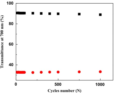
The stability of the photoelectrochromic cell was also investi-gated by measuring the transmittance changes recorded at
700 nm between the bleached and colored states (Fig. 8). The
0 20 40 60 80 100 40 60 80 100 0 10 20 30 40 50 0.0000 0.0005 0.0010 0.0015 Current (A) Time (s) 6.4 s Time (s) Transmittance (%) Light on 0 20 40 60 80 40 60 80 100 Time (s) Transmittance at 780 nm (%) +2 V on PB 0 10 20 30 40 50 60 0.008 0.016 0.024 0 20 40 60 80 100 0.00 0.04 0.08 0.12 0.16 Charge (C) Time (s) Current (A) Time (s) 0.02 0.04 0.06 0.08 0.10 0.2 0.4 0.6 0.8 1.0 1.2 Optical density Charge density (C/cm2) CE=103.4 cm2C-1
Fig. 6. (a) In-situ transmittance response of the cell under 100 mW/cm2 illumination in short circuit configuration at 780 nm. Inset: transient current changes. (b) Transmittance response at 780 nm under 2 V bias. (c) Corresponding current changes of the coloration process. Inset: integrated charge for coloration. (d) Coloration efficiency curve of the photoelectrochromic cell recorded at 780 nm with 2 V bias.
200
40
60
80
100
Light off
Open circuit
Short circuit
Transmittance (%)
Time (s)
Light on
400
600
800
1000
1200
Fig. 7. Optical transmittance change versus time of the photoelectrochromic cell in short circuit under dark and open circuit under illumination. The cell was bleached under 100 mW/cm2illumination in short circuit configuration for 100 s.
photo-bleaching process of the cell was conducted under
100 mW/cm2illumination in short circuit configuration for 60 s
and the re-coloration was obtained by adding a 2 V bias on PB electrode for 30 s. After 1000 cycles of operation, the performance of the cell is still quite stable. The transmittance attenuation was about 57.8% (from 90.6% to 32.8%) of the first cycle, and after 1000 cycles, it had decreased to ca. 55.7% (from 88.9% to 33.2%); only 2.1% optical degradation was found, indicating a good stability. 4. Conclusions
In conclusion, a fast-switching negative photoelectrochromic cell
composed of dye-sensitized nanocrystalline TiO2and PB electrodes
was studied. Adjustable grayscales were obtained by illuminating the cell with different light intensity and time. The photo bleaching
response of the cell at 100 mW/cm2is 6.2 s, and the electrochromic
response with a 2 V bias is about 600 ms for 70% transmittance change at 780 nm with electrochromic coloration efficiency of
103.4 cm2/C. This hybrid photoelectrochromic cell shows good
stabi-lity and can be potentially applied in erasable displays. Acknowledgments
The authors would like to thank the financial support from the Science and Engineering Research Council, Agency for Science,
Technology and Research (AnSTAR) of Singapore (Project nos. 092
101 0057 and 092 151 0088), Singapore NRF-RF-2009-09, and National Natural Science Foundation of China (NSFC) (Project nos. 61006037 and 61076015).
Appendix. Supplementary materials
Supplementary data associated with this article can be found
in the online version atdoi:10.1016/j.solmat.2011.10.030.
References
[1] C.M. Lampert, Electrochromic materials and devices for energy-efficient windows, Solar Energy Materials 11 (1984) 1–27.
[2] C.M. Lampert, Smart switchable glazing for solar energy and daylight control, Solar Energy Materials and Solar Cells 52 (1998) 207–221.
[3] C.M. Lampert, Electrochromics–history, technology, and the future, in: B.V.R. Chowdari, S.R.S. Prabaharan, M. Yahaya, I.A. Talib (Eds.), Proceed-ings of the Eighth Asian Conference on Solid State Ionics: Trends in the New Millennium, Langkawi, Malaysia, 2002, pp. 411–422.
[4] C.G. Granqvist, Oxide electrochromics: why, how, and whither, Solar Energy Materials and Solar Cells 92 (2008) 203–208.
[5] C.G. Granqvist, P.C. Lansaker, N.R. Mlyuka, G.A. Niklasson, E. Avendano, Progress in chromogenics: new results for electrochromic and thermochromic materials and devices, Solar Energy Materials and Solar Cells 93 (2009) 2032–2039. [6] C.G. Granqvist, Electrochromic materials: out of a niche, Nature Materials 5
(2006) 89–90.
[7] M. Sun, N. Xu, Y.W. Cao, J.N. Yao, E.G. Wang, Nanocrystalline tungsten oxide thin film: preparation, microstructure, and photochromic behavior, Journal of Materials Research 15 (2000) 927–933.
[8] U.O. Krasovec, B. Orel, A. Georg, V. Wittwer, The gasochromic properties of sol–gel WO3films with sputtered Pt catalyst, Solar Energy 68 (2000) 541–551. [9] D. Schweiger, A. Georg, W. Graf, V. Wittwer, Examination of the kinetics and
performance of a catalytically switching (gasochromic) device, Solar Energy Materials and Solar Cells 54 (1998) 99–108.
[10] V. Wittwer, M. Datz, I. Ell, A. Georg, W. Graf, G. Walze, Gasochromic windows, Solar Energy Materials and Solar Cells 84 (2004) 214–305.
[11] C. Bechinger, S. Ferrer, A. Zaban, J. Sprague, B.A. Gregg, Photoelectrochromic windows and displays, Nature 383 (1996) 608–610.
[12] B.A. Gregg, Photoelectrochromic cells and their applications, Endeavour 21 (1997) 52–55.
[13] H. Huang, L. Jiang, W.K. Zhang, Y.P. Gan, X.Y. Tao, H.F. Chen, Photoelec-trochromic properties and energy storage of TiO2 ' xNx/NiO bilayer thin films, Solar Energy Materials and Solar Cells 94 (2010) 355–359.
[14] H. Huang, S.X. Lu, W.K. Zhang, Y.P. Gan, C.T. Wang, L. Yu, X.Y. Tao, Photo-electrochromic properties of NiO film deposited on an N-doped TiO2 photo-catalytical layer, Journal of Physics and Chemistry of Solids 70 (2009) 745–749.
[15] G. Leftheriotis, G. Syrrokostas, P. Yianoulis, Development of photoelectro-chromic devices for dynamic solar control in buildings, Solar Energy Materials and Solar Cells 94 (2010) 2304–2313.
[16] G. De Filpo, S. Mormile, F.P. Nicoletta, G. Chidichimo, Fast, self-supplied, all-solid photoelectrochromic film, Journal of Power Sources 195 (2010) 4365–4369. [17] C.M. Lampert, Progress in switching windows, in: C.M. Lampert,
C.G. Granqvist, K.L. Lewis (Eds.), Proceedings of the Conference on Solar and Switching Materials, SPIE-International Society for Optical Engineering, Bellingham, 2001, pp. 95–103.
[18] J.Y. Liao, K.C.J. Ho, A photoelectrochromic device using a PEDOT thin film, Journal of New Materials for Electrochemical Systems 8 (2005) 37–47. [19] U.O. Krasovec, A. Georg, V. Wittwer, J. Luther, M. Topic, Performance of a solid
state photoelectrochromic device, Solar Energy Materials and Solar Cells 84 (2004) 369–380.
[20] Y. Ohko, T. Tatsuma, T. Fujii, K. Naoi, C. Niwa, Y. Kubota, A. Fujishima, Multicolour photochromism of TiO2films loaded with silver nanoparticles, Nature Materials 2 (2003) 29–31.
[21] T. Tatsuma, K. Suzuki, Photoelectrochromic cell with a Ag–TiO2 nanocompo-site: concepts of drawing and display modes, Electrochemistry Communica-tions 9 (2007) 574–576.
[22] J.J. Wu, M.D. Hsieh, W.P. Liao, W.T. Wu, J.S. Chen, Fast-switching photovolta-chromic cells with tunable transmittance, ACS Nano 3 (2009) 2297–2303. [23] X.F. Yu, Y.X. Li, N.F. Zhu, Q.B. Yang, K. Kalantar-zadeh, A polyaniline nanofibre
electrode and its application in a self-powered photoelectrochromic cell, Nanotechnology 18 (2007) 8.
[24] V.D. Neff, Electrochemical oxidation and reduction of thin-films of Prussian blue, Journal of the Electrochemical Society 125 (1978) 886–887. [25] D.M. DeLongchamp, P.T. Hammond, High-contrast electrochromism and
controllable dissolution of assembled Prussian blue/polymer nanocompo-sites, Advanced Functional Materials 14 (2004) 224–232.
[26] S. Hara, H. Tanaka, T. Kawamoto, M. Tokumoto, M. Yamada, A. Gotoh, H. Uchida, M Kurihara, M. Sakamoto, Electrochromic thin film of Prussian blue nanoparticles fabricated using wet process, Japanese Journal of Applied Physics 46 (Part 2) (2007) L945–L947.
[27] A.A. Karyakin, Prussian blue and its analogues: electrochemistry and analy-tical applications, Electroanalysis 13 (2001) 813–819.
[28] U. Scharf, E.W. Grabner, Electrocatalytic oxidation of hydrazine at a Prussian blue—modified glassy carbon electrode, Electrochimica Acta 41 (1996) 233–239. [29] A. Eftekhari, Potassium secondary cell based on Prussian blue cathode,
Journal of Power Sources 126 (2004) 221–228.
[30] K. Itaya, T. Ataka, S. Toshima, Spectroelectrochemistry and electrochemical preparation method of Prussian blue modified electrodes, Journal of the American Chemical Society 104 (1982) 4767–4772.
[31] B. Oregan, M. Gratzel, A low-cost, high-efficiency solar-cell based on dye-sensitized colloidal TiO2films, Nature 353 (1991) 737–740.
[32] H.L. Yu, C.C. Hsiao, W.C. Liu, New apparatus for haze measurement for transparent media, Measurement Science and Technology 17 (2006) N29–N36.
[33] SAGE Electrochromics INC.,/http://www.sage-ec.comS. [34] EControl-Glas Gmbh,/http://www.econtrol-glas.deS.
[35] L.C. Chen, Y.H. Huang, K.T. Hou, A complementary electrochromic system based on Prussian blue and indium hexacyanoferrate, Journal of the Solid State Electrochemistry 7 (2002) 6–10.
0
40
60
80
100
Transmittance at 700 nm (%)
Cycles number (N)
500
1000
Fig. 8. Transmittance change (DT) at 700 nm as a function of cycle number of the photoelectrochromic cell, bleached under 100 mW/cm2illumination for 60 s and colored by adding a 2 V bias for 30 s.