AN ANALYTICAL INVESTIGATION OF A BUILDING HAVING SOFT STOREY IRREGULARITY STRENGTHENED WITH CONCENTRICALLY STEEL BRACES
1Alptuğ ÜNAL
1Konya Technical University, Faculty of Engineering and Natural Sciences, Department of Civil Engineering, Konya, TURKEY
(Geliş/Received: 04.04.2019; Kabul/Accepted in Revised Form: 26.06.2019)
ABSTRACT: When buildings that were damaged and destroyed in major earthquakes in previous years
are examined, it is seen that these buildings have several structural defects. One of these defects is that soft storey irregularity is not predicted in reinforced concrete buildings. For this reason, many buildings collapsed because of the major earthquakes, resulting in loss of life and property. Buildings stocks in earthquake zones must be inspected and buildings with the soft storey irregularity must be strengthened immediately. Also, strengthening methods are required to be quick and effective, and aesthetics of structures should not be disturbed. In this study, a 10-storey building with the soft storey irregularity is discussed. The building is strengthened with five different types of Steel Braces in various earthquake regulations in the world. The strengthening was conducted with a nonlinear analysis program and results were evaluated. According to the results, it was found that the Concentrically Steel Braces significantly increased the stiffness of the reinforced concrete building and eliminated the soft storey irregularity.
Key Words: Soft Storey, Concentrically Steel Braces, strengthening, reinforced concrete building, earthquake.
Yumuşak Kat Düzensizliği Bulunan Bir Binanın Merkezi Çelik Çaprazlar ile Güçlendirilmesinin Analitik Olarak İncelenmesi
ÖZ: Son yıllarda meydana gelen büyük depremlerde hasar gören ve yıkılan binalar incelendiğinde bu
binaların çeşitli yapı kusurları olduğu görülmüştür. Bu kusurlardan bir tanesi de yumuşak kat düzensizliğinin betonarme binalarda öngörülmemiş olmasıdır. Bu sebeple birçok bina, büyük depremler sonucu yıkılmış ve can ve mal kaybı meydana gelmiştir. Deprem bölgelerindeki yapı stoğunun bir an önce incelenmesi ve yumuşak kat düzensizliği bulunan binaların bir an önce güçlendirilmesi gerekmektedir. Yapılacak olan güçlendirme yöntemlerinin hızlı ve etkili olmasının yanında yapının estetiğinin bozulmaması gerekmektedir. Yapılan bu çalışmada yumuşak kat düzensizliği bulunan 10 katlı bir bina ele alınmıştır. Bu bina Dünyadaki çeşitli deprem yönetmeliklerinde bulunan 5 farklı Merkezi Çelik Çapraz çeşidi ile güçlendirilmiştir. Güçlendirme işlemi bir non-lineer analiz programı ile yapılmış olup, sonuçlar değerlendirilmiştir. Elde edilen sonuçlara göre Merkezi Çelik Çaprazların betonarme binanın rijitliğini önemli ölçüde arttırdığı ve yumuşak kat düzensizliğini ortadan kaldırdığı görülmüştür.
INTRODUCTION
Because of major earthquakes that have occurred in recent years, many lives and property losses have taken place. It has been ascertained that most of damaged and destroyed buildings do not comply with norms stated in regulations. When building stocks in Turkey and in the world are examined, it is seen that the ground floors of many buildings are designed as workplaces. For this reason, no or very few walls were used on the ground floors of the buildings compared to the upper floors. It is, by implication, observed that the upper floors of the buildings designed in this way are very rigid compared to the ground floor, leading to the formation of the Soft Storey Irregularity (Figure 1).
Figure 1. Examples of short storey irregularity (Korkmaz and Ucar, 2006)
The formation of the “Soft Storey”, which is stated in the world’s prominent earthquake regulations, is usually caused by the decrease in the stiffness of the ground floors. Plastic transfigurations at the lower and upper ends of the columns lead to a dangerous lateral displacement mechanism along with a large amount of elastic transfrontier transfiguration at the column ends, and collapse is frequently inevitable (TEC2007, 2007; TEC2018, 2018).
Buildings with soft storey irregularity should be detected and strengthened against the earthquake immediately. There are many strengthening methods in the literature to prevent soft storey irregularity (Oinam and Sahoo, 2019; Thinley and Hao, 2017; Benavent-Climent and Mota-Paez, 2017; Shin et al., 2016; Sahoo and Rai, 2013). In these strengthening methods, however, the buildings must be completely evacuated. In addition, the aesthetics of the building deteriorate in the suggested strengthening methods. Therefore, it is necessary to propose strengthening methods without in need of evacuation of building and disturbing aesthetics.
Concentrically Steel Braces (CSB) are utilized in order to meet the lateral load in steel buildings in the earthquake regulations. Although CSBs are not usually used in reinforced concrete buildings, it is still utilized in some cases as strengthening elements (Ju et al., 2014; Lee, 2015; Mowrtage, 2013; Unal and Kaltakci, 2016; Varum et al., 2013; Ebadi et al., 2018; Javadi and Yamakawa, 2019; Liu et al., 2019; Mashhadiali and Kheyroddin, 2018; Mazza et al., 2018; Oinam and Sahoo, 2018).
In this study, a building of 10 floors, with Soft Storey irregularity is based as a reference. Five different CSB applications were applied to the ground floor of the building. Strengthening was carried out by a non-linear analysis program and the results were evaluated. In lights of the results, it was found out that the Concentrically Steel Braces substantially increased the stiffness of the reinforced concrete building and eliminated the soft storey irregularity.
In this study, CSBs were used to eliminate the soft storey irregularity of the reinforced concrete building. The use of CBSs as strengthening elements in reinforced concrete is not well investigated. However, the use of CSBs as a strengthening element is thought to have many advantages. In this study, CBSs are preferred due to their practical application together with lightweight, aesthetical properties.
Moreover, evacuation of building may not be obligatory compared to other conventional strengthening methods (Figure 2).
Figure 2. Steel brace applications (Yon and Sayın, 2011)
MATERIAL AND METHOD
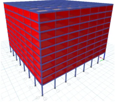
The aim in study is to strengthen a building with soft storey irregularity using CSB. For this purpose, a 10-storey reinforced concrete building was approached. The building was dealt with the help of a non-linear analysis program (ETABS17, 2018).The ground floor has no walls as it was designed as a workplace. In addition, in order to represent other available buildings, the ground floor height was considered as 5 m and the height of other floors was taken as 3 m. The building is symmetrical in X and Y directions and eight axes are designed to have seven openings. The distance between the axes of the building is designed 6 m intervals and the base-column joint area is defined as a fixed-support (Figure 3).
Figure 3. 3D view of the referenced building
The building is considered to be located in Central Düzce (Figure 4). For this reason, acceleration records were determined by selecting Central Düzce from the Disaster and Emergency Management
Centre (DEMC) Earthquake Zones Map (DEMC, 2019)
.
Assuming that the building is on a bad ground, it was chosen ZE ground class according to TEC2018. It is assumed that the building is used as a residence and the ground floor is a workplace. Based on the location of the building and the ground class, output from the DEMC (DEMC, 2019) official website is as follows (Table 1):Table 1. Outputs for earthquake ground motion levels
Definition DD2 DD3
SS: Short term map spectral acceleration coefficient 1.318 0.449
S1: Map spectral acceleration coefficient for 1.0-second period 0.358 0.121
SDS: Short term design spectral acceleration coefficient 1.150 0.827
SD1: Design spectral acceleration coefficient for 1.0-second period 0.919 0.485
PGA: Maximum ground acceleration [g] 0.542 0.193
PGV: Maximum ground speed [cm/sec] 34.410 12.041
TA: Lateral elastic design acceleration spectrum corner period (s) 0.160 0.117
TB: Lateral elastic design acceleration spectrum corner period (s) 0.799 0.587
TL: Period of transition to constant displacement zone in lateral elastic design
spectrum (s)
6.000 6.000 TAD: Vertical elastic design acceleration spectrum corner period (s) 0.053 0.039
TBD: Vertical elastic design acceleration spectrum corner period (s) 0.266 0.196
TLD: Period of transition to constant displacement zone in the vertical elastic
design spectrum (s)
3.000 3.000 * DD-3 (earthquake ground-motion level, probability of exceedance of which is 50% in 50 years), DD-2 (earthquake ground-motion level, probability of exceedance of which is 10% in 50 years)
Figure 4. Location of the building in question
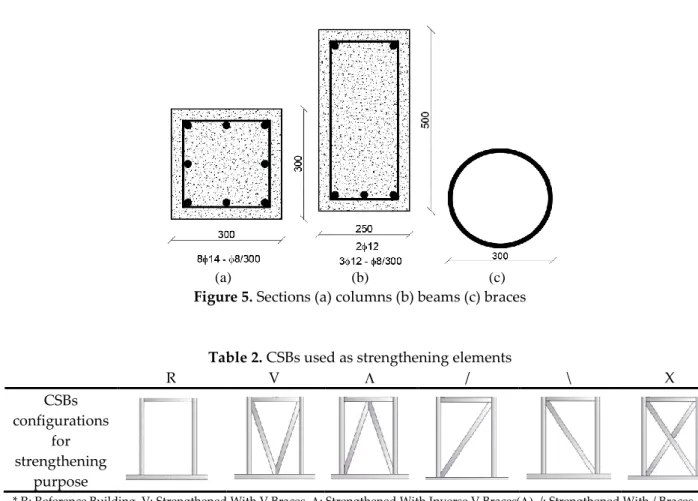
The columns are 30x30 cm and the beams are designed as 25x50 cm. 814 longitudinal reinforcement, 8/30 transverse reinforcement were used in the columns. In the beams, 312 tension reinforcement, 212 montage reinforcement and 8/30 transverse reinforcement were used. All slabs in the reinforced concrete building were formed with a thickness of 120 mm. In the CSBs used for strengthening, the outer diameter of the pipe section is 300 mm and the pipe thickness was chosen as 50 mm. The cross-sections of the reinforced concrete elements and the sections of the CSBs are shown in Figure 5. CSBs used as strengthening elements in reinforced concrete buildings are shown in Table 2 (TEC2007, 2007; TEC2018, 2018).
(a) (b) (c)
Figure 5. Sections (a) columns (b) beams (c) braces
Table 2. CSBs used as strengthening elements
R V / \ X CSBs configurations for strengthening purpose
* R: Reference Building, V: Strengthened With V Braces, : Strengthened With Inverse V Braces/: Strengthened With / Braces, \: Strengthened With Inverse / Braces (\), X: Strengthened With X Braces
Concrete class is C20 (fck = 20 MPa) in the reinforced concrete building and S420 (fy = 420 MPa, fu =
500 MPa) in reinforcement class. In the bracings used for strengthening, pipe profiles used in industry were taken as examples. Steel class of S355 (E = 210.000 MPa, fy = 355 MPa, fu = 510 MPa) were used in
CSBs. CSBs are designed as “Moment Transferring Braces” as stated in the regulations. Hence, since the connection points of the braces are intended to be fully interactive to the frame, no hinge definition is considered. Similarly, no hinge is defined in other reinforced concrete structural system elements.
The dead load on the floors in the reinforced concrete building was G = 1.5 kN / m2 and the live load
was taken as Q = 5 kN / m2. The weight of the walls on the beams was calculated as 15 kN/m, the
modulus of elasticity was E = 3600 MPa, the pressure strength was 8 MPa while the wall thickness was 200 mm.
The reinforced concrete building, having soft storey irregularity, was investigated by a non-linear analysis program (ETABS17, 2018). After defining material and section characteristics to the analysis program, building model was formed. Later, loads to affect the building were identified and these loads were put in the program. The referenced building and all the strengthened buildings were analyzed by three different methods and the differences between these methods were examined.
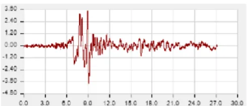
Equivalent Seismic Load Method (EL), Mode Superposition Method (MS) and Time History Analysis Method (TH) indicated in TEC2018 (TEC2018, 2018) were taken benefit for the buildings and the analysis was made accordingly. In general, the EL method is more common for designing low-rise structures while MS method is more widely used in all type of structures. In TH method, the acceleration records of the earthquake occurring in the area where the building is located are used. For EL and MS, Z4 local site class, building importance factor 1 and earthquake zone 1 were chosen. For TH analysis, as seen in Figure 6, Düzce earthquake acceleration records are used.
Figure 6. Düzce earthquake acceleration record
RESULTS AND DISCUSSION
In this study, a strengthening method is exhibited in the buildings with Soft Storey irregularity. For this, a non-linear analysis program has been used to evaluate the results by strengthening the referenced building.
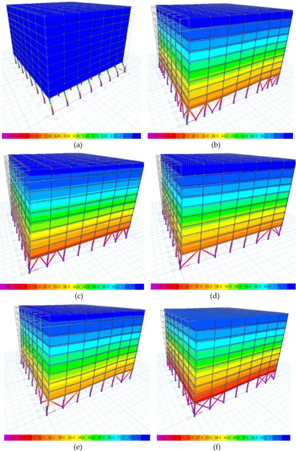
During examination of the result analyses, the stress conditions occurring in the building were examined. For this purpose, the stress levels obtained from the non-linear analysis program are given in Figure 7. As seen in Figure 7, because R building does not have strengthening elements, only the ground floor is damaged, indicating that the ground floor column ends will be hinged under a quake load and the collapse will be because of that. Such a collapse will be sudden and brittle. In buildings strengthened with CSB, the stress distribution did not occur only on the ground floor column ends, and the stress transmission was transferred to the entire building, which signalizes that Soft Storey irregularity was substantially prevented. It can be said that in buildings strengthened with CSB; V, and X buildings made a better stress transmission compared to the buildings / and \ buildings.
As buildings are strengthened, major increases occur in building weight, which also causes an increase in the earthquake load to be met by the building. Since CSBs are lighter than the materials used in other strengthening methods, the increase in earthquake load is not very high. For this purpose, base shear forces of the buildings were examined in Table 3. As can be seen from the table, base shear forces affecting the building increase with the same proportion as the weight of the building.
Table 3. Base shear forces
Building Type EL (kN) MS (kN) TH (kN) R 62.119 37.628 6.169 V 117.787 110.875 70.234 121.616 111.607 73.040 / 118.222 110.283 70.694 \ 110.285 105.137 63.661 X 127.201 113.090 77.924
In order to observe the increase of building stiffness after strengthening, natural vibration periods of the buildings should be determined. The natural vibration period of the building must be low in order to prevent soft storey irregularity. Table 4 shows the natural vibration periods of all buildings. As seen from the table, natural vibration periods have decreased by six times after the R building has been strengthened. The X building exhibits a more rigid behaviour than other strengthening methods do.
(a) (b)
(c) (d)
(e) (f)
Table 4. Natural vibration periods
R V / \ X
Natural Vibration Periods
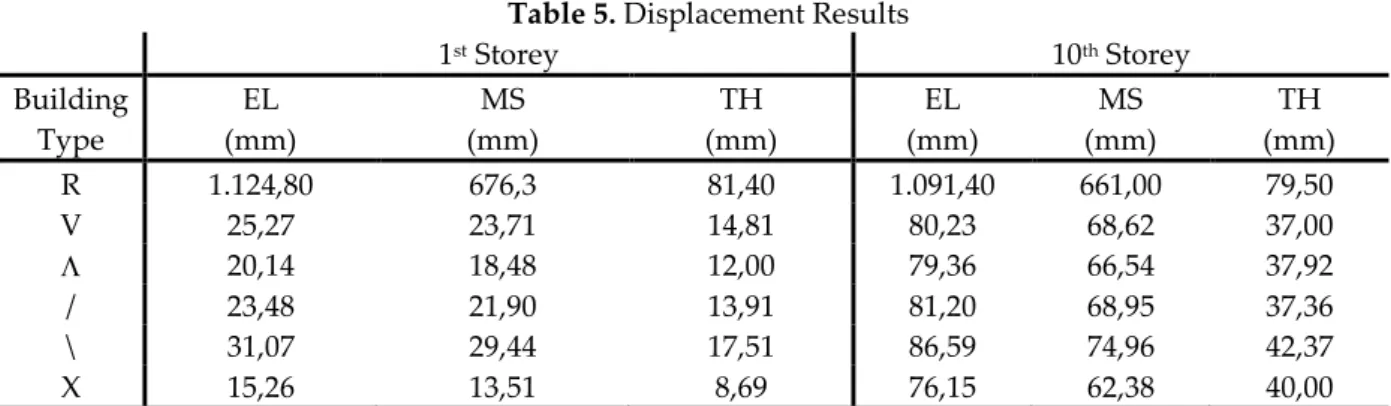
(sec) 10,552 1,682 1,616 1,674 1,826 1,528 In this study, since there is no strengthening in R building, and the first floor has over-displacement, the stresses in the building are concentrated on this floor, which will lead the collapse of the building. It is aimed to prevent this extreme displacement on the first floor with the proposed strengthening method. For that, the analysis results were examined and displacements on the 1st and 10th storeys were
determined for all buildings. Table 5 shows the displacements that occur for all loads on each storey of the buildings. As can be seen from the table, although the first storey in the building R has extreme displacement, the displacement on the first storey in other buildings is largely limited.
Table 5. Displacement Results
1st Storey 10th Storey Building Type EL (mm) MS (mm) TH (mm) EL (mm) MS (mm) TH (mm) R 1.124,80 676,3 81,40 1.091,40 661,00 79,50 V 25,27 23,71 14,81 80,23 68,62 37,00 20,14 18,48 12,00 79,36 66,54 37,92 / 23,48 21,90 13,91 81,20 68,95 37,36 \ 31,07 29,44 17,51 86,59 74,96 42,37 X 15,26 13,51 8,69 76,15 62,38 40,00
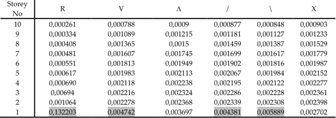
The major problem in buildings with soft storey irregularity is the “Relative Storey Drifts” between two storeys. “Relative Storey Drift Limitations” indicated in TEC2007 and TEC2018 must be applied to the whole building. For this reason, relative storey drifts are checked in the analysis. Relative storey drifts are examined in table 6 via EY method and MS method in table 7. Because TH displacements were very small, it was considered that a healthy evaluation could not be carried out and the relative storey drift control was not performed for the TH method. As it can be seen from Table 6 and Table 7, although there is a large relative drift on the first storey in the R building, the relative drift in the strengthened buildings has small values, which shows us that the suggested strengthening method is appropriate and usable.
In TEC2007, equation 1 was used to limit the relative drifts, but in TEC2018, equation 2 was introduced. In this study, two earthquake regulations were compared in terms of the relative storey drifts. coefficient in the equation 2 is the ratio of the elastic design spectral acceleration of the DD-3 earthquake ground motion to the elastic design spectral acceleration of DD-2 motion for the dominant vibration period in line with predicted earthquake. coefficient is considered as =1 in reinforced concrete buildings. In equation 2, coefficient was calculated as =1.8948. Depending on and values available in TEC2018, i,max/hi value must be lower than 0.00422. As for TEC2007, this value should be
smaller than 0,02. When Table 6 and Table 7 are examined, it appears that it cannot be possible to provide Relative Storey Drift limitation conditions in both two-earthquake regulations in R building. In all the buildings strengthened, although Relative Storey Drift limitations are provided in accordance with TEC2007, in TEC2018 only buildings strengthened with and X braces, limitations are realized, which reveals that TEC2018 is rather safer than TEC2007.
(Equation 2)Table 6. Relative storey drifts for EL method
Storey No R V / \ X 10 0,00071 0,001121 0,001255 0,001223 0,001186 0,001269 9 0,000882 0,001448 0,001591 0,001551 0,001492 0,001621 8 0,001036 0,00174 0,001892 0,001843 0,001767 0,001937 7 0,001168 0,001989 0,002149 0,002093 0,002004 0,002206 6 0,001277 0,002194 0,002358 0,002297 0,002199 0,002427 5 0,001359 0,00235 0,002518 0,002453 0,002352 0,002596 4 0,001432 0,002457 0,002626 0,002559 0,002458 0,002711 3 0,001372 0,002509 0,002678 0,00261 0,002516 0,002769 2 0,001898 0,00251 0,002672 0,002609 0,002532 0,002764 1 0,218287 0,005055 0,004029 0,004697 0,006214 0,003051
Table 7. Relative storey drifts for MS method
Storey No R V / \ X 10 0,000261 0,000788 0,0009 0,000877 0,000848 0,000903 9 0,000334 0,001089 0,001215 0,001181 0,001127 0,001233 8 0,000408 0,001365 0,0015 0,001459 0,001387 0,001529 7 0,000481 0,001607 0,001745 0,001699 0,001617 0,001779 6 0,000551 0,001813 0,001949 0,001902 0,001816 0,001987 5 0,000617 0,001983 0,002113 0,002067 0,001984 0,002152 4 0,000690 0,002118 0,002238 0,002195 0,002122 0,002277 3 0,00694 0,002216 0,002324 0,002286 0,002228 0,002361 2 0,001064 0,002278 0,002368 0,002339 0,002308 0,002398 1 0,132203 0,004742 0,003697 0,004381 0,005889 0,002702
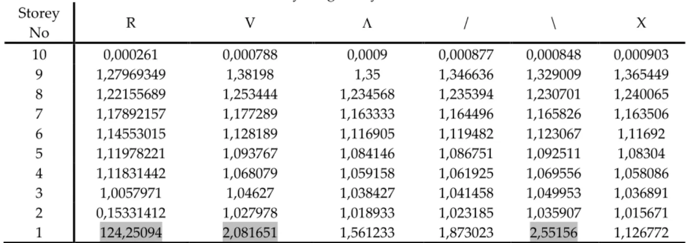
ki coefficient obtained through Equation 3 must be less than 2 in order not to have a soft storey
irregularity according to TEC2007 and TEC2018. For this reason, ki coefficients of EL and MS methods
are calculated and given in Table 8 and Table 9. As can be seen from the tables, , / and X braces avert soft storey formations. V brace is, on the other hand, is approximately the limit value.
Table 8. Soft storey irregularity control for EL method Storey No R V / \ X 10 0,00071 0,001121 0,001255 0,001223 0,001186 0,001269 9 1,24225352 1,291704 1,267729 1,268193 1,25801 1,277384 8 1,17460317 1,201657 1,189189 1,188266 1,184316 1,194941 7 1,12741313 1,143103 1,135835 1,135648 1,134126 1,138875 6 1,09332192 1,103067 1,097255 1,097468 1,097305 1,100181 5 1,064213 1,071103 1,067854 1,067915 1,069577 1,069633 4 1,05371597 1,045532 1,042891 1,043212 1,045068 1,044299 3 0,95810056 1,021164 1,019802 1,01993 1,023596 1,021394 2 1,38338192 1,000399 0,99776 0,999617 1,006359 0,998194 1 115,008957 2,013944 1,507859 1,800307 2,454186 1,103835
Table 9. Soft storey irregularity control for MS method
Storey No R V / \ X 10 0,000261 0,000788 0,0009 0,000877 0,000848 0,000903 9 1,27969349 1,38198 1,35 1,346636 1,329009 1,365449 8 1,22155689 1,253444 1,234568 1,235394 1,230701 1,240065 7 1,17892157 1,177289 1,163333 1,164496 1,165826 1,163506 6 1,14553015 1,128189 1,116905 1,119482 1,123067 1,11692 5 1,11978221 1,093767 1,084146 1,086751 1,092511 1,08304 4 1,11831442 1,068079 1,059158 1,061925 1,069556 1,058086 3 1,0057971 1,04627 1,038427 1,041458 1,049953 1,036891 2 0,15331412 1,027978 1,018933 1,023185 1,035907 1,015671 1 124,25094 2,081651 1,561233 1,873023 2,55156 1,126772
In the light of all these evaluations, it is seen that X braces are more effective than V braces although the same amount of material is used. Likewise, / braces are more effective than \ braces although the same amount of material is used.
When all these results are viewed, the idea that the buildings with soft storey irregularity can be strengthened with CSBs is formed. In CSBs, the most effective braces, offsetting the soft storey irregularity, are and X. Although other brace types are also effective, efficiency of and X braces is quite a lot compared to the others.
In this study, it was found that CSBs can be used for strengthening the buildings with soft storey irregularity. It is also possible to use CSBs as a strengthening element in cases where the lateral stiffness of buildings should be increased.
CONCLUSIONS
In this study, it is aimed to eliminate soft storey irregularity of a building by strengthening with CSBs. In this context, a 10-storey building with no walls on the ground floor but has walls on the upper floors has been discussed. In order to strengthen the building, it has been strengthened by using a computer program, which makes non-linear solution by using CSBs in different configurations on the ground floor. Analysis results were examined and conclusions were interpreted.
The natural vibration periods of the strengthened buildings are considerably lower than the non-strengthened building, which accordingly means that the non-strengthened buildings are more rigid and has fewer displacements. Similarly, when the displacements and relative storey drifts on the storeys were examined, it was seen that there was an excessive displacement on the ground storey in the
non-strengthened building. This was prevented in the building non-strengthened with CSB. Examining relative storey drifts, it was concluded that TEC2018 is quite safe compared to TEC2007. After viewing analysis results of the strengthened buildings, it was seen that X and braces were more effective than V, / and \. This strengthening method does not require complete evacuation of the building. Additionally, the method will not cause economic losses, as it is a fast strengthening method. In the light of all these evaluations, it was revealed that a building could be strengthened by using CSBs in buildings with Soft Storey irregularity.
REFERENCES