e-ISSN: 2618-575X
Available online at www.dergipark.gov.tr
INTERNATIONAL ADVANCED RESEARCHES
and
ENGINEERING JOURNAL
Journal homepage: www.dergipark.gov.tr/iarejInternational Open Access Volume 04 Issue 02 August,2020
* Corresponding author. Tel.: +90-338-226-2000 (5155) Fax: +90-338-226-2214
E-mail addresses: [email protected] (M. Yerlikaya), [email protected] (S. S. Gültekin), [email protected] (D. Uzer) ORCID: 0000-0001-8018-840X (M. Yerlikaya), 0000-0002-6287-9124 (S.S. Gültekin), 0000-0003-3850-3810 (D. Uzer) DOI: 10.35860/iarej.688973
Research Article
A novel design of a compact wideband patch antenna for sub-6 GHz
fifth-generation mobile systems
Mehmet Yerlikaya
a,*
, Seyfettin Sinan Gültekin
band Dilek Uzer
baKaramanoğlu Mehmetbey University, Department of Electrical and Electronics Engineering, Karaman, Turkey bKonya Technical University, Department of Electrical and Electronics Engineering, Konya, Turkey
ARTICLEINFO ABSTRACT
Article history:
Received 13 February 2020 Revised 20 May 2020 Accepted 02 June 2020
In this paper, a new broadband patch antenna design for fifth-generation (5G) sub-6 GHz mobile systems is presented. The proposed 5G antenna has a very compact size with an overall dimension of 10.7 × 22.5 mm2. The 5G antenna consists of a log-periodic patch in the form of an equilateral triangle with a 50 Ω microstrip line feed and a ground plane of rectangular shape. The prototype of the proposed 5G antenna was made by etching on an FR4 substrate with a 1.6mm thickness, 4.3 dielectric constant and 0.02 tangent loss. The 5G antenna is designed and simulated for the frequency band range of 3.4-4.2 GHz. According to the measurement results, the 5G antenna impedance band range is determined as 3.1-3.9 GHz. Besides, the proposed 5G antenna has also near-omnidirectional radiation patterns both simulation and measurement at the resonance frequencies of 3.8 GHz and 3.5 GHz, respectively. According to these results, the proposed antenna is showed similar radiation characteristics in both measured and simulated results. With all these radiation and physical properties, the proposed log-periodic patch antenna is very suitable for sub-6 GHz 5G mobile applications.
© 2020, Advanced Researches and Engineering Journal (IAREJ) and the Author(s).
Keywords: Log-periodic array Patch antenna Sub-6 GHz 5G antenna 1. Introduction
Fifth-generation (5G) is a new mobile broadband technology that is in its early stages and is planned to be widely used after 2020. Mobile communication systems, which became widespread after the 2000s, are evolved quite rapidly with different technologies over the last three decades from the analog transmission-based first generation (1G) to Internet Protocol (IP) based fourth-generation (4G) technologies. LTE-A (Long Term Evolution - Advanced) is an insufficient technology against the increasing demand for data, owing to smart devices are also defined as mobile users on the Internet of Things (IoT). Increasing demands for high data rates, low connection latency, low cost, low energy usage, and support for more users paved the way for the emergence of the fifth-generation (5G) technology. After the 5G, which is called next-generation technology, it is planned to overcome shortcomings of 4.5G and replace it in the near future. [1].
5G technology aims to meet the requirements of high data rates, faster connections and much more versatility than existing wireless networks. The most important expectation for the commercialization of 5G technology is the determination of all required standards, especially frequency spectrum sharing. Today, cellular communication is widely used in the sub-6 GHz band, especially at frequencies below the 3 GHz spectrum. The frequency spectrum of 5G systems is defined in two ranges as sub-6 GHz and above-6 GHz in terms of physical properties [2]. The International Telecommunication Union (ITU) adopted the IMT-2020 (International Mobile Telecommunication-2020) standards at the meeting held in Geneva in 2015. These standards contain the requirements for 5G networks, devices and services and are published as a report. According to this report; the frequency bands of 3.4 GHz to 3.6 GHz, 5 GHz to 6 GHz, 24.25 GHz to 27.5 GHz, 37 GHz to 40.5 GHz and 66-76 GHz are allocated for 5G communication [3]. After this development, the
frequency band between 3.4 GHz to 3.6 GHz is shared with mobile services in almost all countries and the availability of this spectrum for IMT is increasing worldwide. 3.4-3.8 GHz frequencies, which is the combination of LTE 42 and LTE 43 bands, is a band that is common to almost all countries, and this frequency band has significant potential for 5G researchers. International regulatory associations defined the different parts of 3.3-4.2 GHz spectrum for 5G sub-6 GHz as given in Figure 1.
Figure 1. Worldwide availability and planning of the 3.3-4.2 GHz frequency ranges [4]
As in all wireless communication systems, one of the most important elements of 5G mobile technologies is the antenna design appropriate to the system. Lots of antenna researchers focus on this topic and several sub-6 GHz 5G antennas are also proposed [5-7].
A hybrid MIMO antenna system with multiple antennas is presented by Ban et al. [5]. The proposed hybrid MIMO antenna system consists of two separate antenna modules for LTE and 5G. The LTE module has a two-element MIMO antenna system that can cover GSM, UMTS and LTE operations. n the 5G module, there is an eight-element MIMO array working with 3.5 GHz band that can cover 3400-3600 MHz frequencies. The proposed hybrid MIMO antenna has a 140 mm × 70 mm overall size and prototyped on an FR4 substrate with 0.8 mm thickness while each MIMO element has a 16 mm × 3 mm dimensions.
Parchin et al. [6] also proposed a MIMO antenna consisting of four elements for 5G mobile terminals. Each antenna element consists of a double-fed square ring slot resonator and its dimensions are 30 mm × 30 mm × 1.6 mm. The proposed MIMO antenna system has an overall dimension of 75 × 150 mm2 and is etched on an FR4 substrate with 4.4 relative permittivity. The proposed 5G MIMO antenna system has a dual-polarized 3.4-3.8 GHz frequency bandwidth.
Chattha [7] reported a two-element Planar Inverted-F Antenna (PIFA) antenna system that each element is fed by dual-port. Both PIFA elements are the same and each identical element consists of a radiating plate with 16 mm × 33 mm; while the PIFA antenna has a ground plane with
50 mm × 100 mm overall size. Also, an FR4 substrate with 4.4 relative permittivity and the thickness of 1.5 mm was used in the prototype of the proposed PIFA antenna.
Patch antennas, also called planar or microstrip antennas, are the most common types of antennas used in mobile systems because of their small size and ease of manufacture. Today's mobile communication systems, low profile broadband antennas are needed for high mobility and high-speed data transmission. However, a narrow bandwidth is one of the main shortcomings of traditional patch antennas. In the literature, different methods such as slots [8], defective ground structures (DGS) [9] and log-periodic arrays [10-12] have been tried to solve the narrow bandwidth problem of patch antennas.
In this paper, a compact wideband patch antenna for 5G mobile communication systems is presented. The 5G antenna geometry consists of a rectangular shaped ground plane and an equilateral triangle-shaped log-periodic patch array fed by a microstrip line. The dielectric constant of the FR4 substrate, 4.3, is used as the relative permittivity in the design of the proposed antenna, and its total size is 10.7×22.5×1.6 mm3. In this study, the antenna design and simulations has been carried out by using the Method of Moments (MoM) based IE3D package program [13]. The log-periodic array patch antenna has also been prototyped by printed circuit board (PCB) technology.
2. Antenna Geometry
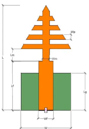
The detailed two-dimensional (2D) geometry of the proposed 5G patch antenna is given in Figure 2 and the dimensions of the antenna are given in Table 1. The proposed 5G antenna composed of a microstrip-fed log-periodic patch on the top and a dielectric substrate with a rectangular ground plane on the bottom. FR4 material with 1.6 mm thickness, 4.3 relative permeability and 0.02 loss tangency was used as the dielectric substrate of the antenna.
The proposed antenna has an overall size of 10.7×22.5 mm2 while the antenna patch consists of a log-periodic array with a small in size of 9.3×10.7 mm2. The log-periodic patch of the proposed 5G antenna is fed by a microstrip line of 3.1 mm width and 10.5 mm length. In addition, a strip line with a dimension of 1.55×2.7 mm2 is added between the microstrip line and the log-periodic patch to increase the impedance matching. The antenna ground plane consists of a rectangular-shaped structure with a size of 10.7 × 8 mm2.
2.1 Log-Periodic Patch Designing Process
The antenna patch proposed in this study is based on an equilateral triangle-sized periodic array using log-periodic array design methods [14-15]. To calculate the length of the longest element (Lmax) of the log-periodic array, Equation (1) is used:
Yerlikaya et al., International Advanced Researches and Engineering Journal 04(02): 129-133, 2020 131
Figure 2. The detailed 2D geometry of the log-periodic patch 5G antenna
Table 1. Dimensions of thethe log-periodic patch 5G antenna
Dimensions Explanation Size (mm)
W Total width of the antenna 10.7
L Total length of the antenna 22.5
Wf Width of microstrip line 3.1
Lf Length of microstrip line 10.5
Lg Length of ground plane 8.0
Wm Width of matching stripline 1.55
Lm Length of matching stripline 2.7
Wp Length of each log elements 1.0
max min 4 r c L f = (1)
where c is the speed of light in vacuum, εr is the relative permittivity of a dielectric substrate and fmin is the minimum frequency of the antenna operating band. In this study, the operating band is determined as a 3.4-4.2 GHz range to cover whole frequencies for sub-6 GHz 5G applications [4]. Thus, fmin is given as 3.4 GHz. Also, since FR4 material is used as the dielectric substrate, the value of 4.3 is determined as the relative permeability.
Another parameter that needs to be determined in the log-periodic array design is the number of array elements. The total number of elements (N) for the log-periodic array can be calculated by Equation (2):
1 log( ) log(1/ ) ar B B N
= + (2)where B is the bandwidth ratio, Bar is the active region bandwidth and τ is scaling factor. The scaling factor (τ) is given as 0.87 and the bandwidth ratio and active region
bandwidth parameters are determined from Equations (3-4), respectively: max min f B f = (3) 2 1.1 7.7(1 ) cot ar B = + − (4)
where α is the half-angle of the antenna. Since the proposed antenna has an equilateral triangle sized patch, 30 ° is used as the half-angle of the antenna.
By using Equations (3) and (4), B and Bar are calculated as 1.235 and 1.325, respectively. According to Equations 3 and 4, N is calculated as 5 from Equation (2). By using Equation (1), the length of the longest element is determined as 10.7 mm.
Finally, the antenna microstrip feed line length of Lf and microstrip feed line width of Wf are given as 10.5 mm and 3.1 mm using the calculation tool of the IE3D package program.
3. Results and Discussions
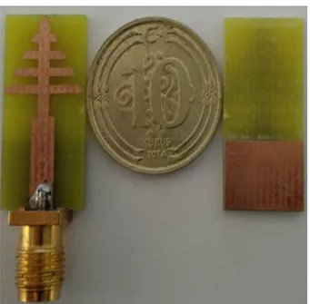
The proposed log-periodic patch antenna for sub-6 GHz 5G mobile applications is also printed on a double-sided FR4 dielectric substrate with a thickness of 1.6 mm and 4.3 relative permittivity. The photograph of the prototyped antenna is shown in Figure 3.
Firstly, the impedance bandwidth was determined for the analysis of the proposed log-periodic antenna. To determining the bandwidth, return loss graph was examined from the IE3D package program. Then, the antenna return loss measurement was made between the frequency range of 2 GHz to 5 GHz and verified with the simulated results. In this study, Keysight PNA 5224A vector network analyzer was used in all measurements. The simulated and measured S11 results are given comparatively in Figure 4. From the Figure 4, the -10 dB bandwidth is obtained as 3.4-4.2 GHz from the simulations, while the range for measurement results is determined as 3.1-3.9 GHz. Although there are some differences between the graphs, both measurement and simulation results are suitable for the frequency bands of sub-6 GHz 5G mobile systems [4].
After determining the antenna bandwidth, radiation pattern measurement and simulation studies were carried out. The 2D radiation pattern of the proposed 5G antenna for the E-plane (ϕ = 0 ° or xz-plane) and H-plane (ϕ = 90 ° or yz-plane) at 3.5 GHz frequency is shown in Figure 5a. In addition, the simulated three-dimensional (3D) radiation pattern of the log-periodic patch antenna at 3.5 GHz is also given in Figure 5b. From Figure 5a, maximum gains are 1.92 dBi and 1.9 dBi for E-plane and H plane, respectively. As can be seen from the 3D radiation pattern, it is understood that the maximum gains are in the E and H planes. As seen in Figure 5, the proposed 5G antenna has a near-omnidirectional radiation pattern at resonant frequency of 3.5 GHz.
Figure 3. Photograph of the prototyped the log-periodic patch 5G antenna
Figure 4. Measured and simulated S11 graph of the log-periodic patch 5G antenna
Thirdly, simulated maksimum gain and total efficiency values of the proposed 5G patch antenna are obtained. The compared maximum gain and total efficiency graphs of the 5G antenna are presented in Figure 6. As can be seen from the figure, the gain and efficiency curves are similar as it is expected. The maximum gain value for the antenna is 2.3 dBi at 3.8 GHz. Likewise, the total efficiency of the proposed antenna is 73% at 3.8 GHz.
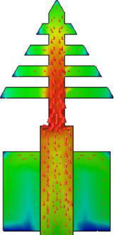
Finally, the proposed 5G antenna simulated surface current distributions at 3.5 GHz is given in Figure 7. According to current distributions in Figure 7, the majority of the radiation concentrated on the antenna patch and matching line.
According to these results, the proposed antenna stands out especially in terms of its small size and wide bandwidth compared to the antennas in the literature [5-7].
(a)
(b)
Figure 5. Radiation patterns of the log-periodic patch 5G antenna at 3.5 GHz: (a) 2D radiation pattern on E and H planes,
(b) 3D radiation pattern
Figure 6. The maximum gain and total efficiency graph of the log-periodic patch 5G antenna
Yerlikaya et al., International Advanced Researches and Engineering Journal 04(02): 129-133, 2020
Figure 7. The simulated surface current distributions of the log-periodic patch 5G antenna at 3.5 GHz
4. Conclusion
In this study, a novel wideband patch antenna with the log-periodic array is presented for sub-6 GHz 5G mobile systems. The proposed patch antenna has a very compact structure with total size of 10.7 × 22.5 mm2. The proposed 5G patch antenna is designed and manufactured on a double-sided FR4 substrate which has a relative permittivity of 4.3, a tangent loss of 0.02 and a thickness of 1.6 mm. The proposed antenna has a frequency bandwidth of 3.4-4.2 GHz by simulations, while this operating band is measured in the range 3.1-3.9 GHz. Besides, the antenna has a near-omnidirectional radiation pattern and a maximum gain value of 2.3 dBi.
Declaration
The author(s) declared no potential conflicts of interest with respect to the research, authorship, and/or publication of this article. The author(s) also declared that this article is original, was prepared in accordance with international publication and research ethics, and ethical committee permission or any special permission is not required.
References
1. Rappaport, T.S., Sun, S., Mayzus, R., Zhao, H., Azar, Y., Wang, K., Wong, G.N., Schulz, J.K., Samimi, M., and Gutierrez Jr, F.; Millimeter wave mobile communications
for 5G cellular: it will work!. IEEE Access, 2013. 1 (1): p.
335-349.
2. Lee, J., Tejedor, E., Ranta-aho, K., Wang, H., Lee, K.-T., Semaan, E., Mohyeldin, E., Song, J., Bergljung, C., and Jung, S.; Spectrum for 5G: global status, challenges, and
enabling technologies. IEEE Communications Magazine,
2018. 56 (3): p. 12-18.
3. Marcus, M. J.; 5G and IMT for 2020 and beyond [spectrum
policy and regulatory issues. IEEE Wireless Communications, 2015. 22(4): pp. 2-3.
4. Huawei Technologies Co. Ltd.; 5G Spectrum Public Policy
Position, 2017.
5. Ban, Y. L., Li, C., Wu, G. and Wong, K. L.; 4G/5G multiple
antennas for future multi-mode smartphone applications.
IEEE Access, 2016. 4: p. 2981–2988.
6. Parchin, N. O., Al-Yasir, Y. I. A., Ali, A. H., Elfergani, I., Noras, J. M., Rodriguez, J., and Abd-Alhameed, R.A.;
Eight-element dual-polarized MIMO slot antenna system for 5G smartphone applications. IEEE Access, 2019. 7: p.
15612-15622.
7. Chattha, H.T.; 4-Port 2-Element MIMO antenna for 5G
portable applications. IEEE Access, 2019. 7:
p.96516-96520.
8. Ambresh, P.A., Hadalgi, P.M. and Hunagund, P.V.; Planar
microstrip slot antenna for S & C band wireless applications. Journal of Physics: Conference Series, 2013.
435(1): p. 12-22.
9. Ansari, J.A., Verma, S., Verma, M.K. and Agrawal, N.; A
novel wide band microstrip-line-fed antenna with defected ground for CP operation. Progress In Electromagnetics
Research, 2015. 58: p.169-181.
10. Nasir, S.A., Arif, S., Mustaqim, M. and Khawaja, B.A.; A
log-periodic microstrip patch antenna design for dual band operation in next generation wireless LAN applications, in
IEEE 9th International Conference on Emerging technologies (ICET2013): Islamabad. p. 1-5.
11. Amini, A. and Oraizi, H.; Miniaturized UWB log-periodic
square fractal antenna. IEEE Antennas and Wireless
Propagation Letters, 2015. 14: p.1322-1325.
12. Yerlikaya, M., Gültekin, S.S. and Uzer, D., A Low Profile
Wideband Log Periodic Microstrip Antenna Design for C-Band Applications. Advanced Electromagnetics, 2019.
8(2): p.48-52.
13. Mentor Graphics, IE3DTM Version 15. HyperLynx®3D EM, 2015, Wilsonville.
14. Carrel, R., The design of log-periodic dipole antennas. IRE International Convention Record, 1958. 9: p. 61-75. 15. Campbell, C., Traboulay, I., Suthers, M. and Kneve, H.,
Design of a stripline log-periodic dipole antenna. IEEE
Transactions on Antennas and Propagation, 1977. 25(5): p.718-721.
![Figure 1. Worldwide availability and planning of the 3.3-4.2 GHz frequency ranges [4]](https://thumb-eu.123doks.com/thumbv2/9libnet/4592686.84852/2.892.95.430.283.514/figure-worldwide-availability-planning-ghz-frequency-ranges.webp)