YAŞAR UNIVERSITY
GRADUATE SCHOOL OF NATURAL AND APPLIED SCIENCES
MASTER THESIS
OMNIDIRECTIONAL ANTENNAS FOR SATELLITE
COMMUNICATION SYSTEMS
CEYHAN TÜRKMEN
THESIS ADVISOR: ASSOC.PROF. DR. MUSTAFA SEÇMEN
ELECTRICAL AND ELECTRONICS ENGINEERING
ABSTRACT
OMNIDIRECTIONAL ANTENNAS FOR SATELLITE COMMUNICATION SYSTEMS
Türkmen, Ceyhan
M.Sc., Electrical and Electronics Engineering Advisor: Assoc. Prof. Dr. Mustafa SEÇMEN
December 2016
In this thesis, the design, production and measurements of Ku-Band, omnidirectional and circularly polarized antennas, which can be used in satellite communication applications as receiver and/or transmitter, are explained. Ku-Band is a commonly used frequency band in satellite communication applications. These antennas consist of inclined slots (slotted array) placed with a circular symmetry on a circular waveguide. The antenna structures are fed by a special transition from standard rectangular waveguide to this circular waveguide, where the rectangular waveguide is the standard WR75 used frequently in Ku-Band applications. The electromagnetic wave propagates in only dominant TE10 mode inside the rectangular waveguide (main feed of the antenna), while propagating in the second higher order mode of TM01 inside circular waveguide. This TM01 mode is nondominant for circular waveguide; but has circular symmetry in the excitation of the slots on the antenna array, which provides omnidirectional pattern. The mentioned special transition effectively suppresses the dominant TE11 mode and other higher order modes such as TE21 in the circular waveguide, which disturbs symmetry (omnidirectionality) in the radiation pattern. In order to make the antennas circularly polarized, the slotted array elements are designed as inclined way, and parallel metallic plates (disks) are placed around the slotted arrays.
Three different versions of the proposed antenna are designed, simulated and implemented. The first one is designed just for transmitting purpose from the satellite to earth, and operates at the frequency about 11.75 GHz. Similarly, the second antenna is realized just for the receiving purpose from the ground segment to satellite. This
antenna operates at the frequency about 14.00 GHz. The last antenna design is more sophisticated than the other ones such that it works as a transceiver carrying out transmission at 11.75 GHz and reception at 14.00 GHz simultaneously.
According to results obtained for the first two designs, the return loss, which is better than 10 dB, is provided around the frequency regions of both transmitter (11.75 GHz) and receiver (14.00 GHz) within approximately 3 percent frequency bandwidth. In addition, axial ratio is lower than 1 dB in the azimuth plane and lower than 4 dB in a wide beamwidth of elevation plane at the center frequencies. Omnidirectional radiation pattern is provided at azimuth plane such that the variation of gain is about 0.7 dBi at this plane.
The transceiver version of the design has frequency bandwidth of about 350 MHz and 500 MHz for the maximum 10 dB return loss around the center frequencies of 11.75 GHz and 14.00 GHz, respectively. The axial ratio values are found to be lower than 2 dB in the azimuth plane for both center frequencies, which corresponds to good circular polarization performance. The values in the radiation patterns change at most 3 dB at the same plane.
Key Words: Satellite communication, transmit/receive antennas, circular polarization, slotted array antenna, Ku-Band, omnidirectional antennas
ÖZ
UYDU HABERLEŞME SISTEMLERI IÇIN YONSUZ ANTENLER Türkmen, Ceyhan
Yüksek Lisans, Elektrik Elektronik Mühendisliği Danışman: Doç. Dr. Mustafa SEÇMEN
Aralık 2016
Bu tezde, uydu haberleşme uygulamalarında alıcı ya da verici olarak kullanılabilecek yönsüz, dairesel polarize, Ku-Band antenlerinin tasarımı, üretimi ve ölçümleri anlatılmaktadır. Ku-Bandı uydu haberleşme uygulamalarında yaygın olarak frekans bandı olarak kullanılmaktadır. Bu antenler dairesel dalga kılavuzu üzerine dairesel simetri ile yerleştirilmiş eğimli yarıklardan (yarıklı anten dizisi) oluşmaktadır. Anten yapıları, Ku- Bant uygulamalarında sıklıkla kullanılan, standart bir dikdörtgen dalga kılavuzu olan WR75 dikdörtgen dalga kılavuzundan dairesel dalga kılavuzuna özel bir geçiş yapısı tarafından beslenmektedir. Dairesel dalga kılavuzu içerisindeki elektromanyetik dalga ikinci yüksek mertebeli mod olan TM01 modu ile ilerlerken,
dikdörtgen dalga kılavuzu içerisinde yalnızca TE10 baskın modu ile ilerlemektedir.
TM01 modu dairesel dalga kılavuzu için baskın olmayan bir moddur, ancak yönsüz ışıma diyagramını sağlayan anten dizindeki yarıkların uyarılmasında dairesel simetriye sahiptir. Bahsedilen özel geçiş, dairesel dalga kılavuzu içerisinde ışıma diyagramındaki simetriyi (yönsüzlük) bozan dominant TE11 modunu ve TE21 gibi diğer yüksek mertebeli modları etkili bir şekilde batırır. Antenleri dairesel polarize yapmak için yarık anten dizisi elemanları eğimli olarak tasarlanmıştır ve yarık anten dizisi etrafına paralel metalik plakalar yerleştirilmiştir.
Önerilen antenin üç farklı sürümü tasarlanmış, simüle edilmiş ve uygulanmıştır. Bunlardan ilki yalnızca uydudan yeryüzüne verici olması amacıyla tasarlanmıştır ve 11.75 GHz frekansı etrafında çalışmaktadır. Benzer şekilde, ikinci anten yalnızca yer segmentinden uyduya bir alıcı amacıyla gerçekleştirilmiştir. Bu anten 14.00 GHz frekansı etrafında çalışmaktadır. Son anten tasarımı 11.75 GHz frekansında verici ve 14.00 GHz frekansında alıcı olarak çalışan bir dönüştürücü (alıcı/verici) anteni
İlk iki tasarımdan elde edilen sonuçlara göre, -10 dB den daha iyi olan geri dönüş kaybı verici (11.75 GHz) ve alıcı (14.00 GHz) frekans bölgelerinde yaklaşık yüzde 3 frekans bant genişliği sağlamaktadır. Ek olarak, merkez frekanslarda eksensel oran azimut ekseninde 1 dB den daha düşük iken elevasyon ekseninde geniş hüzme genişliği ile 4 dB den daha düşüktür. Azimut ekseninde yönsüz ışıma diyagramı sağlanmıştır. Bu eksendeki kazanç değişimi yaklaşık 0.7 dBi kadardır.
Tasarımın dönüştürücü sürümü 11.75 GHz ve 14.00 GHz merkez frekanslarında sırasıyla yaklaşık 350 MHz ve 500 MHz 10 dB geri yansıma kaybı bant genişliği değerlerine sahiptir. Eksensel oran değerleri her iki merkez frekans için azimut ekseninde iyi dairesel polarizasyon performansına karşılık gelecek şekilde 2 dB den daha düşük bulunmuştur. Aynı düzlemde ışıma diyagramı değerlerindeki maksimum değişim en fazla 3 dB kadardır.
Anahtar Kelimeler: Uydu haberleşmesi, alıcı/verici antenler, dairesel polarizasyon, yarık anten dizisi, Ku-Bant, yönsüz antenler
ACKNOWLEDGEMENTS
First of all, I would like to thank my supervisor Mustafa SEÇMEN for his guidance and patience during this study.
I would like to express my enduring love to my parents, who are always supportive, loving and caring to me in every possible way in my life.
I would like to thank Serdar OKUYUCU for his supports and helps during the this study.
I would like to thank Göksenin BOZDAĞ for his helps during the measurements in this study.
I would like to thank Ege University Electromagnetic Crew for their supports and motivation during this study.
Ceyhan TÜRKMEN İzmir, 2016
TABLE OF CONTENTS
ABSTRACT ... v
ÖZ ... vii
ACKNOWLEDGEMENTS ... ix
TEXT OF OATH ... Hata! Yer işareti tanımlanmamış. TABLE OF CONTENTS ... xiii
LIST OF FIGURES ... xv
LIST OF TABLES ... xix
SYMBOLS AND ABBREVIATIONS ... xxi
CHAPTER ONE INTRODUCTION ... 1
1.1. Scope of the Thesis ... 1
1.2. Motivation and Literature Search ... 3
1.3. Thesis Overview and Outline of the Thesis ... 7
CHAPTER TWO THE STRUCTURE OF SATELLITE COMMUNICATION SYSTEMS 9 2.1. Satellite Communication Systems Overview ... 9
2.1.1. The Structure with Separate Transmitter and Receiver Antennas ... 11
2.1.2. The Structure with One Transceiver Antenna ... 16
2.2. General Antenna Parameters ... 18
2.2.1. Return Loss ... 18
2.2.2. Directivity and Gain ... 19
2.2.3. Polarization ... 20
2.3. Rectangular and Circular Waveguides ... 21
2.3.1. Rectangular Waveguide ... 21
2.3.2. Circular Waveguide ... 23
2.3.3. Rectangular to Circular Waveguide Transition ... 25
CHAPTER THREE DESIGN OF THE RECTANGULAR TO CIRCULAR WAVEGUIDE TRANSITIONS ... 29
3.1. Design for Transmitter Structure ... 32
CHAPTER FOUR SEPARATE TRANSMITTER AND RECEIVER ANTENNA DESIGN
... 41
4.1. Design of Cylindrical Slotted Array Structure ... 41
4.2. Overall Design ... 43
4.3. Simulation and Measurement Results ... 46
CHAPTER FIVE TRANSCEIVER ANTENNA DESIGN ... 69
5.1. The Steps of the Overall Design ... 69
5.2. Simulation Results ... 72
CHAPTER SIX CONCLUSIONS AND FUTURE RESEARCH... 81
LIST OF FIGURES
Figure 1. Omnidirectional Antenna Pattern (Balanis, 2005). ... 3
Figure 2. Full Space Coverage Methods (a) Using Two Identical Hemispherical Antennas (b) Using Two Identical Omnidirectional Antennas. ... 4
Figure 3. Satellite Communication System (Ippolito Jr, 2008). ... 9
Figure 4. A Payload Organization Chart (Maral, Bousquet, 2010). ... 10
Figure 5. The Organization Chart of an Earth Station (Maral, Bousquet, 2010). ... 11
Figure 6. RF Circuit Diagram with Separate Transmit Antennas. ... 13
Figure 7. RF Circuit Diagram with Separate Receive Antennas. ... 15
Figure 8. RF Circuit Diagram of Transceiver Antennas. ... 17
Figure 9. Aperture Antenna Coordinate System (Dybdal, 2009). ... 18
Figure 10. Polarization of Propagating Wave (Maral, Bousquet, 2010). ... 20
Figure 11. A Rectangular Waveguide (Balanis, 2005). ... 22
Figure 12. Electric (solid curves) and Magnetic Field (dash curves) Representation of TE10 Dominant Mode of a Rectangular Waveguide (Pozar, 2012). ... 23
Figure 13. A Circular Waveguide (Pozar, 2012). ... 24
Figure 14. Field Lines of Some Circular Waveguide Modes (Balanis, 2012). ... 25
Figure 15. Excitation of TEmn and TMmn Modes in a Circular Waveguide (a) TM01 Mode, (b) TE10(rectangular) – TE11(circular), (c) TE10(rectangular) – TM01(circular) (Balanis, 2012), (d) TE10(rectangular) – TM01(circular) (Silver, 1949) ... 26
Figure 16. Transition Structure Rectangular and Circular Waveguides in This Thesis (Silver, 1949). ... 26
Figure 17. Rectangular to Circular Waveguide Transition That Designed for Transmitter Structure. ... 33
Figure 18. Reflection and Transmission Coefficients Belong to Rectangular to Circular Waveguide Transition Structure of Transmitter Part. ... 34
Figure 19. Rectangular to Circular Waveguide Transition That Designed for Receiver Structure. ... 36
Part. ... 36
Figure 21. Dimensions of Rectangular to Circular Waveguide Transition for Transceiver Structure. ... 39
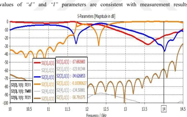
Figure 22. Reflection and Transmission Coefficients for Transition of Transceiver Structure. ... 39
Figure 23. (a) Transmitter Antenna and (b) Receiver Antenna Slots. ... 42
Figure 24. Overall Design of Transmitter and Receiver Antenna Structures. ... 43
Figure 25. Production Version of Antennas’ CST MWS Design. ... 44
Figure 26. Fundamental Dimensions of Transmitter Antenna. ... 45
Figure 27. Fundamental Dimensions of Receiver Antenna. ... 45
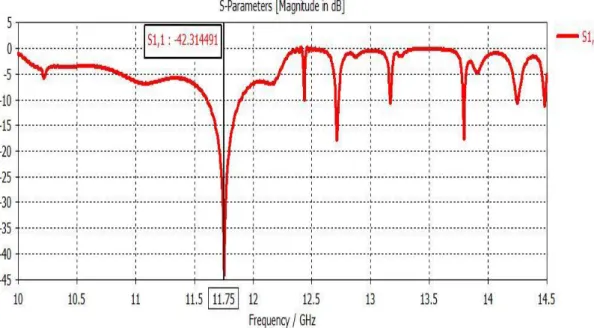
Figure 28. S11 Graph of Transmitter Antenna in CST MWS. ... 47
Figure 29. S11 Graph of Transmitter Antenna Production Version in CST MWS. ... 47
Figure 30. Transmitter Antenna Power Dissipation Graph in CST MWS. ... 48
Figure 31. S11 Graph of Receiver Antenna in CST MWS. ... 49
Figure 32. S11 Graph of Receiver Antenna Production Version in CST MWS. ... 49
Figure 33. Receiver Antenna Power Dissipation Graph in CST MWS. ... 50
Figure 34. 3D Radiation Pattern of Transmitter Antenna in CST MWS. ... 51
Figure 35. Polar Radiation Pattern of Transmitter Antenna (a) in Azimuth Plane and (b) in Elevation Plane in CST MWS. ... 51
Figure 36. Cartesian Radiation Pattern of Transmitter Antenna (a) in Azimuth Plane and (b) in Elevation Plane in CST MWS. ... 52
Figure 37. Cartesian Radiation Pattern of Production Version of Transmitter Antenna (a) in Azimuth Plane and (b) in Elevation Plane in CST MWS. ... 53
Figure 38. 3D Radiation Pattern of Receiver Antenna in CST MWS. ... 54
Figure 39. Polar Radiation Pattern of Receiver Antenna (a) in Azimuth Plane and (b) in Elevation Plane in CST MWS. ... 54
Figure 40. Cartesian Radiation Pattern of Receiver Antenna (a) in Azimuth Plane and (b) in Elevation Plane in CST MWS. ... 55 Figure 41. Cartesian Radiation Pattern of Production Version of Receiver Antenna (a) in
Figure 42. Axial Ratio of Transmitter Antenna (a) in Azimuth Plane and (b) in Elevation
Plane in CST MWS. ... 57
Figure 43. Axial Ratio of Production Version of Transmitter Antenna (a) in Azimuth Plane and (b) in Elevation Plane in CST MWS. ... 58
Figure 44. Axial Ratio of Receiver Antenna (a) in Azimuth Plane and (b) in Elevation Plane in CST MWS. ... 59
Figure 45. Axial Ratio of Production Version of Receiver Antenna (a) in Azimuth Plane and (b) in Elevation Plane in CST MWS. ... 60
Figure 46. Fabricated Receiver Antenna. ... 62
Figure 47. S11 Measurement of Prototype Receiver Antenna in Yasar University Antenna and Microwave Laboratory. ... 62
Figure 48. S11 Graph of Receiver Antenna Prototype. ... 63
Figure 49. Farfield Measurements of Prototype Receiver Antenna at (a) Azimuth Plane and (b) Elevation Plane in İYTE Anechoic Chamber. ... 64
Figure 50. Polar Farfield Gain Pattern in (a) Azimuth and (b) Elevation Planes of Receiver Antenna Prototype. ... 65
Figure 51. Cartesian Farfield Gain Pattern of Receiver Antenna Prototype in (a) Azimuth Plane and (b) Elevation Measurements. ... 66
Figure 52. Cartesian Axial Ratio Graph of Receiver Antenna Prototype in (a) Azimuth Plane and (b) Elevation Measurements. ... 67
Figure 52. Overall Design of Transceiver Antenna Structures. ... 70
Figure 53. The Dimensions of Transceiver Antenna. ... 72
Figure 54. S11 Graph of Transceiver Structure. ... 73
Figure 55. Polar Farfield Gain Graph of Transceiver Structure in (a) Azimuth and (b) Elevation Planes at 11.75 GHz. ... 74
Figure 56. Cartesian Gain Graph of Transceiver Structure in (a) Azimuth and (b) Elevation Planes at 11.75 GHz. ... 75
Figure 57. Axial Ratio of Transceiver Structure in (a) Azimuth and (b) Elevation Planes at 11.75 GHz. ... 76 Figure 58. Polar Gain Graph of Transceiver Structure in (a) Azimuth and (b) Elevation
Figure 59. Cartesian Gain Graph of Transceiver Structure in (a) Azimuth and (b) Elevation Planes at 14.00 GHz... 78 Figure 60. Axial Ratio of Transceiver Structure in (a) Azimuth and (b) Elevation Planes at
LIST OF TABLES
Table 1. TM Mode pnm Values inside the Circular Waveguide. ... 30
Table 2. TE Mode p’nm Values inside the Circular Waveguide. ... 32
Table 3. Calculated Wavelength Values for Different Propagation Modes at Transmit and Receive Frequencies in Circular Waveguides. ... 32 Table 4. Results of Study vs. Similar Studies in Literature. ... 61
SYMBOLS AND ABBREVIATIONS ABBREVIATIONS:
RF Radio Frequency
LHCP Left Hand Circular Polarization RHCP Right Hand Circular Polarization LOS Line of Sight
TT&C Tracking Telemetry & Command
TTC&M Tracking Telemetry Command & Monitoring IMUX Input Multiplexer
OMUX Output Multiplexer DHU Data Handling Unit TC-TX Transmitter Test Cap TC-RX Receiver Test Cap LPF Low Pass Filter BPF Band Pass Filter DUT Device Under Test NA Network Analyzer AR Axial Ratio
TEM Transverse Electromagnetic TE Transverse Electric
CHAPTER ONE INTRODUCTION
1.1. Scope of the Thesis
In satellite communication, satellite/spacecraft positions with respect to earth can not be exactly known at time interval between satellite/spacecraft launch from the earth and its settlement to the desired orbit. This is due to random angular motion of the satellite throughout this duration; thus, the aspect angle of the satellite/spacecraft is expected to be usually random and fluctuating with respect to earth. Even if the position of the satellite/spacecraft is random; earth station must communicate with satellite/spacecraft in order to provide proper arrangement of orientation of the satellite to its orbit. During this period, the communication from satellite to earth station is provided via a transmitter antenna, which sends signals continuously. Besides, when a satellite/spacecraft reaches to its orbit, it sends an arrival message to earth station by the transmitter antenna in general satellite applications. The orientation of the satellite/spacecraft is adjusted with a command, which is sent from earth station to the satellite/spacecraft and gathered by a receiver antenna on the satellite. Since the angular position of the satellite; consequently, the positions of transmitter and receiver antennas are random with respect to earth station, these antennas should have radiation pattern characteristics allowing transmission and reception at any aspect angle. This radiation characteristic is called as nondirectional or uniform pattern, and it belongs to an isotropic antenna. However, isotropic antenna is a hypothetical (imaginary) antenna such that real (practical) antennas do not have perfect nondirectional pattern, i.e., they have some directionalities to certain angles somehow (Balanis, 2005).
Omnidirectional antennas are very good candidates for the desired uniform radiation pattern such that they have very good (but not perfect) nondirectional characteristics. The antennas possess almost perfect uniform pattern at one principal plane (usually at the azimuthal plane) and moderate directional behavior at the other plane (usually at elevation plane). Omnidirectional antennas are frequently employed in satellite
communication systems as transmitter, receiver or transceiver antennas in order to supply uninterrupted connection between earth station and satellite/spacecraft without any significant power fluctuation. Omnidirectional patterns of these antennas make the connection between earth station and satellite/spacecraft highly independent from the instant aspect angle of the satellite/spacecraft.
Polarization mismatch (loss factor) between antennas causes an important loss especially in satellite communication systems. In a communication system with two stations being transmitter and receiver stations, when one station is fixed and the other station is mobile, one antenna has linear polarization and the other has circular polarization. This situation results in a reasonable signal level collected by the system regardless of the aspect angle of the mobile station antenna with respect to fixed antenna station. In telemetry and telecommand applications of satellite communication systems, the polarization of the transmitter and receiver antennas on the satellite are usually selected to be circular. When the antennas on the satellites belong to circular polarization, the linearly polarized incoming/outgoing signal can be received/transmitted in any orientation angle without any significant power changes (Stutzman, Thiele, 2013). Therefore, the received or transmitted signal level do not decrease significantly due to polarization loss for random aspect angles of the satellite/spacecraft along the time interval between the satellite/spacecraft is launched and settled to its orbit. The transmitter antennas on the satellite used for telemetry purpose have usually single circular polarization (left hand circular polarization-LHCP or right hand circular polarization-RHCP) due to limitation in the RF power generation. The receiver antennas on the satellite used for telecommand purpose can have single circular polarization; but they are preferably designed to give dual circular polarization (LHCP and RHCP at the same time) in order to maximize received RF power.
This thesis strives to design antennas, which can be employed in satellite communication systems as receiver (telemetry) and transmitter (telecommand) antennas. It is aimed that the antennas, which are designed, should have sufficient performance for the usage in satellite communication applications. Therefore, properties of the antennas are determined by taking general requirements and standards of satellite communication applications into account. It is decided that the antennas must have omnidirectional radiation pattern and circular polarization in order to operate effectively during from the launch of the satellite to settlement of its orbit with
proper angle. Additionally, it is aimed that antennas to be compatible as physically with satellite communication systems. Therefore, the connection port of antennas is selected as standard rectangular waveguide WR75, which is frequently used in satellite communication systems.
1.2. Motivation and Literature Search
Omnidirectional antennas are usually employed in order to provide uninterrupted connection between transmitter and receiver systems one or both of which are mobile. In this thesis, these systems are earth station part and satellite/spacecraft part where satellite part of the communication is mobile. According to definition (Balanis, 2005), the omnidirectional radiation pattern is the one having nondirectional (uniform) pattern characteristics in azimuth plane [𝑓(∅), 𝜃 = 𝜋/2] and directional pattern characteristics in the elevation plane [𝑓(𝜃), ∅ = 𝑐𝑜𝑛𝑠𝑡𝑎𝑛𝑡] for the geometry and axes given in Figure 1.
Figure 1. Omnidirectional Antenna Pattern (Balanis, 2005).
It is emphasized in (Shafai, Sharma and Rao, 2013) that the common types of antennas used in satellite systems are the omnidirectional transmit and receive antennas and the wide coverage receive and transmit horn antennas. No single antenna can achieve nondirectional (spherical) radiation in the presence of large scattering objects, such as spacecraft earth panel, structures, and waveguide feeds, it is augmented with one or more additional antennas of different configuration and combining each pattern to
form a composite radiation pattern that satisfies the spacecraft requirements in terms of antenna coverage angles and gain to provide positive radio link performance (Shafai, Sharma and Rao, 2013).
One way to acquire nondirectional (spherical) pattern is the usage of two identical hemispherical antennas, which are constituted with the addition of metallic rings around a circular aperture antenna (Lim, Nyambayar, Yun, Kim, Ahn, Bang, 2014). These antennas are placed such that one is on top platform and the other is on the bottom platform of the satellite, which results in full space (nondirectional) coverage as stated in the study of (Turkmen and Secmen, 2016) as given in Figure 2(a). Hemispherical antennas are generally used to make radiation in the satellite communication in a volume covering the elevation plane of 0° < 𝜃 < 90° and the azimuth plane of 0° < 𝜙 < 360° according to the geometry in Figure 1. However, the gain of these hemispherical antennas can be as low as -10 dBi at the boundary points (𝜃 = 90°). Besides, the addition of metallic rings around circular aperture makes the antennas occupying larger space in area.
(a) (b)
Figure 2. Full Space Coverage Methods (a) Using Two Identical Hemispherical
Antennas (b) Using Two Identical Omnidirectional Antennas.
The full space coverage can be also obtained by using two identical omnidirectional antennas, which is preferred way in this thesis. The omnidirectional antennas designed
in this thesis are realized by placing slotted antenna circular array around a circular waveguide. They are generally utilized to give radiation in the satellite communication in a volume covering the elevation plane of 45° < 𝜃 < 135° and the azimuth plane of 0° < 𝜙 < 360° consistent with the geometry in Figure 1. In order to obtain full coverage with two identical omnidirectional antennas, they must be placed on the platform as perpendicular to each other as given in Figure 2(b). At the edge regions (𝜃 = 45° 𝑜𝑟 𝜃 = 135°) , the gain can be around -5 dBi, which is higher than the minimum gain of hemispherical antennas used for the same purpose. Besides, the omnidirectional antennas stated in this thesis have more compact structure as compared to the hemispherical antennas. This is because the omnidirectional ones contain one circular waveguide and a disk around it to provide circular polarization, which gives smaller physical cross section than that of the hemispherical antennas. The higher minimum gain and being compact structure are some of the reasons why the omnidirectional antennas are preferred instead of hemispherical ones. Omnidirectional antennas used in satellite communication systems are more common in American market, while hemispherical antennas are commonly used in European market.
It is stated in (Stutzman, Thiele 2013) that circularly polarized antennas are desired to use in satellite communication systems. Because, the wave from a linearly polarized antenna on a spacecraft will rotate due to motion or Faraday rotation in the ionosphere, but if a circularly polarized antenna is used, the incoming linearly polarized wave orientation angle will not lead to power level fluctuations. Even though a 3-dB signal loss encountered, the received signal remains constant. Satellites move with respect to ground stations. Some geometric differences may vary because of the small changing the position of the satellite with respect to ground station. In addition to atmospheric effects, geometric changings effect to communication system efficiency. Circular polarization keeps constant signals regardless of these anomalies. Circularly polarized antennas provide high performance point-to-point long run connections due to linear noise rejection. If there are any reflection in communication path, one polarization is outperform the other. Besides other RF signals in the communication path can be isolated by using a polarization in the opposite predominant high level signals. When a RF signals reflect from a smooth surface, 180⁰ phase difference may occurs. This is a phenomena, which is known as specular or mirror image reflection. The reflected
signal may create destructively or constructively effect on Line Of Sight (LOS) signal. Circular polarization is used to this situation as an advantage since the reflected wave would have a different sense than the direct wave and block the fading from these reflections.
In literature, there are circularly polarized waveguide antennas but most of these antennas have not omnidirectional or hemispherical radiation pattern. Especially, the circularly polarized slot antenna array on rectangular waveguide type antennas exist in literature. However, these antennas based on this technique can not provide desired omnidirectional radiation pattern due to physical structure of the rectangular waveguide (Gao, Luo and Zhu, 2014).
The circular polarization can be achieved for the hemispherical antennas mentioned above with a septum polarizer, which is a microwave component attached just before the hemispherical antenna. The septum polarizer is a special component, which converts linear polarization of the rectangular waveguide or coaxial cable to the circular polarization of the square waveguide or vice-versa (Bornemann, Amari, Uher, Vahdieck, 1999), (Bertin, Piovano, Accatino, Mongiardo, 2002), (Zhong, Li, Fan, Shen, 2011). However, the septum polarizer should be carefully and specially designed to give sufficient circular polarization within the desired bandwidth, which makes the design of circularly polarized hemispherical antenna much more complex.
In this thesis, the circular waveguide slotted antenna array with omnidirectional radiation pattern is preferred. The other reason of the selection of omnidirectional antenna in addition to higher minimum gain within the coverage and compactness is the simple design to give circular polarization as compared to hemispherical antenna. In omnidirectional antenna used for the satellite communication purpose in this thesis, the polarization of the circular waveguide slotted antenna can be adjusted just with the slope of the antenna slots and the radius of metallic ring plates added around the circular waveguide. Therefore, circular polarization can be obtained by arrangement of these parameters, which results in a much simpler design.
Although there are some similar studies, there is not enough study about circularly polarized omnidirectional antennas in literature, which increases the novelty and contribution of the study performed in this thesis. The thesis is aimed to improve the results of the other similar studies. From the literature search result, there are two
similar studies, which can be taken as comparison for this thesis. The results that belong to first of these studies is given by Top and Dogan give -10 dB frequency bandwidth is about 1.005%. The gain is greater than 1 dBi in the -10⁰/+30⁰ elevation plane sector. The ripple of gain in azimuth plane is about +/- 0.75 dBi, which corresponds to 1.5 dBi gain variation. The axial ratio in azimuth plane is better than about 3.5 dB. The axial ratio in elevation plane better than 4.2 dB in -10⁰/+30⁰ and 6 dB in the -25⁰/+89⁰ region. The results that belong the other study is given by Masa-Campos, Fernandez, Sierra-Perez and Fernandez-Jambrina give -10 dB frequency bandwidth is about 1.4%. The gain is about 0.5 dBi in the azimuth plane with measured maximum ripple is 1.9 dBi. Axial ratio in azimuth plane is 3.2 dB, with a ripple of 1.5 dB. The antenna designs in this thesis are going to be shown to give wider -10 dB frequency bandwidth, smaller gain variation and better axial ratio performance. The antenna designs/studies expressed in above paragraph including the first two antennas designed in this thesis are used only for transmitting or receiving purpose on the satellite. They can not be used to operate for transmitting and receiving purpose at the same time, in other words, transceiver purpose. This is because the transmitter and receiver frequencies in satellite communication are sufficiently far away so the antennas designs described above can not cover that kind of wide bandwidth. To the best of our knowledge, a single circularly polarized omnidirectional waveguide antenna covering both transmitter and receiver frequencies of satellite communication is not found in literature. In this thesis, as the last and most novel design among three designs, a single antenna structure is also carried out to give circularly polarized omnidirectional pattern in both transmitter and receiver frequencies by using a dual band technique rather than wideband technique.
1.3. Thesis Overview and Outline of the Thesis
In the thesis, a single transmit antenna, a single receive antenna and a transceiver antenna (transmit and receive structures together) designs are proposed. The configuration of each structure is given. It is followed by the explanations about proposed antenna operations. The design steps as well as the parametric antenna structures/studies are constructed. Then, some parametric optimizations are implemented on the structures, and it is understood which antenna property is affected by which parameter in the design from the optimization study. The optimization
process continues until the desired antenna results are achieved. After the optimization process, only the prototype of the proposed receiver antenna is manufactured. The measurements of prototype are performed in Antenna and Microwave Laboratories of Yasar University and Izmir Institute of Technology (IYTE). Measurements and simulation results are compared to each other for the confirmation of results. Afterwards, the evaluation of the proposed antennas is given. Finally, the study is concluded, and the comments of proposed antennas are supplied.
This thesis can be examined in the six chapters; structures of satellite communication systems, electromagnetic mode conversions and transitions between waveguide components, separate transmit and receive antenna design, combined transceiver antenna design.
In Chapter 2, it is included overview satellite communication systems, fundamental components, required antenna parameters and electromagnetic mode conversions. Chapter 3 focuses physically and electromagnetically transitions between rectangular waveguide to circular waveguide.
Chapter 4 explains the design of transmit and receive antennas, which have separate structures to each other.
Chapter 5 gives the design of transceiver antenna, which is obtained by the combination of transmit and receive antenna structures.
CHAPTER TWO
THE STRUCTURE OF SATELLITE COMMUNICATION SYSTEMS
2.1. Satellite Communication Systems Overview
The satellite communication systems can be divided into two main part as; space segment and the ground segment. A simple representation of a space segment is shown in Figure 3. Position information is sent from satellite to ground station by telemetry system. The position information is processed on ground station and required commands, which provide correct settlement of satellite to its orbit, are sent back to satellite from ground station by telecommand systems.
Figure 3. Satellite Communication System (Ippolito Jr, 2008).
Space segment consists one satellite or a group of satellite and ground station, which provides the operational control to keep the satellites safely in orbit. The ground station
is variously referred as the Tracking, Telemetry, Command (TT&C) or the Tracking, Telemetry, Command and Monitoring (TTC&M) station (Ippolito Jr, 2008). The satellite must contain a platform and a payload. The payload is composed from receiving and transmitting antennas with all other electronic communication equipment that provide carrier signal transmission. The organization chart of a sample payload is shown in Figure 4.
Figure 4. A Payload Organization Chart (Maral, Bousquet, 2010).
On the payload shown Figure 4 carrier signal, which comes from uplink system, is amplified, and it is frequency down converted. The isolation between input (received) signal and output (transmitted) signal is provided by this frequency conversion. Payload bandwidth is divided into some sub-bands. Bandwidth division is realized with input multiplexer (IMUX), which consists of a group of filter. Output carrier signal that are amplified are recombined via output multiplexer (OMUX).
Ground segment includes all data traffic in earth stations. It includes three basic types of terminals as; fixed (in-place) terminals, transportable terminals and mobile terminals. These terminals mostly connected to end users via terrestrial networks or small stations. An organization chart of an earth station is given in Figure 5. TTC&M ground stations are not a part of ground segment depicted in Figure 5.
Figure 5. The Organization Chart of an Earth Station (Maral, Bousquet, 2010). Operating frequency is one of the most important design and performance parameter in satellite communication systems. When determining the free space wavelength of carrier signals, the atmospheric effects and other losses that may be occurred in communication path must be taken into consideration. In addition, there are some international and domestic regulations about operating frequency of satellite communications. The designers of satellite communication system must comply with these restrictions.
2.1.1. The Structure with Separate Transmitter and Receiver Antennas
In satellite ground stations, separate transmitter and receiver antennas can be employed together. In Europe, Ku-band downlink (transmitter) frequency band is used from 10.7 GHz to 12.75 GHz for direct broadcast satellite services, while the usable frequency band is generally between 12.75 GHz and 14.5 GHz for uplink (receiver). In satellite communication, the frequency pair selected for downlink/uplink (or transmit/receive)
of a specific satellite application is not selected close to each other such that at least 1.5-2 GHz difference between uplink and downlink frequencies is selected both for transponder or telemetry/telecommand purposes (Ulaby, Ravaioli, 2014). By using different frequency bands for Earth-to-satellite uplink segments and for satellite-to-Earth downlink segments, it is guarded against interference between the two (transmit and receive) signals. The downlink segment uses lower-frequency carrier than the uplink segment, because lower frequencies suffer lower attenuation by Earth’s atmosphere, thereby easing the requirement on satellite output power where the transmit frequency of 11.75 GHz and receive frequency of 14 GHz used in this thesis also satisfies all of these requirements/restrictions described above.
The design of two separate antennas for two different frequencies is easier than the design of a single antenna (transceiver) structure, which includes transmit and receive part of the TT&C systems. Four separate antennas, two of which should be the receiver and the other two should be transmitter, must be used in this configuration. Besides, different RF front-end topologies between antennas and payload must be used for transmitter and receiver antenna structures. The schematic views of RF front-end structures corresponding to transmitter antennas and receiver antennas of telemetry and telecommand applications are given in Figure 6 and Figure 7, respectively. RF circuit diagram of the transmitter block is given in Figure 6. Data Handling Unit (DHU) produces two carrier signals, which have different frequencies of “f1” and “f2” within the downlink frequency band of 10.7-12.75 GHz. DHU carries data between electronic units on satellite and ground segment via TT&C subsystem. Signal processing in TT&C subsystem of satellite communication is done within the electronic circuits, which are parts of DHU. The carrier signals “f1” and “f2” is amplified inside Payload. The amplified “f1” and “f2” signals are firstly divided by two channels by hybrid coupler, which has two input and two output ports.
Figure 6. RF Circuit Diagram with Separate Transmit Antennas.
The hybrid coupler is also known as -3dB coupler and it divides to power of signal that travels inside of the waveguide up into two equally portions. In addition, the hybrid coupler can create phase difference that desired. Then, half of the “f1” and “f2” signals are summed on output ports of the hybrid coupler. The sum of “f1” and “f2” signals on the output ports of the hybrid coupler must be filtered with a Bandpass Filter (BPF) or a Low Pass Filter (LPF). This is because higher order harmonics of these signals may occur while they are travelling on RF circuit. Before the signals are transmitted from antenna, they pass from a test coupler that belongs to transmitter (TC-TX). Signals power values can be measured by test coupler. Finally, the signals radiate from the transmitter antennas to free space.
In the settlement of the antennas, two transmitter antennas are used, which are placed perpendicular to each other in order to provide full space coverage as shown in Figure
6. The antennas are positioned to satellite platform with 45⁰ angle. Thus, the reflection from the other components of the satellite can be reduced.
RF circuit diagram of a receiver block is given in Figure 7. According to the selected uplink frequencies (f1 and f2) within uplink frequency band of 12.75-14.5 GHz, the each antenna in Figure 7 can receive the signal of one frequency or multiple(double) frequencies. If the selected frequencies are very far away from each other, typically 1 GHz, such that a single antenna can not cover that kind of wide bandwidth, each antenna can receive the signal of only one of the uplink frequencies. Here, two nonidentical antennas in Figure are used, one of which operates at f1 and the other is designed to obtain the signal of f2. If the frequencies are employed sufficiently close –on the order of a few 100 MHz-, each antenna in Figure can get the signals of all frequencies, and they are designed to be identical.
The receiver blocks of these two different cases can receive single carrier signal (f1 or
f2) or double carrier signals (f1 and f2) simultaneously. These operations are required
different RF circuit diagrams from each other. Receiving single carrier signal RF circuit diagram is shown in Figure 7 with black color, while receiving double carrier signals is shown in Figure 7 with blue color.
Figure 7. RF Circuit Diagram with Separate Receive Antennas.
In receiving of single carrier signal RF circuit diagram, the signal with frequency of
“f1” is taken by one of the antennas, and “f2” is taken by other antenna from free
space. Then, they convey to test coupler (TC-RX). Signals power values can be measured by TC-RX. “f1” and signals “f2” that come from TC-RX blocks of different and nonidentical antennas are collected in a combiner called as output multiplexer (OMUX) structures. Task of OMUX is to combine signals to feed antenna networks. As the output of combiner or OMUX, there exist the signals of “f1” and “f2”, which is obtained by combining of two incoming signals. However, the power level of one frequency is much more dominant to other according to aspect view of the antennas with respect to earth station. Therefore, practically, there is only one frequency at the output of OMUX. Before “f1” OR “f2” signal reaches to DHU, it is passed from BPF,
which should allow “f1” and “f2” in its bandpass region. Finally, “f1” or “f2”signal reaches to DHU, and it is processed in this block.
The RF circuit diagram for the receiving of double carrier signals, which is frequently preferred method as compared to that of single carrier signal, is a little bit different from the gathering of single carrier signal. The main difference between the reception of double carrier signals and the reception of single carrier is the usage of hybrid coupler instead of combiner (OMUX). Incoming signals that are “f1 and f2”, come from TC-RX blocks are divided by two inside hybrid coupler. It can be observed summation of half of the “f1 and f2” at each output ports of the hybrid coupler. BPF are applied to hybrid coupler outputs. First BPF is selected according to frequency of
“f1” and the other is selected according to frequency of “f2”. As result of this filtering
operation, there is only half of “f1” signal on one of the DHU input port and there is only half of “f2” signal on the other input port of DHU.
Two carrier signals can be received with a single system. But power of each carrier signals reduce to their half. In receiving single carrier process, it must be used combiner or OMUX structures instead of hybrid coupler. These structures are more complicated than hybrid coupler and cost of receiver block may be increased by using these complicated structures. There are some advantages and disadvantages of using, receive double carrier signals blocks instead of receive single carrier signal blocks. Designer have to decide which one is proper to system according to system properties.
2.1.2. The Structure with One Transceiver Antenna
In some satellite systems, transmit and receive antennas are designed as a single structure, which includes transmitter part and receiver part inside of it. This kind of structures are called as transceiver. Design and production of transceiver structures are more sophisticated than separate receiver and transmitter structures. Also transceiver RF circuit diagram is more complicated than separate transmitter and receiver structures. However, using single transceiver antenna reduces the number of the antennas that must be mounted on the satellite platform. RF circuit diagram that belongs to transceiver blocks is given in Figure 8.
Figure 8. RF Circuit Diagram of Transceiver Antennas.
Transceiver blocks RF circuit diagram can be investigated as two parts, which are transmitter blocks and receiver blocks. Transmit part of the RF circuits is indicated with blue blocks, receive part of the RF circuits is indicated with black blocks. Receive and transmit parts of transceiver RF circuit are inverse of each other.
In transmitter part of the RF circuit, the signals are produced by the DHU. Then, the signals, which are produced by DHU, are divided into two by Hybrid Coupler, and halves of each carrier signals are summed on the output ports of Hybrid Coupler. These signals pass in TC-TX blocks. Power levels of the signals can be measured in these blocks. Then the signals convey to diplexers, which are a crossover filters. Diplexers are employed for decoupling two channels via frequency difference. Thus, different signals that have different frequencies can be transmitted and received in a single antenna as in Figure 8.
As it is mentioned before, receiver part of the RF circuit operates as inverse of the transmitter part that is explained. Carrier signals from the antennas convey to diplexers.
Diplexers provide decoupled two different frequency channels, which are transmitter channel and receiver channel. Received carrier signals go through in receiver channel of the diplexers. Then carrier signals pass inside TC-RX blocks. Power levels of carrier signals can be measured in these blocks. Carrier signals, which include two different frequency components, are divided into two inside of Hybrid Coupler. Half of the each frequency components of the carrier signal are summed on the output ports of Hybrid Coupler. These signals that summed are filtered by BPF. This filtering operation separates frequency components of the carrier signals to each other. Half of the each frequency components of the carrier signals are given to DHU as inputs.
2.2. General Antenna Parameters
Aperture type antennas are commonly employed in satellite communication systems. Generally, antenna apertures are placed XY plane in coordinate system, which is shown in Figure 9.
Figure 9. Aperture Antenna Coordinate System (Dybdal, 2009).
XY plane in this figure is scanned by ϕ angle (0 ≤ ϕ ≤ 360°), and called as azimuth plane. The other fundamental plane is represented with θ angle (0 ≤ θ ≤ 180°), and called as elevation plane. These terms are frequently used for explaining properties that related with radiation pattern. Besides, S-parameters are often used for representations of return loss.
2.2.1. Return Loss
All component in electronic have an impedance value. In satellite communication systems, it is aimed to transmit a signal with low loss as much as possible. For providing maximum power transfer, impedance of components that connected to each other must be match. Mismatch loss is generally expressed with scattering matrix
parameters. The reflected signals can be expressed in terms of voltage or power value. Coefficients that belong to reflection are denoted by S11 parameter. Coefficients that belong to transmission are denoted by S21 parameter. Relation between impedances and S11 parameter is expressed as;
|𝑺𝟏𝟏| = 𝑽𝟎 − 𝑽𝟎+ = 𝒁𝑳− 𝒁𝟎 𝒁𝑳+ 𝒁𝟎 (1)
Return Loss (RL) in dB is expressed in terms of S11 parameter as;
𝑹𝑳(𝒅𝑩) = −𝟐𝟎 𝐥𝐨𝐠(|𝑺𝟏𝟏|) (2)
At high frequencies, measurement of total voltage, current and power on a network port is very hard. It is not possible to use proper probe for each impedance value of networks. Even if a measurement probe that has proper impedance is connected to circuit, it may cause oscillation or self-destruction on the circuit. S-parameters do not required to connection of undesired loads to the device under test (DUT). In S-parameter measurement, multiple devices can be cascaded to predict overall systems performance. S-parameters are measured with network analyzers (NA).
2.2.2. Directivity and Gain
The directivity of an antenna, D, is simply defined as “the ratio radiation intensity in a given direction from the antenna to radiation intensity averaged overall directions” (Balanis, 2005). Maximum directivity, which is the maximum value of the directivity function and also usually called as the directivity, can be expressed mathematically as;
𝑫𝒎𝒂𝒙 = 𝑼𝒎𝒂𝒙 𝑼𝟎 = 𝟒𝝅𝑼𝒎𝒂𝒙 𝑷𝒓𝒂𝒅 (3)
Here, in order to find average radiation intensity (U0) in equation (3), total radiated power (Prad) in equation (3) is divided by 4𝜋.
Gain is a similar parameter with directivity. The ratio between the radiated power from the antenna of a system to the transmit (generated) power of antenna gives total system efficiency. The system efficiency represents with a coefficient, which is 𝒆𝟎. Gain of antenna is calculated with directivity of antenna in given direction.
𝑮 = 𝑫𝒆𝟎 (4)
2.2.3. Polarization
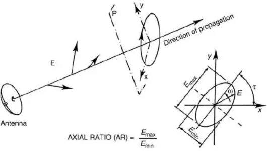
Radiated electromagnetic wave consists electric field component and magnetic field components. Electric field vector and magnetic field vector are orthogonal and perpendicular to the direction of the wave propagation. Polarization can be defined as orientation of the electric field in one RF cycle as it can be seen it Figure 10. There are three type of polarization, which are linear polarization, circular polarization and elliptical polarization. Linear and circular polarizations are special cases of elliptical polarization. Antenna parameter, which determines type of polarization, is axial ratio. Axial ratio is expressed as,
𝑨𝑹 = 𝑬𝒎𝒂𝒙 𝑬𝒎𝒊𝒏
(5) In general the ratio of major axis to minor axis, gives elliptically polarization. If the ratio of major axis to minor axis is zero (AR = 1 = 0dB), polarization becomes circular. If ratio of major axis to minor axis is infinity (AR = ∞, direction of the electric field is fixed), polarization becomes linear.
Figure 10. Polarization of Propagating Wave (Maral, Bousquet, 2010).
Ideally, a circularly polarized wave’s AR must be 0 dB. In literature, electromagnetic wave, which has AR between 0 dB and 3 dB, is accepted as circularly polarized.
When the electromagnetic wave is travelling toward to observer, if electric field vector rotates clockwise, it is called as left-hand polarized. If it rotates counterclockwise, it is called as right-hand polarized.
Transmit and receive antennas are desired to have circular polarization. Because, the wave from a linearly polarized antenna on a spacecraft will rotate due to motion or Faraday rotation in the ionosphere, but if a circularly polarized antenna is used, the incoming linearly polarized wave orientation angle will not lead to power level fluctuations. Even though a 3- dB signal loss encountered, the received signal remains constant (Stutzman, Thiele, 2013).
2.3. Rectangular and Circular Waveguides
Structures, which enable propagation electromagnetic waves with minimum energy loss by restricting expansion dimensions, are defined as waveguide. There are many different kinds of waveguide in literature but only rectangular and circular ones are employed in this study. Electromagnetic waves can travel inside of waveguide in different modes. These modes can be listed as transverse electromagnetic (TEM), transverse electric (TE) and transverse magnetic (TM). Transition between different kinds of waveguide is possible. Also conversion between different modes can be applied with special mode converter structures.
Waveguides structures provide an interface between antennas and overall system. Different waveguide dimension standards exist for providing integration between structures that are designed and different systems. Waveguide dimensions, which are standard, are selected according to operating frequency. Operating frequency value must be between lower and upper cutoff frequencies of waveguide in desired mode. In this study, rectangular waveguide is selected as WR75, which is a standard rectangular waveguide. It is used as an interface between system and antennas.
2.3.1. Rectangular Waveguide
Rectangular waveguide is a fundamental waveguide type in transmission of microwave signals. Standard rectangular waveguides can operate from 1 to 220 GHz. In market, many rectangular waveguide components are available such as couplers, attenuators, isolators, detectors, slotted lines as commercial products. Only electromagnetic waves that have TE and TM modes can propagate inside of the
rectangular waveguide. Electromagnetic wave that has TEM mode cannot propagate inside of rectangular waveguide.
Figure 11. A Rectangular Waveguide (Balanis, 2005).
The antennas designed in thesis are designed to operate at 11.75 GHz (transmitter) to 14 GHz (receiver) at Ku-Band. WR75 rectangular waveguide is commonly used as standard waveguide in Ku-Band satellite communication, where all microwave and antenna components of the topologies described in Figure 6, Figure 7 and Figure 8 are generally connected together with these waveguides. This standard waveguide will be also used as the feeding waveguide of the antennas designed in this thesis. Thus, practically, the designed antennas can be easily connected to other components behind the antennas.
It is expected that only TE10 dominant mode should operate within rectangular waveguide in order to give a single mode operation. The dimensions of WR75 rectangular waveguide are given as a = 19.05 mm (long edge) and b = 9.525 mm (short edge). The lower and upper operating frequency values of a rectangular waveguide can be practically evaluated such that the operating frequency should be at least 25% above the cutoff frequency of the TE10 mode but no higher than 95% of the next higher cutoff frequency which is TE20 or TE01 mode for WR75 rectangular waveguide (Cheng, 1993). By using this explanation, the boundaries of the frequency band is calculated as
𝒄 𝟐𝒂× 𝟏. 𝟐𝟓 = 𝟑 × 𝟏𝟎𝟖 𝟐 × 𝟏𝟗. 𝟓 × 𝟏𝟎−𝟑× 𝟏. 𝟐𝟓 = 𝟗. 𝟖𝟒 𝑮𝑯𝒛 (6) 𝒄 𝟐𝒃× 𝟎. 𝟗𝟓 = 𝟑 × 𝟏𝟎𝟖 𝟐 × 𝟗. 𝟓𝟐𝟓 × 𝟏𝟎−𝟑× 𝟎. 𝟗𝟓 = 𝟏𝟓 𝑮𝑯𝒛 (7) As it is mentioned before, WR75 standard rectangular waveguide operates at only TE10 dominant mode, whose field distribution is shown in Figure 12. The frequency interval is found to be from 9.84 GHz to 15 GHz, which includes transmit (11.75 GHz) and receive (14 GHz) frequencies in this thesis.
Figure 12. Electric (solid curves) and Magnetic Field (dash curves) Representation of TE10 Dominant Mode of a Rectangular Waveguide (Pozar, 2012).
2.3.2. Circular Waveguide
Circular waveguide is a hollow metal pipe. It supports TE and TM waveguide modes. The structure of a circular waveguide is given in Figure 13.
Figure 13. A Circular Waveguide (Pozar, 2012).
Inner radius “a” of circular waveguide determine the operating frequency and active modes that can travel inside of circular waveguide. The actual dominant mode inside of the circular waveguide is TE11. Slotted antennas on circular waveguide must feed as symmetrically in order to provide non-directional radiation pattern. Slotted antennas array on circular waveguide can not be fed as symmetrically with TE11 mode. Therefore, slotted antennas are desired to be fed by TM01 dominant mode, which is known as symmetric mode. Mode conversion between dominant modes is possible via special converter structures to be explained. Three modes are going to be handled and will be important in the designs of the proposed antennas. These modes are the dominant TE11 mode, symmetric TM01 mode and the next possible higher order mode of TE21 according to the radius of the circular waveguide. The electric and magnetic field lines of these three modes are graphed out in Figure 14 where dash curves correspond to magnetic field lines. When the magnetic field lines of the TM01 mode are examined, it can be seen that these lines have circular symmetry. Therefore, these magnetic field lines create circularly symmetric current densities on the wall of the conductor of circular waveguide. Consequently, the slots placed on the circumference of a circle at the conducting wall have almost same excitations, which results in a uniform (non-directional) radiation at the plane where the slots are placed.
Figure 14. Field Lines of Some Circular Waveguide Modes (Balanis, 2012).
2.3.3. Rectangular to Circular Waveguide Transition
As it is mentioned before, the dominant mode without mode convertors in circular waveguide is TE11 mode. This modeis not a symmetrical mode as shown in Figure 14. The slotted antenna array must be fed as symmetrically in order to provide non-directional radiation pattern. The most suitable mode to feed slotted antenna array on circular waveguide is TM01 mode as described in the previous section. There are some special transition techniques, which can be employed for mode conversion while providing transition between rectangular waveguide and rectangular waveguide. Four-transition types are given Figure 15.
(c)
(d)
Figure 15. Excitation of TEmn and TMmn Modes in a Circular Waveguide (a) TM01 Mode, (b) TE10(rectangular) – TE11(circular), (c) TE10(rectangular) – TM01(circular)
(Balanis, 2012), (d) TE10(rectangular) – TM01(circular) (Silver, 1949)
It is predicted that the structures given in Figure 15(c) and Figure 15(d) can provide the transition between circular waveguide and rectangular waveguide for the desired mode conversion between TE11 mode of rectangular waveguide to TM01 mode of circular waveguide. Among these structures, the one in Figure 15(c) has the limitation about the selection of the diameter of the circular waveguide, which can be the dimension of the broadwall of WR75 waveguide, 19.05 mm, at most. It is going to be shown that this diameter dimension is not enough for the designed antennas in this thesis. Then, the study focuses on the structure given in Figure 16.
Figure 16. Transition Structure Rectangular and Circular Waveguides in This Thesis (Silver, 1949).
In order to provide the desired transition between rectangular and circular waveguides, minimum return loss can be provided by adjusting two parameters. These parameters can be listed as the diameter of the circular waveguide “d” and the distance “l” between the center of the rectangular waveguide and short end of circular waveguide described in Figure 16.
CHAPTER THREE
DESIGN OF THE RECTANGULAR TO CIRCULAR WAVEGUIDE TRANSITIONS
As it is emphasized before, transition between rectangular to circular waveguides is provided by special transition structures as shown in Figure 15. In this thesis, slotted antenna array, which is on the circular waveguide walls, is decided to feed by a symmetric mode. TM01 mode, which is selected as symmetrical mode, is employed to feed slotted antenna array. In Figure 14 field lines of some modes that belong to electromagnetic waves, which propagates in circular waveguide, are given. From given field lines, only field lines of TM01 mode have symmetry property. Omnidirectionality of the antennas can be provided by symmetry property of the TM01 mode. Other modes that are not symmetric may disrupt the omnidirectionality of the antennas. For this reason, while electromagnetic wave propagate with TM01 mode inside circular waveguide, TE11 and TE21 modes, which are not symmetric, must be suppressed.
The main motivation of this chapter is to design rectangular to circular waveguide transitions for the feed of the slotted array antennas at satellite communication frequencies. In the design, it is desired to provide TM01 mode propagation and suppress to TE11 andTE21 modes in circular waveguide as much as possible. In this sense, two design parameters, which first one is diameter of the circular waveguide the other one is the distance between center point “P” of rectangular waveguide in Figure 16 and short circuit at the end of the circular waveguide, must be determined.
The first fundamental design parameter of rectangular to circular waveguide transition is diameter of the circular waveguide given in Figure 16. It is expected that the electromagnetic wave propagate inside of circular waveguide with TM01 mode. In order to provide maximum power transfer at the rectangular to circular transition, impedance value of circular waveguide should be match according to TM01 mode of the electromagnetic wave. In order to increase the bandwidth of the transition, the diameter of the circular waveguide “d” is selected as half of the guided wavelength
that belongs to symmetric mode TM01,i.e.λg,TM01/2, (Silver, 1949). As a result, the diameter of “d” can be evaluated for any center frequency of the design by using the formula of guided wavelength and other relation equation as (Pozar, 2012);
𝝀𝒈,𝑻𝑴𝟎𝟏 = 𝟐𝒅 = 𝟐𝝅 𝜷 (8) 𝜷𝑻𝑴,𝟎𝟏= √𝒌𝟐− 𝒌𝒄𝟐, { 𝒌 = 𝟐𝝅𝒇 𝒄 𝒌𝒄 = 𝒑𝟎𝟏 𝒅 𝟐 ⁄ (9) √(𝟐𝝅𝒇 𝒄 ) 𝟐 − (𝟐 × 𝒑𝟎𝟏 𝒅 ) 𝟐 = 𝝅 𝒅 (10)
This system of equations gives relation between circular waveguide diameter and specific frequency values. There is only unknown parameter in equation set, which is
“p01”. This parameter represents TM01 mode inside circular waveguide and it can be found from Table 1.
Table 1. TM Mode pnm Values inside the Circular Waveguide.
In the study, the circular waveguide, which is a part of transition structure between waveguides, is terminated with a short circuit as given in Figure 16. The second fundamental design parameter of this study is distance between short circuit and “P” point, which is rectangular waveguide center. The distance is indicated by “l” in Figure 16. Suppression of non-symmetric modes can be provided by the adjustment of the distance “l”. It is known that electromagnetic wave propagates with TE11 dominant mode inside circular waveguide. Therefore, in this study it is primarily targeted to suppress TE11 mode. The distance “l” can be selected as quarter wavelength (λg,TE11/4), which belongs to TE11 dominant mode inside circular waveguide for the suppression TE11 dominant mode. The suppression is provided by transforming short circuit (at the
conducting cap of the bottom side of the circular waveguide) to very large impedance (open circuit) to the output of the rectangular waveguide by selecting l = λg,TE11/4. Since this impedance should be evaluated as a series element to the circular waveguide, almost no power of TE11 mode propagates towards the circular waveguide. However, when l is selected as λg,TE11/4, this length corresponds to almost λg,TM01/6 for the desired TM01 mode. Consequently, the short circuit at the bottom wall is transformed to not exactly open circuit but again large impedance, which results in the reduction on the power of TM11 mode through the circular waveguide. Therefore, the selection of l = λg,TE11/4 effectively suppresses the effect of the undesired TE11 mode but also the desired TM01 mode.
The distance “l” can be also selected as 3λg,TE11/4. Selection of “l” distance to be as (3λg,TE11/4) is more effective than selection of “l” distance to be as (λg,TE11/4) for suppression of non-symmetric modes. This is because when “l” distance is equal to (3λg,TE11/4), it is also equal to λg,TM01/2, which makes transformation of the short circuit again to the short circuit for TM01 mode at the output of rectangular waveguide. Now, the selection of l = 3λg,TE11/4 effectively suppresses only the effect of the undesired TE11 mode but not the desired TM01 mode. In this situation, TM01 mode of electromagnetic wave is sufficiently transferred to the circular waveguide. “l” value can be expressed as,
𝝀𝒈,𝑻𝑬𝟏𝟏= 𝟐𝝅 𝜷 (11) 𝜷𝟏𝟏 = √𝒌𝟐− 𝒌 𝒄 𝟐, { 𝒌 = 𝟐𝝅𝒇 𝒄 𝒌𝒄 = 𝒑’𝟏𝟏 𝒅 𝟐 ⁄ (12) 𝜷𝟏𝟏 = √(𝟐𝝅𝒇 𝒄 ) 𝟐 − (𝟐 × 𝒑’𝟏𝟏 𝒅 ) 𝟐 (13) 𝒍 = 𝟑 × 𝝀𝒈,𝑻𝑬𝟏𝟏 𝟒 = 𝟔𝝅 𝟒 √(𝟐𝝅𝒇𝒄 ) 𝟐 − (𝟐 × 𝑷’𝒅 𝟏𝟏) 𝟐 (14)
There is only one unknown parameter that is 𝒑’𝟏𝟏. This parameter can be found from Table 2. Different “l” values can be calculated for each frequency values from the given expressions.
Table 2. TE Mode p’nm Values inside the Circular Waveguide.
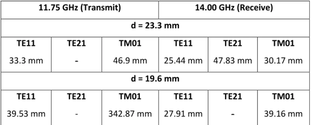
Transmit and receive frequencies are selected as 11.75 GHz and 14 GHz, respectively. By using the equation set from (8)-(10), diameter values of circular waveguides are determined for transmitter structure and receiver structure respectively as d = 23.3 mm and d = 19.6 mm. Wavelengths of the propagation modes can be calculated by using Equation 8 and Equation 11. Wavelengths depended on frequency, diameter of the circular waveguide and coefficient that belongs to propagation mode. These coefficients are found from Table 1 and Table 2. Table 3 is constructed for the first three modes to be considered in the antenna designs by using all these information. Values, which are line on them, cannot propagate over given frequency and diameter values.
Table 3. Calculated Wavelength Values for Different Propagation Modes at Transmit and Receive Frequencies in Circular Waveguides.
11.75 GHz (Transmit) 14.00 GHz (Receive) d = 23.3 mm TE11 33.3 mm TE21 - TM01 46.9 mm TE11 25.44 mm TE21 47.83 mm TM01 30.17 mm d = 19.6 mm TE11 39.53 mm TE21 - TM01 342.87 mm TE11 27.91 mm TE21 - TM01 39.16 mm
3.1. Design for Transmitter Structure
Transmit frequency is given as 11.75 GHz. There are two fundamental parameters in rectangular to circular waveguide transition. These are diameter of the circular
waveguide “d” and the distance between short circuit that is located end of the circular waveguide and rectangular waveguide center point where located intersection rectangular and circular waveguides. For calculation these parameters with respect to different frequency value and different operating modes, some MATLAB scripts are generated. As result of MATLAB calculation initial value of circular waveguide diameter is found “d = 23.3 mm” and “l =25 mm“.
The calculated “l” and “d” values are used as initial values in Computer Simulation Technology (CST) designs. CST MWS is a simulation software program, which provides design antennas or microwave components and it makes electromagnetic simulations of structures that are designed. CST MWS simulations of structures are done with a workstation, which has 128 GB RAM, in Yasar University Antenna and Microwave Laboratory.
Firstly, rectangular to circular waveguide transition structure, which is decided to employ, is drawn in CST MWS with calculated initial values of “l = 25 mm” and “d
= 23.3mm”. Then structure that designed is simulated. Until simulation results are
satisfied to expectations, simulations are repeated. Optimizer and parameter sweep tools of CST MWS are used in iterations of optimization.
Figure 17. Rectangular to Circular Waveguide Transition That Designed for Transmitter Structure.
At the end of the iterations of optimization in CST MWS, final values of circular waveguide diameter and distance between P point and short circuit that is located end of the circular waveguide are found as, “d = 23.4 mm and l = 24.6 mm” as consistent