FIBER OPTIC LIGHTING SYSTEMS
*Munir BATUR
1, Ufuk PARALI
1,Osman N. UCAN
11
Istanbul Aydin University, Electrical and Electronics Engineering Department, Florya,
Istanbul, Turkey
E-mail: [email protected], [email protected], [email protected]
Abstract
- Recently there have been many important and valuable developments in the communication industry. The huge increase in the sound, data and visual communications has caused a parallel increase in the demand for systems with wider capacity, higher speed and higher quality. Communication systems that use light to transfer data are immensely increased. There have recently many systems in which glass or plastic fiber cables were developed for light wave to be transmitted from a source to a target place. Fiber optic systems, are nowadays widely used in energy transmission control systems, medicine, industry and lighting. The basics of the system is, movement of light from one point to another point in fiber cable with reflections. Fiber optic lighting systems are quite secure than other lighting systems and have flexibility for realizing many different designs. This situation makes fiber optics an alternative for other lighting systems. Fiber optic lighting systems usage is increasing day-by-day in our life. In this article, these systems are discussed in detail.Keywords: Optic, Photonics, Illumination
*New Generation Led Lighting R&D and Measurement Laboratory Project has been funded by Istanbul Development Agency under Year 2011 istanbul environmental and energy-friendly financial support program for businesses
1. INTRODUCTION
Light wave communication was first considered more than 100 years ago. The implementation of optical communication using light waveguides was restricted to very short distance prior to 1979. Coming glass company achieved a breakthrough in 1970 by producing a fused silica(SiO2) fiber with a loss approximately 20 dB/km. The development of semiconductor light source also started to mature at about that time, allowing the feasibility of transmission over a few kilometers to be demonstarted. Since 1970, the rate of technological progress has been phenomenal, and optical fibers are now used in transoceanic service. Besides the long-distance routes, fibers are used in inter exchange routes, and the subscriber loop in the final link in what will eventually be the global interconnection chain. Optical fibers are associated with high-capacity communications. A lot of attention is presently being given to optical fibers to provide a very extensive broadband ISDN.
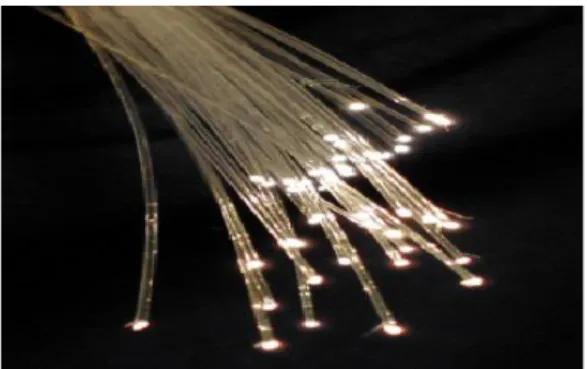
Fiber optics is defined as that branch of optics that deals with the transmisson of light through ultrapure fibers of glass, plastic or some other form of transparent media. From a decorative standpoint most of us are familiar with the fiber optic lamp, which uses bundles of thin optical fibers illuminated from the base end of the lamp by a light source [1].
The light source is made to vary in color, which can be seen at the apposite ends of the fiber as tree of illuminating points radiating various color of the transmitted light. Although the lamp is used for decorative purposes only, it serves as an excellent model of how light can be transmitted through the fiber.
2. FIBER OPTIC LIGHTING
Fiber Optic Lighting is used to provide intense, cool illumination for a number of optical or imaging applications. Fiber Optic Lighting often consists of fiber optic illuminators integrated with one or more light guides that direct illumination towards a specific application. Fiber Optic Lighting offers multiple illumination tools with only a single light source through the selection of various adapter heads for fiber optic light guides [2].
2.1 How Fiber Optic Lighting Works
A light shines into the end of the fiber optic tube, making a beam that travels down. As it moves down the fiber optic line, the beam scatters but the coating reflects it back, sending it down the tube without losing any light. When the light reaches the end of the fiber optic tube, it continues to travel forward, making a little point of light. If a section of the cable is uncovered, some of the light will
408 leak out of it, since there is no reflective coating to
send it back into the cable [3].
2.2 Types of fiber
There are two types of light emitting fiber.
2.2.1 End-Emitting Fiber
This fiber has a transparent core with a thin transparent cladding or exterior that traps all the light in the core so that all the light directed into the fiber make it out the other end. This insures that maximum light is transmitted through the fiber to the light fixture on the other end.
Figure 1: End-Emitting Fiber
2.2.2 Edge-Emitting Fiber
This fiber is very similar to the end-emitting fiber except that cladding or exterior does not trap all the light and allows some of the light to escape the fiber. This causes the fiber to glow and looks very much like a neon light tube [4].
Figure 2: Edge-Emitting Fiber
2.3 Basic Elements of Fiber Optic Illuminating System
Fiber optic illuminating system basically consists of two parts as light generator and fibre Cable harness used for transmitting this light.
Connectors ( Muff, multi connector) are used to mount fibre cable harness to the light source. Connectors function as a metal compression (jointer) ring. When the fibres coming out of the connectors are needed to be used for illuminating different areas meters apart from each other, then the fibres going to the same goal can be grouped in one case in order to ease the application.
If requested, terminator and lens systems can be used on the end of the optic cable harness, depending on the need and the place of use of the setup.
On cutting off the optic fibres, special cutter devices are used on the end of fibre to prevent any malformations which cause loss of light. After cutting the fibres, before it combines to the light generator in a multiple connector (connecting muff), the ends should be rubbed up and brightened in order to transmit the light more homogeneously.Sections of the fibre optic illuminating system are shown in Figure 3.
Figure 3: Sections of the fibre optic illuminating
system 2.3.1 Light Generator
Light generator is the heart of the fibre optic illuminating system and is equipped with a special source of light. Fibre cable harness, designed and produced as for meeting the very need, connects to the light generator from outlet through multiple connectors. Generally two different kinds of bulbs can be used in light generators; 1) high pressure white heat halogen lamp containing halogen gasses or 2) a metal type lamp with Hi-Intensity Discharge (HID). Color circle in a closed box. The fan used insinde, preventsthe cable harness to be damaged because of the heat in the light source by ventilating the hot air out of the generator and prolongs the system's life expectancy. Depending
409 on the diameter of a fibre which is used, It is
possible to transmit light from a light genertor ranging to almost 1000 points. Reflector helps to focus and send the light coming from the Intensive Light smart bulbs to the multiple connector (combining muff) on the head end of the fibres. Generally 12V lamps with 30, 50, 75 and 100 W halogen and 150-250 W metal halogen formed lamps are used in a light generator. Light generators are produced in suitable types for insinde and outside atmosphere. Outer metal sections are Painted with elektrostatic paint , and inner parts are nikel plated by electrolysing. Connectors of light generators in which the fiber optic cables to connect, are manufactured by aluminium for the reason of being resistant to heat. Light sources of medium and high power has focus setting. Also, light generators possess soil protection, severe heat protection and current limiting fuses. Besides standard mono Color illuminating, to attain more dynamic and attractive illuminating image, Color discs are placed in the system. Generally a Color engine functioning about 2 to 4 RPM revolutions is used to revolve the Color disc. Certain Color changings with certain gaps, color changings according to music rhythm or time, speed of Color change, its order and the choice of the Color steps are all adjusted according to the color engine features.
2.3.2 Halogen Light Generators
Light is produced by halogenic bulbs in Halogen light generators. Generally they are designed with 20W, 35W, 50W, and 75 W power potencies. Bulbs life expectancy ranges within 3000-5000 hours. Light generators of over 35 W are cooled with axial flow fans, and make almost 30 dB noise. These generators can be designed in different types according to intensity of light ranging to 6.000 cd and 16 000 cd. Color temperatures of 3000-3200 Kelvin are standard but it is possible to reach 5000 Kelvin color temperature with special bulbs.
2.3.3 Metal Halide Light Generators
In Metal Halide Light generators light is produced by metal halide bulbs. They are generally designed with 75W, 100 W, 150 W and 250 W power potencies. Life expectancy of the bulbs differenciates within 6000-8000 hours. Metal halide light generators are cooled by axial fans and make about 40 dB noise. They can be designed in different types ranging 24000 cd - 160 000 cd according to the light intensity. Their standard Color temperature is 4000-5000 Kelvin [5].
Light Generator
Fiber Type Fiber Diameter The maximum Length Application Area 30-50W End-to-Radiance
1-6 mm 3-6 m Stars effect or 2-3 m showcase 75W/9-10mm
End-to-Radiance
2-6 mm 9-12 m Decorative or functional lighting
75W 25mm
End-to-Radiance
4,5-6 mm 6-8 m Room lighting, decorative lighting
150W
End-to-Radiance
4,5-6 mm 16-18 m Outdoor lighting front, beam
150W
End-to-Radiance
3-6 mm 10- 13 m Decorative lighting, big star effect 75W/9 mm Sideways Radiance >4,5 mm 12-20 m Decorative lines, 75W/9 mm Sideways Radiance
4.5 mm 9-12 m Low-ligting (for example cinema) linear
75 W/28 mm Sideways Radiance
>4.5 mm 9-14 m Low light levels linear 75 W/28 mm Sideways
Radiance
4.5 mm 7-12 m Low-ligting(for example cinema) linear
410 Tab le I. Len ghth s and appl icati on areas of optic cables according to the light generator.
2.3.4 Optic Cable Harness
Optic Cable harness is used for carrying the produced light from light generator to the area of use. In optic fiber illuminating system, both acrylic (PMMA) (plastic) and glass fibres are used, but plastic fibres are prefered more frequently to make the application easier and durable. The fibres in a fiber harness can be of different lenghths and thickness. The system is totally formed according to the desired target points' light level and form. Fibres are produced by making the highly heated sticks thin in the revolving mills and covering them with other shield during this process. In fiber optic illuminating applications, generally 1 mm active diameter cables (except case) are used, if requested, fiber number can be increased to 15 mm diameters. Work temperature of plastic optic fibres used in illuminating ranges between -50 degrees to + 70 degrees. moreover they can bear up, in short time period ( less than a minute) to 100 degrees temperature. Glass optic fibres with 110 degrees work temperature are more durable against heat. In addition, plastic optic fibres have protective case retarding burning, and glass optic fibres have firefree feature.
One of the most important points to be taken care while planing a fibre optic illuminating project is the choice of suitable wavelenght to use optic fibres. While plastic optic fibres carry light better at 600 nm wavelenght (blue/green Color spectrum), glass optic fibres have the feature of carrying light better at 670 nm wavelenght (Red/yellow Color spectrum)
Both types of the optic fibre can be useable for about 20 years unless they are not exposed to demolishing external effects.
Along side the features stated above, glass optic fibres are more attenuating than plastic optic fibres.
For both types of optic fibres, attenuation comparison measured according to the lenght is presented in further chapters. Despite the
superiorities, plastic optic fibres are prefered more in illuminating rather than glass optic fibres becausethey are cheaper due to their raw material and production technique.
There are two different options for applying fibres to the multi connector. The first is to place the multi connector to the harness output in classical method. Second and more developed method is called random layout method. By laying the different diameters' fibre ends of a harness out randomly into multi connector, more homogeneous light can be achieved from 2 mm and more diameter fibres. By this means more homogeneous light delivery can be possible at points where general illuminating and spot effect usage is subjected [6].
2.4 Fiber Optic Lighting Advantages
No electricity at the point of illumination- fiber
optic cables carry only light to the point of illumination.The illuminator and the electricity that powers it can be many yards away from the objects or areas being lit.
No heat at the point of illumination - fiber optic
cables carry no heat to the point of illumination
No UV rays at the point of illumination - fiber
optic cables carry no destructive UV rays to the point of illumination, which is why the world's great museums often use fiber optic lighting to protect their ancient treasures. For preserving fragile and precious items, fiber optic systems provide bright but gentle light.
Easy and/or remote maintenance - whether the
issue is access or convenience, fiber optic systems can make re-lamping a breeze. For fixtures that are
150 W Sideways Radiance >4.5 mm 12-18 m Decorative effects 150 W Sideways Radiance 4.5 mm 10-16 m Decorative effects 150 W Sideways Radiance 4.5 mm 15-20 m Decorative effects 150 W Sideways Radiance 4.5 mm 15-20 m Decorative effects 150 W Sideways Radiance
411 difficult to access, the illuminator can be located in
a place that's easier to reach, and for multiple small lights (stair lights, paver lights or chandeliers) changing a single illuminator lamp re-lamps every light at once [7].
3.EXPERIMENTS OF MEASURING FIBER OPTIC LIGHTING
3.1 The Power Consumption of the Light Source [8]
Figure 4:The power consumption of the light source(Istanbul Aydın University LED Lighting Laboratory)
Figure 5: Volts/Amps/Hertz(Istanbul Aydın
University LED Lighting Laboratory)
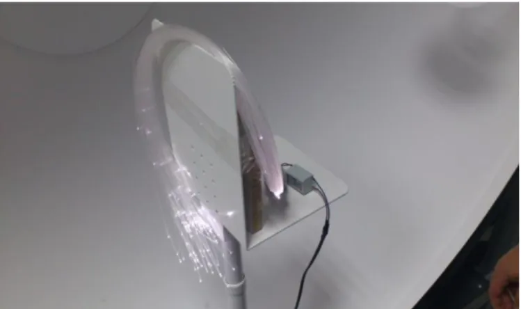
3.2. Measurement of all the Fibers (Sphere System)
Figure 6: Measurement of all the Fibers (Istanbul Aydın University LED Lighting Laboratory) Derived Data
Parameter Scan 1
Radiant Flux (Watts) 0,03
Luminous Flux (lumens) 9,51 Scotopic Luminous Flux (lm') 19,88 Chromaticity x coord 0,3166 Chromaticity y coord 0,3258 Peak Wavelength (nm) 453,7 Center Wavelength (nm) 454 Full Width Half Max Bandwidth (nm)
21,4 Excitation Purity (%) 6,2 Correlated Color Temperature
(deg. K)
6311 Luminous Efficacy (lm/W) 4,75 Measured DUT Current (A) N/A Measured DUT Voltage (V) N/A Spectral Data
Table II. Table of values (Istanbul Aydın
University LED Lighting Laboratory)
Optical fiber source from the light source total lum/flux value 9.5 lumen. color temperature is 6311 Kelvin. Luminous efficiency was calculated as 4.75 [9].
412
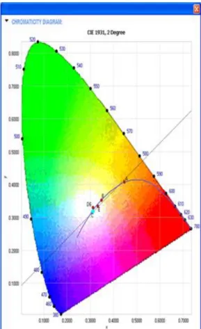
Figure 7: Chromaticity diagram(Istanbul Aydın
University LED Lighting Laboratory)
Looking at the graph x and y chormacity is clear that values greater than 0.3.[10]
3.3. Measurements of 1 Watt LED (Sphere System)
Table III. Table of values (Istanbul Aydın
University LED Lighting Laboratory)
Figure 8: Chromaticity diagram (Istanbul Aydın University LED Lighting Laboratory)
Chormacity values slightly greater than 0.3 [11].
4. CONCLUSION
In conclusion, Fiber Optic Technology is coming of age as a useful tool in the lighting designers kit. With knowledge and consideration in the design and specification and a quality product installed correctly, Fibre Optics can achieve some otherwise apparently impossible lighting results. It is not a universal solution for all our design problems and reliance on suppliers selected on cheapest price basis to provide solutions for complex problems with minimal guidance from lighting designers can result in unsuccessful installations.
5. REFERENCES
[1]Sam Hassan ‘Fiber Optic Introduction’ Fiber Optic System 1-2 (2008)
[2] Edmund Optics Inc. — 101 East Gloucester Pike, Barrington, NJ 08007-1380 USA
[3]Cramp, Jason, “How Does It Work”, Fiber
413 [4]Philips, “Fiber Optic LightingSystems”, Philips
A.Spublication.,
İstanbul, Türkiye, 5-9 (2000).
[5]Dalyanlı, H., Afsar, S., Dogan, H., “Fiber Optic Lighting”, Graduation Project, Marmara University T.E.F., Istanbul, 2-11 (2001).
[6] Mahlke, G., Gössing, P., “Fiber Optic Cables”, Rublicis MCD Verlag,
Editor: Siemens Aktiengesellschaft, Munich, 69-73 (1997).
[7]Fiber Optic Technologies Canada(2003) [8] Istanbul Aydın University LED Lighting Laboratory (2013)
[9] Istanbul Aydın University LED Lighting Laboratory (2013)
[10] Istanbul Aydın University LED Lighting Laboratory (2013)
[11] Istanbul Aydın University LED Lighting Laboratory (2013)
[12] Fiberli Lighting Systems Psl Electronic Product Catalog (2013)