©BEYKENT UNIVERSITY
DIRECT TORQUE CONTROLLED INDUCTION
MOTOR DRIVES WITH CONSTANT
SWITCHING FREQUENCY STRATEGY
H. Ibrahim OKUMUS
1, D. HOLLIDAY
21Karadeniz Technical University, Department of Electrical and Electronics Engineering, 61080 Trabzon, TURKEY, E-mail : [email protected]
2University of Bristol, Department of Electrical and Electronics Engineering, Bristol, UK, E-mail : [email protected]
Received: 6 September 2007, Accepted: 31 October 2007
ABSTRACT
Although direct torque control (DTC) has some attractive features such as lesser parameter dependence, fast dynamic response, and no requirement for mechanical rotor position sensor for the inner torque control loop there exist some problems such as the relatively large torque ripple in a low speed range and switching frequency variations according hysteresis band amplitudes and the motor operating speed. To solve these problems a constant switching frequency torque controller is proposed to replace the conventional hysteresis-based controller. The strategy proposed modulates the torque error with a high frequency carrier signal resulting in a constant torque switching frequency that improves the performance of the D T C by combining a low-torque-ripple characteristic in steady state with the fast torque dynamics. Experimental results prove the applicability of the proposed strategy clearly as compared with the conventional method.
Keywords: Constant switching frequency, Direct torque control, Induction
motor drives, Torque ripple
ASENKRON MOTOR SÜRÜCÜLERİ İÇİN SABİT
ANAHTARLAMA FREKANSLI DOĞRUDAN
MOMENT KONTROLÖR
ÖZET
kalmaktadır. Bu sorunlar; Özellikle düşük hızlarda aşırı moment dalgalanmaları ve çalışma hızına bağlı olarak ortalama anahtarlama frekansındaki değişimler olarak ortaya çıkmaktadır. Bu sorunları çözmek için bu çalışmada, geleneksel DTC de kullanılan histerezis bant kontrolör yerine sabit anahtarlama frekanslı moment kontrolör önerilmektedir. Önerilen yöntemde yüksek frekanslı taşıyıcı işaretle moment hatası modüle edilmekte ve sonuçta ortalama sabit anahtarlama frekansı elde edilerek DTC performansı arttırılmaktadır. Yapılan çalışmada elde edilen deneysel sonuçlar, önerilen yöntemin geleneksel yönteme göre daha iyi ve uygulanabilirliğini göstermektedir.
1. INTRODUCTION
Recent advances in power semiconductor and microprocessor technology have made the advanced control techniques possible to be applied to ac motor drive systems. DTC has become a popular technique for the control of induction motor drives as it provides a fast dynamic torque response and robustness to machine parameter variations without the use of current regulators [1], [2]. In principle, DTC method is based on instantaneous space vector theory. By optimal selection of the space voltage vectors in each sampling period, DTC achieves effective control of the stator flux and torque. Thus, the number of space voltage vectors and switching frequency directly influence the performance of DTC control system.
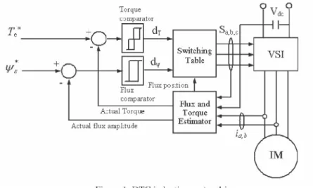
The DTC technique can be implemented easily using two hysteresis controllers (one for flux and another for torque) and a switching table to select the switching voltage vector as shown in Figure 1. [3],[4].
However, conventional DTC suffers from such effects as torque ripple and variable switching frequency. The inverter switching frequency is related to the torque and the flux hysteresis bandwidth. Small torque hysteresis band amplitude determines higher switching frequency. The stator flux vector locus approaches a circle and the phase current waveform is nearly sinusoidal [5], [6]. These operating conditions determine low harmonic copper losses in the machine and high switching losses in the inverter. As the torque hysteresis bandwidth increases the switching frequency decreases and stator flux vector locus degenerates to a hexagon. These operating conditions require the smallest number of commutations in each fundamental period. Furthermore, torque hysteresis bandwidth mostly affects the harmonic distortion for small values of torque hysteresis bandwidth [3], [5].
The basic constant hysteresis band control is affected by the drawbacks of variable switching frequencies and of heavy interferences in the three-phase
system with isolated neutral. These drawbacks cause more sub-harmonics, higher load current ripple and variable switching losses in the inverter when compared to the inverters with fixed PWM switching frequencies [7]-[10]. In order to control the total harmonic distortion (THD) of the phase current it is necessary to fix the flux hysteresis band.
In the conventional DTC strategy a hysteresis band comparator is popularly used for the torque control due to its simplicity of implementation, fast torque control response and peak torque limiting capability. However, this strategy with a fixed hysteresis band suffers from variable switching frequency, as a function of motor speed, stator and rotor fluxes, and stator voltage. As a result, higher torque ripple is generated, especially at low speeds. Variation of the torque switching frequency also causes more sub-harmonics in the phase current and variable switching losses in the inverter when compared to fixed switching frequency PWM. The thermal limitations of the power switching devices are also important and must be considered in design process. A fixed torque hysteresis comparator bandwidth is determined for the worst case power device switching losses. The switching frequency is therefore not optimised for other operating conditions. Several studies have been carried out to achieve the constant switching frequency in DTC [7], [11]-[17]. In this paper a constant torque switching frequency strategy, which minimises torque ripple whilst maintaining constant switching frequency is proposed. The strategy modulates the torque error with a high frequency carrier signal resulting in a constant torque switching frequency that improves the performance of the DTC by combining a low-torque-ripple characteristic in steady state with the fast torque dynamics.
2. GENERAL DESCRIPTION OF DTC
Conventional Direct Torque Control is presented in Figure 1. The core of the system consists of a flux and torque estimator, a flux controller, a torque controller, an optimum switching table and a three-phase voltage source inverter (VSI) [18], [19].
In a three-phase voltage source inverter (VSI) there are three legs and six power switches (three upper and three lower switches). The instantaneous voltage space vectors of the 3-phase PWM VSI are determined by the status of the switching states Sa, Sb, and Sc. Using these switching functions, the voltage space vectors of the 3-phase VSI are given by.
V k =2Vd fS + Sba + S a2] where a = ej2n/3 and k = 0,1,2,...7. ( 1 )
Figure 1. DTC induction motor drive.
The switching states of the phases a, b, and c of the VSI are defined in Table 1. Table 1. Switching pattern of voltage vectors
k
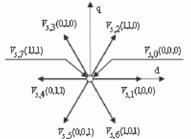
Sb Sc 0 0 0 0 1 1 0 0 2 1 1 0 3 0 1 0 4 0 1 1 5 0 0 1 6 1 0 1 7 1 1 1There are 8 possible vectors, Vs,k(Sa, Sb, Sc), k = 0,1,2,...7, two of which are zero voltage space vectors Vs>7(1,1,1) and Vs>0(0,0,0). The others are the nonzero voltage space vectors, Vs1(1,0,0), Vs6(0,1,0), as shown in Figure 2. In general, the magnitude of each non-zero space vector is the same (i.e. 2/3 Vdc) with a phase of ( k - 1 ) n (where k = 1, 2, . 6 ) .
Figure 2. Switching-voltage space vectors.
In DTC, optimum switching vector selection is essential. An optimum voltage switching vector look-up table gives the optimum selection of the switching vectors for all the possible stator flux-linkage space-vector positions (six positions, corresponding to the six sectors). The optimum switching vector selection table is shown in Table 2. Voltage vectors are selected depending upon flux and torque errors, and upon which sector the stator flux vector currently occupies. Table 2 indicates that any possible combination of torque and stator flux demands in any sector can be fulfilled simultaneously by selecting one of the 8 possible voltage vectors. When a stator flux increase is required then stator flux error status dv = 1 and if a stator flux decrease is required then dv = 0. The notation corresponds to the fact that the output signals of the two-level flux hysteresis comparator are dv, where
y
= 1 y = 0if
if¥ sref
> A y / 2 ¥ sref - ¥ s < - A y / 2 Table 2. Switching tabledy dT Sector 1 Sector 2 Sector 3 Sector 4 Sector 5 Sector 6 1 V2(110) V3(010) V4(011) V5(001) V6(101) V1(100) 1 0 V7(111) V0(000) V7(111) V0(000) V7(111) V0(000) -1 V6(101) V1(100) V2(110) V3(010) V4(011) V5(001) 1 V3(010) V4(011) V5(001) V6(101) V1(100) V2(110) 0 0 V0(000) V7(111) V0(000) V7(111) V0(000) V7(111) -1 V5(001) V6(101) V1(100) V2(110) V3(010) V4(011)
3. PROPOSED TORQUE SWITCHING STRATEGY
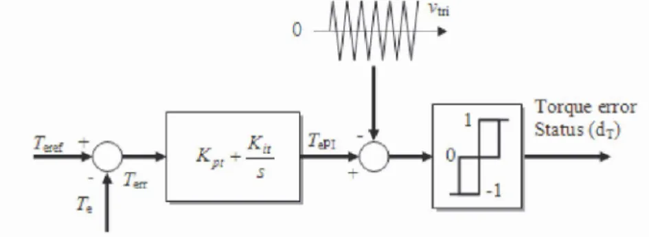
The proposed torque control strategy consists of a carrier signal generator, a comparator and a PI regulator as shown in Figure 3. The carrier signal generator generates a high frequency triangular waveform. The principle of operation of the proposed torque controller can be described with the aid of the block diagram shown in Figure 3. The torque reference (Ter e f) is compared with the actual torque to produce an instantaneous torque error (rerr), which is then fed to a proportional-integral (PI) controller. The integral term in the PI controller improves the tracking by reducing the instantaneous error between the reference and the actual torques. The resulting error signal (TePI) is modulated by the high frequency triangular carrier signal to produce a torque error status at steady-state operation.
In principle, the output of the proposed torque controller is similar to that of a three level hysteresis band controller. The output of the torque controller, which is called "torque error status" (dT), is used in the VSI switching table shown in Table 2, resulting in the optimum selection of the switching vectors for all possible stator flux positions. The torque error status can be one of three states: 1, 0 or - 1 . If the torque is required to be increased then dT(t) = 1, if the torque is required to be decreased then dT(t) = - 1 , and if no change in the torque is required then dT(t) = 0. When dT(t) = 1 or - 1 , then active voltage vector is selected and when dT(t) = 0, a zero voltage vector is selected. The notation corresponds to the fact that the instantaneous outputs of the proposed torque controller are dT(t), where for forward rotation of the motor rotor
Torque error Status ( dT)
Figure 3. Proposed torque control scheme.
- 1 if -TePI < Vtri
dr(t)
= A
0 if -TePI > Vtri and for backward rotation of the rotor
dx(t) =
1 if TePI > Vtri 0 if TePI < Vtri
3.1. TORQUE SWITCHING ANALYSIS
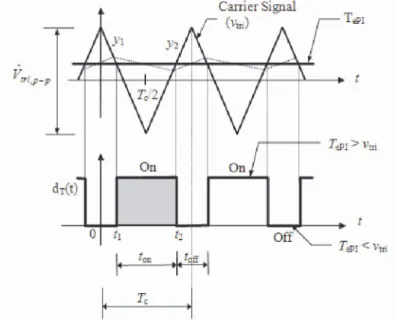
In the constant torque switching frequency strategy, the signal that controls the state (1, 0, - 1 ) of the torque switching is generated by comparing a control signal TePI with a fixed-frequency triangular waveform as shown in Figure 4. As stated earlier the control signal is obtained from the PI controller in Figure 3. The frequency of the triangular carrier signal with constant peak to peak amplitude, which is shown in Figure 4, establishes the switching frequency. A care must be given to the design of the PI controller so that the slope of TePI does not exceed the triangular carrier slope.
Carrier Signal
ïéPI'Vtri
T&i < Vnj
3.2. TRANSFER FUNCTION OF TORQUE ERROR
MODULATION
For slow variation in duty ratio D(t) and provided that
— V
tri p—p< T
ePI< V
tri p , the transfer function between TePI and D can be derived based on Figure 4 as follows:The equations of the straight lines y1 and y2 in Figure 4 are written as:
y i = — 2 ^ t + Vtn,p—p ( 2 )
T c
y 2 = 2 ^ t — !/„•, p—p (3)
From Figure 4, the triangular wave intersects y1 and y2 at t = t1 and t = t2
respectively. By substituting TePI, t1 and t2 into (2) and (3), t1 and t2 can be written as: TePI = — 2 h + Vtri, p—p (4) T c —
T + V
• t - ePI + v tri, p—p T • • l1=
~ Tc ( 5 ) 12V
tri, p—p t.
c TePI = 2 h — Vtri,p—p (6) TcT + V
. . epI + v tri,p—p T..
12 = - V - Tc (1) tri, p—pThe continuous duty ratio D(t) is therefore given by:
1 t+Tc
D(t) = —
\dT(t) dt =
(8)Tc t Tc
Substituting (5) and (1) into (8) and re-arranging terms gives:
D (t) = ^"1,P—P + TePI + TePI — Vtri, p—p )Tc ^
•'• D ( t) - V TePI ( 1 0 )
tri, p—p
As shown in Equation (10), the relation between D(t) and TePI is a pure gain
1
with a value of — . Therefore the Laplace transform of (10), yields the
V •
tri, p—pfollowing transfer function.
D(s) = 1
(11)TePI Vtri,p—p
3.3. THE SLOPE OF TORQUE VARIATION BY ACTIVE
AND ZERO VOLTAGE VECTORS
From Figure 5, the electromagnetic torque slopes f1 (positive slope due to the
non-zero voltage vectors) and f2 (negative slope due to the zero voltage vectors) can be derived using d and q components of flux and stator voltage space vectors as Te 3 P M [ I f1 + " T L~T [ VsdVrq + Vsq¥rd — ®r (WsdVrd +¥sq¥rq ) J ( 1 2 ) OT sr 2 OL s Lr
Te 3P M
f2 Z r ~ r a r (Wsd ¥rd + Vsq ¥rq ) ( 1 3 )2
where OTsr
- (L
sL
r— M
2 )/(L
sR
r+ L
rR
s ) (in which subscript k is omitted).Figure 5. Torque variation with active and zero voltage vectors in one cycle of carrier triangular wave.
Equations (12) and (13) represent the positive and negative slope of torque produced by non-zero and zero voltage vectors respectively. As it can be seen in Figure 5, with a small sampling time A t , slopes f1 and f2 can be considered
to be constant during the duration of A t since the dynamic response times of the flux and speed are significantly greater than a sample period.
For a small value of A t , the slope f1 in (12) and f2 in (13) can be considered as constant values during the sampling time, and then the torque increase and decrease can be approximated as a straight line as shown in Figure 5.
In the stator flux reference coordinate, the following expressions can be derived along with Equations (14) and (15).
vTd = RJSd + d ¥sd =
R
si
s + d ¥s (1 4)dt dt
< = RJSq + ®s¥sd = RJS + as ¥ s ( 1 5 )
(os = ar + as U p (16)
where the superscript " ¥ $ " denotes that the quantities are referred in stator flux reference frame and:
f s = ¥ s : stator flux amplitude
(Os : stator flux angular frequency
(Or : rotor angular frequency (rad/sec)
(slip : slip frequency
fsd = ' - f s : direct axis flux f s q =
= 0
: quadrature axis fluxUsing these expressions and assuming that the applied voltage vector is the tangential to the flux locus (vsd = 0, vsq = Vs) then Equations (12) and (13)
can be rearranged as:
fi =~— +
d f
[
[ - K )(¥,¥%)] (17)
s r
2 oL
sL
rfs
'Te 3P M
h
(ar
-®
¥ s)t¥s¥Z ) (18)
atsr 2 aLsLr
As shown in Equations (17) and (18), the torque variation is directly proportional to the stator flux angular frequency CÛ¥S. The instantaneous
angular frequency of the stator flux is the angular frequency of the stator flux when the active voltage vector is applied. In steady-state, the rotation of the stator flux stops (dT(t)=0) when a zero voltage vector is applied. The instantaneous frequency of the stator flux is thereby zero. Equation (18) then simplifies to:
Te 3P M
wf2 = T ~ T T (®r )(¥s¥¥S ) (19) (JTsr 2 OLs Lr
active voltage vector duration time, as shown in Figure 5. The average value of total instantaneous angular frequency of the stator flux per cycle is equal to the synchronous frequency and is denoted by (s (in rad/s). The number of
triangular carrier cycles within one cycle of the synchronous frequency ( s can
be calculated as NOCtri = 2nfc / (s, where fc is the triangular carrier
frequency. An active and a zero voltage vectors are selected in each cycle of the triangular carrier as shown in Figure 5.
Since each cycle of the triangular carrier has only one associated active voltage vector as shown in Figure 5, the number of the non-zero voltage vectors is equal to the number of the carrier cycles in 2 n radians. For a constant frequency of triangular wave the value of the angle Ads, shown in Figure 5,
is therefore calculated as:
2 n 2n
asAds
=
= = — (20)s
NOC
tri2nfc / ( fc
where NOCtri is the number of cycles of the triangular carrier in one synchronous frequency cycle.
In order to calculate the value of the instantaneous angular frequency of the stator flux it is necessary to find out the duration of the applied active voltage vectors in each carrier cycle. For this the relationship between the duration of the active voltage vector and the average duty ratio D(t) can, using Equation (8) and Figure 5, be given by:
. D(t)
A0s ( s/ f
cAt = ^ 1 = ^ =
(21)fc ( ¥ ( ¥
The instantaneous angular frequency of the stator flux is, using Equation (21), given by:
( ( r + (slip
®w
= ^ =
— ( 2 2 )D(t) D(t)
By substituting Equation (22) into Equation (17) the positive torque slope can be obtained as:
Te 3P M
fx = +
atsr 2 aLsLr V¥¥¥S + ( ( - ( r ) ( ¥ s ¥ ¥ S )
(23)
To simplify the Equations, (23) and (19) are rearranged as:
f2 = -AT
e- K
la
r(25)
where1 „ 3P M
vs„ 3 P M . ^
atSr 2 aLsTr 2 aLsTr
The mean value of the instantaneous torque variation for the period of the triangular carrier waveform as shown in Figure 5 is given by:
f i D + f2(1 - D)
(26)By substituting Equations (24) and (25) into Equation (26) the average value of the instantaneous torque variation is given as:
—Te = -ATeD + BV fsD + K1rns - KlarD - ATe (1 - D) - K1ar (1 - D) (27)
dt
and the equation can be simplified to:
—
dt
-Te = - ATe + BVr D + K
xa
slip(28)
4. SIMULATION AND EXPERIMENTAL RESULTS
Simulation and experimental results are presented to confirm the theoretical analysis. A brief description of the simulation and experimental set-up are given. Comparisons between conventional hysteresis based torque comparator and the proposed constant torque switching frequency strategy using the simulation and experimental results are presented.
Simulation studies for a DTC drive with the proposed torque control strategy were carried out using the MATLAB software package.
The experimental set-up of the proposed DTC motor drive system is shown in Figure 6. The machine ratings and parameter values are given in Table 3. The main components of the experimental set-up are a TMS320C31 DSP board, a standard PC and external circuitry consisting of a 64 k-words of memory with an 8-channel Analogue to Digital Converter (ADC) and 4-channel Digital to Analogue Converter (DAC). There are also gate drive circuitry and IGBT inverter power circuit. The motor driven is a standard squirrel cage induction machine coupled with a Permanent Magnet DC Generator (PMDCG) as load.
Power, PN 0.37 kW
Frequency, fN 50 Hz.
Supply Voltage (Delta/Star cont.) 0-240/380-415 V
Line current, IN (Delta/Star cont.) 1.9/1.1 A
Pole pairs, P 2
Stator resistance, Rs 28.13 O
Rotor resistance, Rr 20.76 O
Stator self inductance, Ls 0.634 H
Rotor self inductance, Lr 0.634 H
Mutual inductance, M 0.4226 H
Inertia, J 0.002 kg-m2
Figure 6. Experimental set-up.
4.1. TORQUE RIPPLE
In the proposed torque control strategy, the undesired reverse voltage vectors are selected if the output signal of the PI regulator becomes negative. This is due to the large proportional gain. This occurs at low speed since the absolute value of the positive slope of TePI is larger than the absolute value of the negative slope. This problem is illustrated by simulation results in Figure 7. The lower trace of the figure shows the torque error status, which is a three level output. This means that forward, zero and reverse voltage vectors may be selected in the forward direction. To avoid this appropriate proportional gain of the PI regulator has to be selected. Figure 8 shows the waveforms with the proportional gain reduced which clearly illustrate the reduction of the - 1
torque error status. With a small proportional gain the - 1 torque error status is almost eliminated as illustrated in Figure 9. It should be noted that the complete elimination of the - 1 torque error status is very difficult due to the ripple in the stator flux.
Figure 7. The generation of the torque error status based on the comparison between the carrier signal and the PI controller output with a large proportional gain.
1 0 0
- 1
0 . 2 0 1 0 . 2 0 2 0 . 2 0 3 0 . 2 0 4 0 . 2 0 5
05 0 . 2 0 1 0 . 2 0 2 0 . 2 0 3 0 . 2 0 4 0 . 2 0 5 Time (sec.)
Figure 8. The generation of the torque error status based on the comparison between the carrier signal and the PI controller output with an appropriate proportional gain.
0 . 2 0 . 2 0 1 0 . 2 0 2 0 . 2 0 3 0 . 2 0 4 0 . 2 0 5
0 . 2 0 . 2 0 1 0 . 2 0 2 0 . 2 0 3 0 . 2 0 4 0 . 2 0 5
Time [sec>
Figure 9. The generation of the torque error status based on the comparison between the carrier and the PI controller output with a small proportional gain.
At low speed, the positive slope of the torque waveform is large, which can result in a torque overshoot. In the hysteresis based torque controller, the torque overshoot will most likely touch the upper limit of the hysteresis band and to reduce the torque, the reverse voltage vectors will be selected. With reverse voltage vectors the torque will reduce rapidly, thus resulting in torque undershoot. Figure 10(a) shows the simulation result waveforms of the torque and the torque error status of the proposed torque controller. With the limitation of the duration of the large positive torque slope the large torque overshoot is reduced. Therefore the peak to peak torque ripple is significantly reduced, as shown Figure 10(a), when compared to hysteresis based torque controller response in Figure 10(b) and (c).
Figure 10(b) shows simulation results for the torque and the output of the torque hysteresis band controller for the hysteresis based torque controller with ATe = 0.06Nm and a rotor speed of 20 rad/s. The output of the hysteresis torque controller of '-1' indicates that the reverse voltage vectors are selected due to the overshoot and undershoot in the torque waveform and that the peak-peak torque ripple is larger than the torque hysteresis band. In conventional DTC, to avoid torque overshoot resulting from torque touching the upper hysteresis band limit, the width of the torque hysteresis band is increased. Figure 10(c) shows the simulation results waveforms of the torque and the torque hysteresis comparator output with the torque hysteresis bandwidth increased to 0.12Nm. As seen from the figure, with the increased hysteresis band the '-1' torque error status is reduced and therefore the reverse voltage vector selection is reduced and hence the switching frequency is reduced. The comparison of the experimental results of the torque ripple waveforms between the proposed torque controller and hysteresis based torque controller
with ATe = 0.06Nm and ATe = 0.12Nm is shown in Figure 11, where noticable reduction in torque ripples can readily be seen with the use of proposed torque controller.
;02 0 203
" l i n e [ s e c
Figure 11. Experimental results, comparison between the proposed torque controller and hysteresis based controller. (a) Proposed torque controller, (b) hysteresis based torque controller with ATe = 0.06Nm, (c) hysteresis based torque controller with ATe =
0.12Nm.
4.2. SWITCHING FREQUENCY
In conventional DTC, the amplitude of the torque and stator flux hysteresis bands affect the inverter switching frequency. However, the average frequency of the inverter is strongly affected by the frequency of the torque controller. In the proposed torque controller, under steady-state operation, the torque error status and therefore the inverter switching frequency is defined by a triangular carrier waveform. The amplitude of the stator flux hysteresis band is kept constant and the switching of the stator flux hysteresis controller varies linearly with rotor speed. Due to the constant torque switching frequency, the DTC drive incorporating the proposed torque controller will give an almost constant switching frequency.
The average inverter switching frequency fs is defined as fs = Ns/Tf where Ns is the number of switching operations for one leg of the inverter in one fundamental period and Tf is the fundamental period. To calculate the average inverter switching frequency fs experimentally a simple program written in C is developed and inserted in the service routine of the DSP program. The number of switching operations for a single inverter leg over a fundamental period is calculated and then divided by the fundamental period. The average inverter switching frequency is also calculated by computer simulation using the MATLAB software package. The average inverter switching frequencies for five different rotor speeds are given in Table 4 and the graphical variations are illustrated in Figure 12.
The simulations of the DTC induction motor drive system are performed at five different rotor speeds (10, 20, 50, 80, 100 rad/s). The average switching frequency of the simulated DTC drive with the proposed torque controller and hysteresis-based controller is calculated for these five speed settings. For the comparison, the width of the torque hysteresis band is set to 5% and 10% whilst the frequency of the carrier waveform for the proposed strategy is set to 2 kHz. The comparison is given in Table 4. It can be seen from the table that the proposed controller maintains the switching frequency around the carrier frequency regardless of the rotor speed.
Table 4 Switching frequency at different rotor speeds.
Rotor speed (rai-'s) Switching frequency :br the proposed controller (Hz) Switching frequency for hysteresis controller with AT„=0_06Nm (Hz) Switching frequency for hysteresis controller with AT„=0_12Nm (Hz) 10 1S64 370 554 20 1960 614 50 2017 1 LIS 1110 SO 2234 .566 1553 100 2275 :nS 2 I I S 4 Í . 411 1213 1L 54
It can be seen from the table that there is a large variation in the average switching frequency between rotor speeds of 10 rad/s and 100 rad/s with the hysteresis based torque controller. The proposed torque controller, however, has a significantly smaller variation when compared to the hysteresis based controllers.
Rotor speed (rad/s)
Figure 12. Variation of switching frequency for different rotor speeds. The inverter switching frequency directly affects the harmonic contents of the induction motor phase current. In the DTC drive with the proposed torque controller, the torque controller switching frequency, which is very close to the triangular carrier frequency of 2 kHz, defines the dominant harmonic frequency.
The experimental results for the torque (top trace) and the frequency spectrum of the phase current (bottom trace) are shown in Figure 13. The experimental tests were carried out for rotor speed of 20 rad/s, 50 rad/s and 80 rad/s with the proposed torque controller and hysteresis-based controller. The test of the hysteresis based controller was performed by setting the amplitude of the torque hysteresis band to ATe = 0.06Nm and ATe = 0.12Nm. The harmonic component of the phase current is concentrated around the carrier frequency of 2 kHz and its multiples, while the harmonic component of the phase current is widely distributed with the hysteresis based controllers. The advantages of this are less torque ripple and safer switching for power switches.
5. CONCLUSIONS
In this paper, a method to improve the performance of the DTC induction motor drive has been introduced. The basic principle of operation of the proposed torque controller has been presented. Details of the implementation of the closed-loop torque controller with a PI regulator have been given. The proposed constant torque switching frequency method reduces the torque ripple whilst maintaining the switching frequency around the carrier frequency. The strategies have also shown to give good dynamic torque response. Comparisons between the hysteresis-based controller and the proposed torque controller have been carried out using simulation and experiments. Simulation and experimental results show that the proposed method can be applied to control the torque in DTC.
(a) 0 ) L'J : -Ait. • 0.266Nm div '"•iÎViT "2 -so S a -SO
V^WIAÎVNijIM
mM*l'à
1000 2000 3000 4030 5000 6000 7000 F r e q u e n c y [ h z : M 0.i«Nm div 1 0 0 0 2 0 0 0 3 0 0 0 1 0 0 0 S 0 0 0 6 0 0 0 7 ÛO 0 F rei je ne y [h i :Figure 13. Experimental results of the torque waveform and the frequency spectrum of the phase current for the proposed torque controller at (a) 20 rad/s (b) 50 rad/s (c) 80
REFERENCES
[1] I. Takahashi and T. Noguchi, "A new quick-response and high-efficiency control
strategy of an induction motor," IEEE Trans. Ind. Applicat., vol. IA-22, Sept./Oct. 1986.
[2] P. Tiitinen, "The next generation motor control method, DTC direct torque
control," in Proc. Int. Conf. Power Electronics, Drives and Energy System for Industrial Growth, New Delhi, India, 1996, pp. 37-43.
[3] Bose BK (1990) An Adaptive Hysteresis-Band Current Control Technique of a
Voltage-Fed PWM Inverter for Machine Drive System, IEEE Trans. Ind. Electron., vol 37, 402-408
[4] Halil I. Okumus, "Improved Direct Torque Control of Induction Machine Drives",
PhD. hesis, University of Bristol, July 2001.
[5] Casadei D, Grandi G, Serra G (1994) Effects of Flux and Torque Hysteresis Band
Amplitude in Direct Torque Control of Induction Machines, IECON'94, Bologna, Italy, 299-304.
[6] Kang JK, Chung DW, Sul SK (1999) Direct Torque Control of Induction Machine
With Variable Amplitude Control of Flux and Torque Hysteresis Bands, IEEE/ IEMD Intn. Conf., 640-642.
[7] Idris NRN, Yatim AHM, "Direct torque control of induction machines with constant
switching frequency and reduced torque ripple", IEEE Transactions On Industrial Electronics, Vol. 51 Issue. 4 , 758-767 AUG 2004.
[8] Romeral L, Arias A, Aldabas E, et al., "Novel direct torque control (DTC) scheme
with fuzzy adaptive torque-ripple reduction", IEEE T IND ELECTRON 50 (3): 487-492 JUN 2003.
[9] Kazmierkowski M.P., Buja G., "Review of direct torque control methods for
voltage source inverter-fed induction motors", Industrial Electronics Society, 2003. IECON '03. The 29th Annual Conference of the IEEE , Vol. 1 , 2-6 Nov. 2003, pp. 981-991.
[10] Casadei D, Serra G, Tani A, et al., "Performance analysis of a speed-sensorless
induction motor drive based on a constant-switching-frequency DTC scheme", IEEE T IND APPL 39 (2): 476-484 MAR-APR 2003.
[11] Kang JK, Sul SK (1999) New Direct Torque of Induction Motor for Minimum
Torque Ripple and Constant Switching Frequency, IEEE Trans. on Industry Appl., Vol. 35, No. 5, 1076-1082.
[12] Kang JK, Chung DW, Sul SK (1999) Direct Torque Control of Induction Machine
With Variable Amplitude Control of Flux and Torque Hysteresis Bands, International Conference IEMD'99, 640-642.
[13] Kang JK, Sul SK (1998) Torque Ripple Minimisation Strategy for Direct Torque
Control of Induction Motor, IAC, 438-443.
[14] Idris NRN, Yatim AHM (2000) Reduced Torque Ripple and Constant Torque
Switching Frequency Strategy For Direct Torque Control of Induction Machine, Applied Power Electronics Conference and Exposition,. APEC 2000. 15th Annual IEEE, Vol. 1, 154 -161
[15] Flach E, Hoffmann R (1997) Direct Mean Torque Control of Induction Motor,
EPE'97 Trondheim, Norway, 3.672-77.
[16] Wong W.S.H., Holliday, D. "Constant inverter switching frequency direct torque
control", Power Electronics, Machines and Drives, 2002. International Conference on (Conf. Publ. No. 487), 4-7 June 2002, pp.104 - 109
[17] Kennel R., El-refaei A., Elkady F. Mahmoud S. Elkholy E., "Torque ripple
minimization for induction motor drives with direct torque control (DTC)", Power Electronics and Drive Systems, 2003. PEDS 2003. The Fifth International Conference on , Vol. 1 , 17-20 Nov. 2003, pp. 210 - 215.
[18] P. Vas, "Sensorless vector and direct torque control", Oxford University Press,
1998.
[19] J.R.G. Schofield, "Variable speed drives using induction motors and direct torque