UE-SiGN AND IMPLBfi/ISNTATION C F äN
M R P-il SYSTEM IM BLSCTROMICS IN DÜSTRE
'r Cf 'c· o ■; Q
Subaiitted to ■cEs Dsijaxisneiii o f Industrial
and ehe Inatltnt-s cf Engirjceriüg and Sciencej Universii
Partial FMiUltncc·: t r ikc Ree c u ire a i-iiic . cierice
Bure Cani: MB
DESIGN AND IMPLEMENTATION OF AN
MRP-II SYSTEM IN ELECTRONICS
INDUSTRY
A THESIS
SUBMITTED TO THE DEPARTMENT OF INDUSTRIAL ENGINEERING
AND THE INSTITUTE OF ENGINEERING AND SCIENCES OF BiLKENT UNIVERSITY
IN PARTIAL FULFILLMENT OF THE REQUIREMENTS FOR THE DEGREE OF
MASTER OF SCIENCE
By
A. Burg Cankat June, 1991
TS
, c U i ‘^jñ· I f Ί
I certify that I have read this thesis and that in my opinion it is fully adequate, in scope and quality, as a thesis for the degree o f Master o f Science.
Assoc. Prof. Cemal Dinçer(Principal Advisor)
I certify that I have read this thesis and that in my opinion it is fully adequate, in scope and quality, as a thesis for the degree o f Master o f Science.
Asst. Prof Selim Aktiirk
I certify that I have read this thesis and that in my opinion it is fully adequate, in scope and quality, as a thesis for the degree o f Master o f Science.
\ ■> L L L IC C
Asst. Prof İhsan Sabuncuoğlu
Approved for the Institute o f Engineering and Sciences
/T
r y Prof. Mehmet Baray
Director of Institute of Engineering and Sciences
ABSTRACT
DESIGN AND IMPLEMENTATION OF A N
MRP-II SYSYTEM IN ELECTRONICS
ELDUSTRY
A. Burç Cankat
M.S. in Industrial Engineering Supervisor: Assoc. Prof. Cemal Dinçer
June, 1991
Manufacturing Resource Planning (MRP II) system is a modern production planning and control method that is relatively new in our country. In today's competitive and continuously improving industrial scene MRP II systems play an important role in increasing productivity. Electronics industry is a field that is highly suitable for MRP applications and can easily set a good example for further improvements. This work aims at applying a professional MRP II softv>^are to a relatively large electronic equipment manufacturer. In this aspect the semi-formal operating system of the company is totally reconstructed and formalized to meet the requirements of the new system. To achieve these a phased implementation plan is developed and executed and thus a successful implementation is performed. Finally, the initial results of the new system are discussed.
Keywords : MRP-II, MRP-II Implementation, Phased Implementation Plan.
ÖZET
ELEKTRONİK ENDÜSTRİSİNDE ÜRETİM
KAYNAK PLANLAMASI SİSTEMİ
TASARİM VE UYGULAMASI
A.Burç Cankat
Endüstri Mühendisliği Bölümü Yüksek Lisans Tez Y ön eticisi: Doç. Dr. Cemal Dinçer
Mayıs, 1991
Üretim Kaynak Planlaması (ÜKP) metodu ülkemizde oldukça yeni ve modern bir üretim planlama ve kontrol yöntemidir. Günümüzün hızla ilerleyen ve rekabet içindeki en d ü striy el atm osferi ÜKP sistem lerin in verim ini arttırm adaki rolünü ön plana çıkarm ıştır. Elektronik endüstrisi ÜKP uygulamaları için oldukça uygun ve her türlü ilerlemeye yatkın bir sanayi koludur. Bu tez profesyonel bir ÜKP yazılımının oldukça büyük bir elektronik cihaz üreticisine uygulanmasını kapsamaktadır. Bu çerçevede firmanın var olan yarı-formal işletim sistemi tekrar tasarlanmış ve formal bir yapıya oturtularak yeni sistemin gereksinimlerini karşılaması sağlanmıştır. Bu uygulamaya geçiş kapsamında aşamalı bir uygulama planı hazırlanmış ve bu ayrıntılı plan başarı ile takip edilerek yeni sistem kurulmuştur. Kurulan ÜKP sisteminin ilk sonuçları da irdelenm iştir.
Anahtar Kelimeler Uygulama Planı.
ÜKP, ÜKP Uygulaması, Aşamalı
ACKNOWLEDGEMENT
I would like to present my sincere gratitute to my bosses Dr. Zeki Kocabıyıkoğlu and Sinan Şenol for their
support throughout all phases of this study. Also all my thanks to the members of the implementation team and my colleagues who assisted me during the implementation. I greatly appreciate Şule Anil and Mehmet Nadir Erhan for their valuable comments and discussions.
I am grateful to Assoc. Prof. Cemal Dinçer for his supervision, guidence, encouragement and understanding
throughout the developement of this thesis. Also I would like to express my gratitute to the members of the master thesis jury, Asst. Prof. Selim Aktiirk and Asst. Prof. İhsan Sabuncuoğlu for their valuable remarks on the manuscript.
I would also like to thank Ali Arisoy for his assistance in drawing all figures and charts. Finally, I would like to acknowledge the continuous support and understanding of my wife and family.
I would like to express that i m p l e m e n t a t i o n is totally a tea m effort that requires com m itm ent to w a rd s the common goal.
TABLE OF CO NTENTS
1 INTRODUCTION 1
2 MRP AND MRP-II 7
2.1 Key MRP-II System Elements... 1 2 2.2 Key MRP-II Modules... 1 6 2.3 The Manufacturing Database... 1 8 2.4 The Status of MRP-II Systems... 2 4 2.5 Applicability of MRP-II... 2 6 2.6 The Software... 2 7 2.6.1 MANMAN/MFG... 2 9 2.7 Previous Work... 4 2 3 CURRENT SYSTEM 4 7 3.1 The System... 5 0 4 PROBLEM DEFINITION 5 5
4.1 8411/15 UHF/VHF FM Special Hand Held
Radio Project... 5 6 4.1.1 General Information... 5 6 4.1.2 System Operation... 5 7
5 PROPOSED SYSTEM 5 9
5.1 General System... 5 9 5.2 Detailed Proposed System... 6 1 5.3 Pilot Proposed System... 6 5
6 IMPLEMENTATION PLAN 6 7
6.1 MANMAN/MFG Implementation Plan... 7 4
7 DATA SOURCES 8 9
8 CONCLUSION AND SUGGESTIONS FOR FURTHER
RESEARCH 9 2
REFERENCES 10 2
LIST OF FIGURES
1 Basic MRP Structure... 9 2 MRP Netting Logic... 1 0 3 Closed-Loop MRP... 1 3 4 Structure of MRP-II... 1 4 5 Information Flow in MRP-II... 1 9 6 Information Flow in an Integrated MRP-II System... 2 0 7 MANMAN Software Modules... 2 8 8 MANMAN/MFG Submodules... 3 0 9 MANMAN/MFG System Integration... 3 1 1 0 MANMAN Material Row Diagram... 3 3 1 1 Configurable Product Structure... 3 7 1 2 Configured Product Example... 3 7 1 3 Material and Capacity Planning Sequence of Events.... 3 9 1 4 Company Organization Chart... 4 8 1 5 Material Management System... 5 1 1 6 Functional Islands... 6 8 1 7 Integrated MFC System... 6 9 1 8 Feedback for Audit and Decision Making... 7 1 1 9 The Proven Path... 7 3 2 0 Overview of MANMAN Implementation... 7 6 2 1 Implementation Plan: Stage 1... 7 8 2 2 Implementation Plan: Stage II... 8 8
LIST OF TABLES
1 Basic MRP Logic Rules... 1 1 2 Functions Supported by BOM... 1 5 3 Master Part Information Fields... 2 1 4 Full Inventory Information Fields... 2 1 5 BOM Information Fields... 2 2 6 Routing Information Fields... 2 2 7 Work Center Information Fields... 2 3 8 Tooling Information Fields... 2 3 9 List of Hardware... 5 3
1. INTRODUCTION
Computerized systems to control all aspects of manufacturing businesses are relatively recent phenomenon that has evolved and dominated most modern companies in the world. Rising from the development of computerized production and inventory control systems in the 1960's, manufacturing resource planning (MRP II) systems have been seen as a needed stimulus in manufacturing operations m anagem ent.
MRP II concept arouse from the revolution that was initiated by introduction of computers into manufacturing. The basic principles of MRP II were established by Material Requirements Planning (MRP) whose logical beginnings lie in order point techniques. The development of MRP began in the 1920’s and continued upto the 1940's when the products started to become more complex, backlog increased and forecasting acquired a more prominent role triggering the need for frequent planning changes. The amount of time required for such alterations prohibited the use of manual calculutions. Thus, the cult of "order point " surfaced in the 1940's and lasted until the mid 60's.
Meanwhile 1950’s witnessed the advent of the business computer that possessed the capability of m anipulating masses of data with blinding speed. U nfortunately, the sequential processing capability restricted them to be used in MRP techniques. But in a very short time random access devices were released which again rekindled the interest in MRP with the hope that the unfavorable results of order point techniques (ie: excess inventory, frequent shortages, and high costs) could be resolved. From this point on the research on the topic picked up pace including many companies and organizations. This radically new way of managing production is best summarized by Gunn (GUNN(16)) under three topics :
1. Tremendous growth o f strategic planning due to increased availability o f w ell trained staff w ho forced such p lanning to b ecom e an in teg ra l part o f the c o m p a n y ’s o v e r a ll plan n in g p ractice.
2. Rapid growth o f using CAD/CAM softwares in product design and improvement due to many sim p lification s the softw are introduce to the subject. T ogether with NC m achinery such system s forced com puters to enter into the picture and increased people's co n fid en ce in th e m .
3. C o n c u r r e n t w ith a b o v e im p r o v e m e n t s A m erican Production and Inventory Control Society (APICS) led a nationwide campaign that p io n e e r e d and su p p o rted m a n u fa c tu r in g p lan n in g and con trol sy stem d e sig n and p r a c tic e .
The newly established systems (MRP systems) proved themselves to be operationally superior and provided insight to the true interrelationships and behaviour of elements of manufacturing planning and control. In addition, they allowed the academicians and practitioners to question and examine orthodox approaches existing in inventory control literature. The successful users of the new system reduced their inventory levels and im proved custom er service sim u ltan eo u sly . This achievement stimulated interest about the new system and thus created grounds for comparison of MRP and order point system s.
Today, there still exist three alternatives in fundamental approach for inventory management. They are;
1. STOCK REPLENISHMENT
2. MATERIAL REQUIREMENTS PLANNING 3. JUST-IN-TIME MANUFACTURING
Stock replenishment or order point technique is a set of procedures, decision rules and records aiming at achieving continuous physical availability of all items comprising an inventory, in the face of uncertain demand. Under this approach, the depletion in the supply of each inventory item is monitored and a replenishment order is issued whenever the supply drops below a p re d e te rm in e d reorder point.
This quantity is determined for each inventory item separately based on the forecast dem and during replenishment lead time and on the probability of actual demand exceeding the forecast. That portion of inventory which is carried to compansate for errors is called s a fe ty stock. Safety stock is determined on the basis of desired service level.
Material requirements planning is a computerized approach for planning of m aterials acquistion and production consisting a set of logically related procedures, decision rules and records designed to translate Master Production Schedule (M P S ) into time phased net requirements. An MRP system possesses the ability to replan when a change in either the MPS or inventory status or product composition occurs.
Orthodox inventory analysis and classification techniques are designed ostensibly to determine the most desirable treatment for a given inventory item or group of items. But, in reality the fundamental principle that should serve as a guideline to the applicability of either order point or MRP is the concept of dependent demand versus independent demand [38].
Demand for a given item is called independent if that demand is unrelated to any other item's demand. In other words, the demand is not a fu n c tio n of any other item’s demand. Conversely, the demand is termed as d e p e n d e n t when it is related, or derived from, demand of any other item.
There are certain distinct differences between order point and MRP techniques which allow only one to be preferred under certain specific conditions (ORLICKY (38)). These can be summarized as;
* Order point is part based whereas MRP is more product oriented.
* Order point utilizes data based on the historical demand behavior of an item in isolation from all other items. MRP, a radically different approach, ignores history and only looks at the future as defined by MPS considering product relationships existing in bills of material {BOM).
* Order point depends heavily on forecasts which in turn rely on past experience. MRP looks at the MPS and therefore reflects present demand situation. * Order point analyzes each item as if it has a life of
its own ignoring component dependencies while MRP takes into consideration all component interrelations.
* Order point addresses the individual item demand solely as magnitute while MRP uses time-phased techniques.
* Order point uses more or less uniform component usage, assuming gradual inventory depletion at steady rate. MRP does not have any restriction or assumptions about demand on the products.
Under the light of above discussion MRP has gained a superior role in production and inventory control in numerous applications.
On the other hand. Just In Time (JIT) manufacturing is yet another approach, recently developed by the Japanese manufacturers, whichs aims at producing the necessary units at each stage to meet the demand of the succeding stages just in time . The ultimate goal of this approach is elimination of all waste. Some benefits of this system are minimum inventory investment, reduced set-up times, reliable production, minimum inventory investm ent, relatively reduced production lead times, and finally the ability to react to demand changes rapidly.
In order to obtain the benefits listed above from JIT systems the flow within the production must be synchronized and the product-mix redesigned. The machines and other equipment used for production must be flexible, modern and the workers should possess various professional capabilities to serve multi-functions.
In environments where vendor lead times and product throughput times are rather long, JIT applications require push system within the manufacturing control process to allow the overall system to react to customer demand fluctuations. In some cases MRP II methods can act as a basis for JIT applications.
This work basically aims at implementing a MRP II system to a relatively large electronic equipm ent manufacturer using a professional software. The company currently employs a semi-formal, semi-manual m a te ria ls requirement and planning system with almost no computerized shop floor control system. The lack of a central database and overall visibility throughout all stages of procurement, production and marketing processes has brought the company to a situation where there is an urgent need for reconstruction and reorganization resulting from the rapid growth it had encountered in the last five years.
To eliminate the discrepancies listed above the company had purchased a professional MRP II software that has been widely used throughout the world. The software is an integrated, modular program that spans through all phases of company's operations. As a result, a phased implementation approach is selected that aims at implementing the software module by module. Evenmore, each module’s implementation is broken down into submodule implementations. This work primarily covers most preimplementation activities like, collecting existing data from various systems into a central database, verifying the collected data and completing the missing parts, developing the detailed implementation plans, distributing and monitoring project responsibilities, performing pilot runs and product modularizations. In addition to these the actual implementation of the manufacturing management ( MF G) module of the software is also explained in detail.
The general concepts about MRP and MRP II like key modules, functions, data structures, status and their applicability are discussed in Chapter 2 together with an introduction to the software. In Chapter 3 the current operating system of the company is analyzed from a production and inventory control point of view. The detailed problem definition is supplied within Chapter 4 including a case study of a typical product of the company. The system proposed within the scope of this implementation is discussed in Chapter 5. Chapter 6 comprises the two phased implementation plans developed to apply the proposed system. Finally, the data sources and short term results of implementation are discussed within Chapters 7 and 8 consecutively.
2. MRP and MRP II
Material Requirements Planning has been the most widely implemented large scale production management system since the early 1970's. MRP is simply a set of techniques designed to handle ordering and scheduling of dependent demand inventories. In fact MRP is as much a philosophy as it is a technique, and as much an approach to scheduling as it is to inventory control. MRP systems calculate item demand and time-phase all inventory status data in time increments as specified by the user. MRP, as any system has some prerequisites and assumptions.
- PREREQUISITES AND ASSUMPTIONS :
* A Master Production Schedule m ust exist which states when and how many products will be produced.
* MPS m ust be stated entirely in terms of bills of m aterial.
* Each inventory item sh o u ld be unambiguously identified through a unique code.
* All bills of material should exist at planning time. * All inventory records s h o u ld be available at
planning time.
* File data m u s t be accurate, complete and up-to-date.
* Lead times for all inventory items are known or can be supplied to the system at least as estimates. * Every inventory item under MRP control goes in
and out of stock.
* All components of an assembly m ust be available at the time an order release happens for that assembly. This in turn implies that unit assembly lead times are short and several components are consumed almost simultaneously.
U nder these prim ary key assum ptions and prerequisites the MRP system mainly aims at answering the following fundamental manufacturing problems :
* WHEN TO REORDER ? * HOW MUCH TO ORDER ?
* WHAT THE INVESMENT LEVEL SHOULD BE ? by using a simple logic that solves the U n i v e r s a l Manufacturing Problem expressed by Oliver Wight [44] as:
* WHAT ARE WE GOING TO MAKE ? * WHAT DOES IT TAKE TO MAKE IT? * WHAT DO WE HAVE ?
* WHAT DO WE HAVE TO GET?
The basic structure of an MRP system is given in Fig.l. A MRP system uses the MPS as input and applies a set of procedures to generate a schedule of net requirements for each component needed to implement MPS. The system then explodes each BOM level by level, component by component until every part is covered. Next the system applies the following procedure for each component :
1. System nets off the gross requirement against projected inventory considering all open purchase orders to be recieved and material already allocated using the logic given in Fig.2, finally arriving at a net requirement.
GROSS REQUIREMENTS + ALLOCATIONS
- PROJECTED INVENTORY - SCHEDULED RECEIPTS
FIG.2 MRP NETTING LOGIC
2. Conversion of the net requirement into a planned order quantity using MRP modifiers like lot size, minimum order quantity, ordering multiple etc. 3 . Placing the planned order in appropriate period
considering lead time and using either window or back scheduling.
4. Generating the necessary action and/or exception message to guide the user to take appropriate action.
5 . Exploding the parent item planned gross requirements to all lower level components, if any exists, utilizing the BOM relationships.
One thing that should be kept in mind is the underlying principles that MRP logic use throughout the five step procedure outlined previously. These rules are outlined in Table. 1.
1. MRP will recommend rescheduling of existing orders before placing new ones.
2. MRP assumes all rescheduling can be achieved. 3. MRP assumes all past due will be immediately
completed.
4. System planned orders of a higher level will automatically become gross requirements for a related lower level.
5 . MRP never allows safety stock to be consumed.
6. MRP assumes infinite capacity.
TABLE. 1 BASIC MRP LOGIC RULES [38]
All the topics discussed up to this point are also valid for MRP II since MRP II includes MRP as a subsystem. The transition of MRP into MRP II can be best summarized as a two-step process :
1. CLOSED-LOOP MRP
2. MANUFACTURING RESOURCE PLANNING
The term closed-loop MRP designates an intermediate state of MRP system's development where planning functions of Master Scheduling, MRP and Capacity Planning are interconnected by the execution functions of Production Activity Control ( РАС) and Purchasing. These execution modules include :
* INPUT/OUTPUT MEASUREMENT.
* DETAILED SHOP FLOOR SCHEDULING/DISPATCHING. * PLANNED DELAY REPORTS ON VENDORS.
♦PLANNED DELAY REPORTS ON SHOP FLOOR. * PURCHASING FOLLOW UP.
The term closed-loop refers to the feedback from the execution modules (Fig.3) that enable the user to generate valid plans at all times.
Since most modern systems are open to enhancement, the closed-loop MRP system was expanded further by adding all Master Planning functions and some Financial Reporting facilities. The resultant system offered an integrated approach to the m anagem ent of all manufacturing resources and it was dubbed Manufacturing Resource Planning (MRP II). Yet another capability of MRP II is extensive WHAT IF? manipulation. The final structure of MRP II is given in Fig.4.
It is very important to understand some key MRP system elements as well as some key methods encompassed within an MRP II system in order to design and/or implement one that operates successfully..
2.1 KEY MRP II SYSTEM ELEMENTS
BILL OF MATERIAL : The bill of material (BOM) is the cornerstone of the MRP II system which defines the components and raw materials that are required to produce a product as well as their quantities per assembly. The bill of material, that was used only for engineering purposes in its early days, is now used for virtually every management function within an integrated environment.
MASTER PRODUCTION SCHEDUUNG MATERIAL REQUIREMENTS PLANNING CAPACITY REQUIRE>ilENTS PLANNING NO PURCHASING / \ /R E A U S T IC X \,P L A N S ? /
PRODUCTION ACTIVITY CONTROL DISPATCHING INPUT/OUTPUT
CONTROL
FEED BACK FROM EXECUTION
Fig.3 CLOSED-LOOP MRP [3]
Fig.4. STRUCTURE OF MRP II [3]
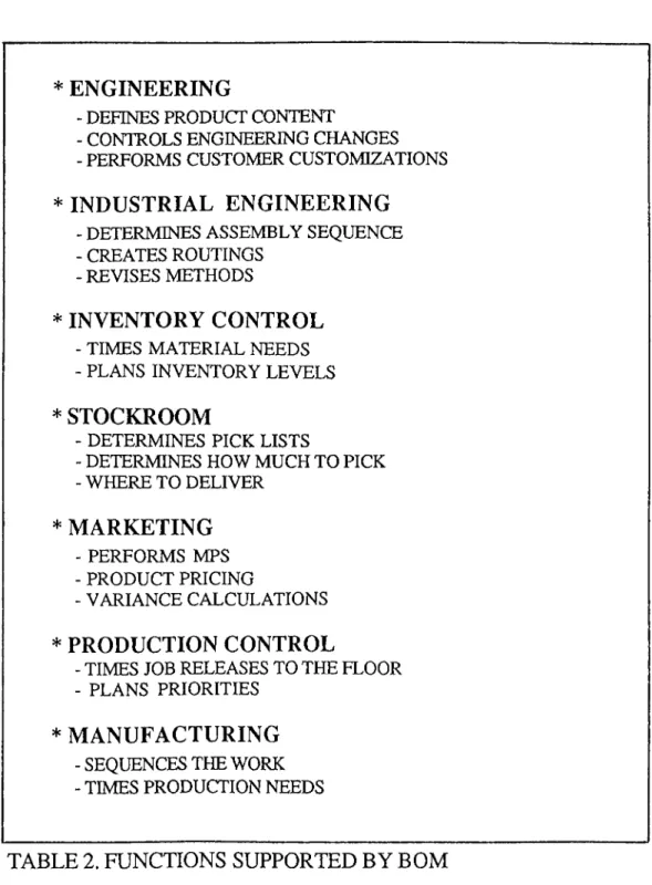
Today, there exists many different BOM versions such as single level, indented, summary, costed, modular, etc. The functions supported by BOMs within an integrated manufacturing environment are given in Table 2.
* ENGINEERING
- DEFINES PRODUCT CONTENT
- CONTROLS ENGINEERING CHANGES - PERFORMS CUSTOMER CUSTOMIZATIONS
* INDUSTRIAL ENGINEERING
- DETERMINES ASSEMBLY SEQUENCE - CREATES ROUTINGS
- REVISES METHODS
* INVENTORY CONTROL
- TIMES MATERIAL NEEDS - PLANS INVENTORY LEVELS
* STOCKROOM
- DETERMINES PICK LISTS
- DETERMINES HOW MUCH TO PICK -WHERETO DELIVER * MARKETING - PERFORMS MPS - PRODUCT PRICING - VARIANCE CALCULATIONS * PRODUCTION CONTROL
- TIMES JOB RELEASES TO THE FLOOR - PLANS PRIORITIES
* MANUFACTURING
- SEQUENCES THE WORK - TIMES PRODUCTION NEEDS
TABLE 2. FUNCTIONS SUPPORTED BY BOM
INVENTORY RECORDS : These records contain the amount of available stock at various locations within a stockroom or within multiple stockrooms which are used in the n e ttin g process. Maintanence is performed by updating these records. Since high accuracy is required for successful MRP operation, cycle counting programs are established as well as abc classifications.
These records also contain certain Inventory policies like safety stock, lead times, lot sizes, order multiples, shelf lives which play very significant roles in the MRP system.
Inventory Replenishment is another concept that affect these records and thus MRP netting process. Generally there exists four types of replenishments;
1) Manufacturing order 2) Firmed planned order 3) Purchase order
4) Purchase requisition
-Used for make parts -Used for make parts -Used for buy parts -Used for buy parts
M ASTER SCH ED U LE: It is a statement of what the company plans to manufacture for a given period of time. It is the planned build schedule, by quantity and date, for top level item which allows the system to derive lower level requirements with the help of BOMs.
2.2 KEY MRP-II MODULES
MASTER PRODUCTION SCHEDULING: This module drives the MRP and is the key input to the MRP process. This module takes into account the sales forecasts as well as special considerations such as backlog, availability of material, availability of capacity, company goals etc. For successful MRP-II operation MPS should be realistic in terms of the goals it sets ‘ and must not be a wish list of desirable production.
Naturally the accuracy of MPS varies throughout the planning horizon. The data that covers the near term would be more accurate than data out in planning horizon.
The difference between the MPS module and the MRP process is that demand will only propogate from the scheduled MPS and not from the projected requirements. This implies that the MPS will not influence production or purchasing without the intervention o f the master scheduler. [47]
ROUGH CUT CAPACITY PLANNING: This module performs a relatively quick check on a few key resources required to implement the master schedule, to assure its feasibility from a capacity of view. Thus, the MRP and RCCP are developed interactively.
In RCCP, a bill of resources is related to each of the master scheduled items. This bill of resource describes the capacity of various key elements like people, machines, floor space etc. required to produce one unit of the product. No consideration is given to component availability or capacity requirements but the plan is entirely driven by MPS against the bill of resource. As a result this technique determines the impact of production plan on key (aggregate) resources, and reveals whether the MPS is feasible or not from a broad point of view.
CAPACITY REQUIREMENTS PLANNING: When MRP system operates it generates p l a n n e d orders for both manufacturing and purchasing based on planned lead times for manufactured and purchased parts, ignoring all capacity constraints.
However, these MRP outputs can be utilized also to plan capacity. This is done simply by exploding planned manufacturing orders against the routings specified in the production activity control system. The result is a report containing required hours, available hours and +/- deviations listed for each work center.
One drawback of CRP system is that it can only be performed after each MRP run and thus does not facilitate interactive planning which is possible in RCCP.
2.3. THE M A N U FA C TU R IN G DATA BA SE:
It is clear from the discussion so far that the MRP system relies and operates on a large number of data. This essential data is kept within the production data base.
The information flow in MRP-II and the entire integrated MRP-II system is given in F ig.5 and 6 respectively. This integrated system uses mainly the following six catagories of data:
1. The Master Part Information 2. Full Inventory Information 3. BOM Information
4. Routing Information 5. Work Center Information 6. Tooling Information
The definitions and application areas of these data have been examined previously. Thus the following section will discuss only their contents.
The master part information contain data on each item controlled by the MRP system. Typically, it is sufficient to define each part in terms of the data given in Table 3. This data is termed as static data since they are usually altered by the user.
The second data source is the full inventory status in which data is constantly changed and updated by the system. This type of data is called dynamic data. Table 4. shows the full inventory status fields.
SALES FORECAST
V/HAT WAS SHIPPED ?
Fig.5 INFORMATION FLOW IN MRP II
RESOURCE FLOW MANAGEMENT PERFORMANCE PLANNING AUDIT TSSTRBDTSr MATERIAL MANAGEMENT RECEIVING INSPECnON INSTAlIÂtlÖN HELD SERVICE COrTTROL JUST IN TIME MATERIAL CONTROL
BAR CODING & OCR TRACKING RESOURCE PU\MNING PRODUCnON PLANNING ROUGH CUT CAPACTTY PLANNING r MASTER PRODUCTION SCHEDUUNG C" ROUTING^ J C BIUL OF A MATERIAL J VÎAT__
i r
REQUREMENTS PUNNING DETAILED ^ CAPACriY PLANNING ORDER RELEASEr
SHOP FLOOR CONTROLcz:
REQUREMENT RECORDS MATERIAL AND CAPACITY PLANS PURCHASING Ve n d o rfo llo v^^-uf i SYSTEM DEI/tAND MANAGEME^JT FRONT END MARKETING SALES INFORMATION COST ACCOUrmriG INFORMATION INVENTORY)
VOICE RECOGNmONi VISION SYSTEMENGINE INTEGRATED DATA ACQUISITION COÎ.IPONENT SUB ASSEMBLY BACK END INTERACTIVE HUM N CONTROL AUTOMATED PICK & CHIP
PORTABLE 1 CAO/CAM ROBOTIC FLEXIBLE MACHINE BARCO DE 1 CNC DESIGN ASSEM BLY _____ s is ie M _____MANUFACTURIN G INTERFACE
Fig.6 INFORMATION FLOW IN AN INTEGRATED MRP II SYSTEM
* PART NUMBER * PART DESCRIPTION
- MUST BE UNIQUE
* UNIT OF MEASURE - MANDATORY
*LOT SIZE POLICY
* LOT SIZE QUANTITY - IF RELEVANT
♦SAFETY FACTOR - IF RELEVANT
♦BURDEN FACTOR ♦ LEAD TIME
- IF RELEVANT
♦SOURCE CODE - MANDATORY
♦ LOCATION - IF RELEVANT
♦ ACCOUNT NUMBER - IF RELEVANT
♦MPS CODE - MANDATORY
♦ STANDARD COST - IF RELEVANT
♦ MATERIAL COST - IF RELEVANT
♦LABOR COST - IF RELEVANT
♦ OVERHEAD COST - IF RELEVANT
TABLE 3. MASTER PART INFORMATION FIELDS [3]
♦ CURRENT INVENTORY -LOCATION SORTED
♦ ALLOCATIONS
♦OPEN ORDERS - BY TIME BUCKET
♦ GROSS REQUIREMENTS -B Y TIME BUCKET
♦ NET REQUIREMENTS -B Y TIME BUCKET
♦ PLANNED ORDER RELEASES -B Y TIME BUCKET
TABLE 4. FULL INVENTORY INFORMATION FIELDS [3]
The BOM information defines the structure of the product. The data is stored in a manner that is suitable to support various BOM formats like indented, summary, single level etc. The BOM information fields are given in Table 5.
* PARENT PART NUMBER
* FOR EACH CHELD
- COMPONENT PART NUMBER - QUANTITY PER ASSEMBLY
- EFFECTIVITY DATES - IF REQUIRED
TABLE 5. BOM INFORMATION FIELDS [3]
Routing information defines the manufacturing and/or assembly operations that are followed in order to produce a product. The data contained within this section is usually technical engineering data that must be collected from the shop floor employing special methods. The routing information fields are given in Table 6.
* PART NUMBER - MUST BE MANUFACTURED
PART * FOR EACH OPERATION
- OPERATION NUMBER - OPERATION DESCRIPTION - WORK CENTER NUMBER
- ALTERNATE OPERATION - IF EXISTS - REFERENCE INFORMATION
- SET-UP TIME - LABOR TIME
- i.e.: TOOLS USED
TABLE 6. ROUTING INFORMATION FIELDS [3]
The work center information is primarily used for capacity planning purposes. It provides data on every work center within the company which defines the work center as a resource. A typical work center record contains the data given in Table 7.
* WORK CENTER NUMBER * WORK CENTER DESCRIPTION * AVAILABLE CAPACITY * UNITS OF CAPACITY * AVERAGE QUEUE TIME * WORK CENTER COSTS
-UNIT LABOR COST - UNIT MACfflNE COST - UNIT OVERHEAD COST
TABLE 7. WORK CENTER INFORMATION FIELDS [3]
Tooling information provides data on tools which are available and associated with particular operations and work centers. This information provides a mechanism by which the company can monitor its critical tools and plan their best utilization. The fields of tooling information are given in Table 8.
* TOOL NUMBER * TOOL DESCRIPTION
* TOOL LOCATION IN STORES * TOOL STATUS
♦TOOL LIFE
* ALTERNATIVE TOOL - IF AVAILABLE
TABLE 8. TOOLING INFORMATION FIELDS [3]
The data structures presented above mainly attempt to provide a general insight to the theory in order to be able to relate it to the contents of this thesis study.
2.4. THE STATUS OF M RP II SYSTEM S
As it can be seen from the previous discussion. Manufacturing Resource Planning systems operate on a deceptively simple logic employing a complex network of integrated subsystems. Thus, although there are some exceptions that use custom made systems, most companies prefer using professional MRP II softwares to implement.
Even with a professional software on hand, implementation is a true challenge due to the uniqueness of each company which bring along adoptation issues. Therefore the effectiveness of an MRP II system depend on the compeny's way of using it.
Although the pragmatics of operating an MRP system were first established by Orlicky [38] its enhancement and detailed studies were later performed by Wight [47]. The issue of the level of utilization of MRP's capabilities were first attacked by Wight in his work "MRP II: Unlocking America's Secret Potential". In this work, Wight developed an evaluation scheme that consists of 25 technical questions whose answers lead to the classification of users between classes A to D, The basics of this evaluation scheme contains the following criteria :
- Planning buckets should be no longer than one week.
- Planning frequency must be at least one week. - Shortage lists must be eliminated.
- Delivery performance for vendors, production and MPS should be at least 95 %.
- Performance improvements in at least two of the topics listed below should be noted :
- INVENTORY - PRODUCTIVITY - CUSTOMER SERVICE
The surveys performed using the criteria listed above indicate certain problems in MRP II implementations:
According to Anderson et.al, (1982) and Schroeder et.al (1981) only 9.5% of all MRP users consider themselves class A and 61.3 consider themselves class C or D.
Anderson et.al. found that only 52.2% of MRP II users use computerized MPS. Laforge (1986) reported 42%. CRP utilization is even lower than computerized MPS which was reported as 37.7% by Anderson et.al. and 42% by Laforge.
РАС was only implemented by 30.5% according to Anderson et.al. and 52% by Laforge.
On the other hand some improvements resulting from MRP II implementations were also reported by Anderson et.al.
Average inventory performence improved from 3.2 to 4.3 turns.
Average delivery times fell from 71.4 to 58.9 hours that indicate a 18% improvement.
Average delivery performence rose from 61.4% to 76.6% .
Average number of expeditors fell from 10.1 to 6.5. As a result, it can be said that MRP II is a viable approach with a proven track record with certain drawbacks. Unfortunately, proven viability is not sufficient to succeed in all MRP II applications. The following section discusses the applicability of MRP II in electronics industry.
2.5. A PPLIC A BIL IT Y OF M RP II
Although prerequisites and assumptions of MRP II systems have been previously discussed they do not present a good criteria for applicability. The existence of required conditions depend more on the management practice rather than the type of business in question. Thomas Wallace [44] has listed the manufacturing environments in which MRP II had been successfully implemented as follows :
1. Conventional manufacturing (fabrication, assembly)
2. Fabrication only. 3. Assembly only.
4. Repetitive manufacturing. 5. Process manufacturing. 6. High speed manufacturing. 7. Low speed manufacturing. 8. M ake-to-stock 9. M ake-to-order 10. Engineer-to-order 11. Complex product. 12. Simple product. 13. Job shop. 14. Flow shop.
15. Manufacturers with distribution networks.
It is easy to notice the wide scope of application potential of MRP II from the items listed above. Therefore, it is fair to deduct that electronics industry lies within the scope of MRP II applications simply due to the discrete conventional manufacturing environment it operates in. Evenmore, electronics industry obeys the main prerequisites and assumptions of MRP as follows:
-Discrete manufacturing environment. -Modular product structure.
-High number of components.
-Product structure expressed in terms of BOMs. -Inventory investment levels dominant in products
cost.
-Nonuniform, discrete product demand.
In the light of the characteristics listed above electronics industry is prone to MRP II application where stock replenishment techniques often yield disappointing results.
2.6 THE SOFTWARE(i)
The main driving force in an MRP II implementation is the software. Each software package operates on the basic logic of MRP II but has its own additional characteristics and methods that need to be considered to succeed in implementation. The software used for this implementation is the MANMAN^ ^ ' ^ Management Inform ation System developed for Digital VAX computer systems.
MANMAN is an integrated system of software products that addresses the manufacturing, marketing, financial and managerial reporting needs of a company. The system has been widely implemented by more than 2000 manufacturing companies all around the world. The modular system is designed to streamline manufacturing operations which will allow more efficient business m anagem ent.
MANMAN's system-wide features such as online inquiry, interactive data entry, real time updating and built-in business variables allow it to be adopted uniquely to each manufacturing company.
The modules of MANMAN are given in Fig.7 and listed below. The first five modules are called the core five since they form the basis of the MRP II system.
(1) THIS SECTION HEAVILY DRAWS UPON [29], [30], [31], [32]. (2) MANMAN IS THE TRADEMARK OF ASK COMPUTER SYSTEMS
Fig.7 MANMAN SOFTWARE MODULES
1. MANMANIMFG 2. MANMANIOMAR 3. MANMANIGL 4. MANMANIAP 5. DECISIONMAKER 6. MANMAN/FA 7. MANMAN/REPETITIVE 8. MANMAN/TRACKER 9. MANMAN/ENGINEER 10. MANMAN/BARSCAN 11. MANMAN/PROJECTS 12. MANMAN/SERVICEMAN 13. MANMAN/DATAPORT 14. PLANMAN/MFG 15. PLANMAN/GL
The work discussed within this thesis deals mainly with the implementation of the manufacturing management (MFG) module. Thus, characteristics of only this module will be examined in detail in the following section.
2.6.1 M ANM AN/M FG
M A N M A N / M F G streamlines the manufacturing process by giving everyone the information needed to plan priorities, respond to production changes, meet delivery schedules and keep labor and material costs under control. On the other hand, the system entitles the production planners to access the vital inventory and priority planning information in order to create realistic schedules that inturn lead to better vendor delivery and work order scheduling. The MFG module contains all the functional submodules (Fig. 8) necessary to plan and control priorities and capacities, track shop floor activities while providing cost accounting capabilities. When integrated with other MANMAN products (Fig. 9) the system forms a comprehensive management information system.
Fig.9 MANMAN/MFG SYSTEM INTEGRATION
Fig.8 MANMAN/MFG SUBMODULES
Each MFG submodule carries out a specific function that is vital for effective production management. The material control module includes the following main functions that pertain to inventory (Fig. 10) :
* Adding and maintaining parts
* Adding and maintaining inventory locations * M aintaining accurate inventory counts
* M oving parts in and out o f stock on work orders, purchase orders and sales orders
* Monitoring the current status o f inventory
These main functions possess the following capabilities :
* Performing on-line transactions o f issu es and receipts of part to and from ;
- sto c k
- cu sto m ers/fin ish ed goods - w o r k - in - p r o c e s s
- rec eiv in g in sp ection - repetitive assem bly lines
* Including MRP nettable and nonnettable location s for stock in g parts.
* A llow ing either single or multiple inventory locations per part with the option o f lot/serial number tracking.
* P roviding ex ten siv e reporting o f o b so lete and ex cess in v e n t o r y .
* Performing ABC analysis based on :
- part usage - unit cost
- projected usage
- current q u a n tity -on -h a n d
* Maintains a transaction log as audit trial o f all on-hand inventory transactions and standard costs changes.
* Cycle counts both sides and wip locations based on ABC analysis and custom counting frequency.
* A llocates materials to work orders.
* Generates single or multiple kit lists and/or kitting labels. * A llow s kitting by exception.
* Checks material availability prior to kitting and reports s h o r ta g e s .
* P rocesses reciepts and returns o f stock for com plete purchase orders or individual line items.
2 < ОС (J < Q
1
l i -< ce Ш s 0 U-ξ Z < 2 Z < 2Ü-* Monitors delivery status.
* Provides interplant transfer functionality.
The second sub-module is the engineering data control module which enables the user to design and produce the product employing the best methods that are available. This function is established through the following engineering features ;
* M aintaining a ssem b ly -co m p o n en t rela tio n sh ip for regular,planning and phantom (blow-through) bills up to
25 levels.
* Providing powerfull maintanence capabilities : -delete a part on all BOMs.
-copy a BOM.
-perform mass changes.
* Providing on-line and printed access to costed, indented and summarized bills.
* Providing various where-used ? reports.
* Implementing engineering changes and revision levels through effectivity dates and historical reporting.
* Maintaining a record for each work center that details : -description of work center.
-hourly set up and labor/machine rates. -overhead rates.
-capacity hours per day. -crew size.
-work center type.
The third functional module is the product costing module which determines the standard costs for each part, including cost of material, labor, overhead and outside processing for each level of assembly.
Determining the standard cost of a product is important because the total cost of building an assembly determines that products final selling price. In addition, standard costs are used for inventory valuation and are taken as basis in varience calculations which are performed by the software to calculate deviations from the standard values. This module encompasses the following functions:
* Providing complete cost roll-up capabilitiy for all or individual parts.
* Revaluation o f stores and wip inventory whenever
standard costs change.
* Providing ability to develope next year's costs without impacting current standard costs.
* Producing reports on :
-costed single level or indented BOMs.
-costed routings.
34
The master planning module is the fourth module that covers the ability to develop and implement the production schedule. The sequence of events within a factory starts with the development of a business plan which reflects the general company policy. Next, the production plan is developed to reflect what manufacturing is capable of producing based on the forecasts of the sales department. This plan outlines the general trend of production in terms of broad categories of products or product families. This plan is only finalized when both sales and manufacturing have approved it. From this point on the master scheduler has the responsibility of updating and maintaining this schedule. In MANMAN/MFG the master planning function can be performed using the following methods:
1. Single level MPS ; uses no planning bills.
2. Single level MPS ; uses planning bills for forecasting p u r p o se s.
3. Product family MPS ; uses family links to create production forecasts for MPS parts.
4. Configurable parts MPS.
The fourth method varies from the standard MPS methods and it is actually a special feature of MANMAN which brings along a fairly simpler approach to scheduling of product families with many options. The pilot project discussed within the scope of this thesis deals with configurable product MPS and therefore this technique is explained in more detail in the following section.
The configurable part MPS technique is a two level MPS method which uses both the top level MPS and lower level reporting features. This technique uses the following sequence of events:
STEP 1: ADD THE PRODUCT STRUCTURE FOR THE CONHCURABLE PART
STEP 2: ADD ALL FORECASTS
STEPS: USE A UTILITY TO CHECK THE FORECASTS FOR THE CONHGURABLE PART
STEP 4: ADD THE PRODUCTION PLAN FOR THE CONHGURABLE PART
STEP 5: ENTER SALES ORDERS FOR THE CONHGURABLE PART STEP 6: RUN TOP LEVEL MPS TO SEE SUPPLY AND DEMAND
FOR CONHGURABLE PART
STEP 7: RUN MPS TO SEE SUPPLY AND DEMEND FOR LOWER LEVEL MPS PARTS
STEP 8: RUN TEMPORARY PARTS REPORT
STEP 9: ADD FIRM PLANNED FINAL ASSEMBLY WORK ORDERS FOR TEMPORARY PARTS AND ADD RELEASED FINAL ASSEMBLY WORK ORDERS.
The BOM for a configurable product includes all possible features available for that product family. These options and/or choices are then selected by the user to form a specific end product. Each such selection is designated and tracked by a temporary part number within the system. The configurable product BOM are identified by order policy codes (OPC) 1 and 8. OPC 8 shows the product family whereas OPC 7 denotes each configurable option. A possible product structure for a configurable part is shown in F ig .ll.
When a BOM for a configurable product is added to the system, the system allows the user to select both mandatory and optional features. A feature, whether mandatory or not, always involves a selection between options. Features and components are configured during sales order entery (Fig. 12). Obviously the system requires a product to have a modular structure in order for it to be configurable. There the prime must for any configurable product application is modularity.
The master planning module contains the following features :
* Strategic planning capability via one or two level MPS. * A llow ing simulation o f future delivery o f product fam ilies
and critical items as well as one or groups o f parts.
* C onsideration o f fo reca sts, sales orders, independent demands and all other dependent demands in its c a lc u la tio n s
* Employing demand and planning time fences.
CAMERA O P C : 8 OPTICAL O P C : 7 WINDER O P C : 0-4 CAMERA BODY O P C : 7 FLASH O P C : 0-4 LENS MOUNT O P C : 0-4 LENSES O P C : 7 CHROME O P C : 0-4 BLACK O P C : 0-4
SOMM LENS 150 MM LENS 35-70 MM LENS
O P C : 0-4 O P C : 0-4 O P C : 0-4
F ig .ll CONFIGURABLE PRODUCT STRUCTURE
CAMERA X
OPC : 8
LENS MOUNT
150 MM LENS
CHROME BODY
FLASH
Fig.l2 A CONFIGURED PRODUCT
* Reporting, by w eekly buckets, to show parts' projected availability and available-to-prom ise status.
* Pegging requirements to the source o f demand.
* Producing warning and exception m essages for proposed changes to the master schedule.
* A llow ing critical resource analysis.
* Comparison o f MPS to the available critical resources.
The fifth module is the material and capacity p l a n n i n g module which determines what needs to be ordered and when to meet all demand while keeping the inventory level as low as possible and how to attain a realistic balance between an order's capacity requirements and actual shop capacity. This function is the heart of the system that provides the information needed for planners to release purchase and work order at the right time with the right quantities. This module comprises the following functions :
* Using MPS as an input to the MRP p r o c e s s .
* Maintaining all information used by MRP and CRP. * Running MRP on a regular basis.
* Reacting to MRP.
* Running capacity planning reports.
The material and capacity planning sequence of events are given in Fig. 13. Running through this sequence the system performs the following main actions :
Exploding assem blies and sub-assem blies into component r e q u ir e m e n ts .
A llow ing a bucketless, user defined planning horizon. Recommendation o f purchase and work order quantities and dates based on production and demand schedules. Recommendation of due date changes ;
-pull ups -push outs - c a n c e lla t io n s
Pegging MRP requirements to the next level up to the end item level.
A llow in g lot-for-lot inventory planning.
A llow in g the user to em ploy any com bination o f the follow ing order modifiers ;
-safety stock
-number o f days supply
-minimum order quantity, etc.
—
CURRENT PRODUCT LEAD TIMES DEPENDENT INVENTORY STRUCTURE SOURCE CODES.OPC DEMAND
SCHEDULED RECIEPTS
PROJECTED
*■ SUPPLY INFORMATIONPART
DEM/
IMFORN ... kNDlATION INDEPENDENT DEIvlAND MRP OPEN WORK ORDERS OPERATION HOURS RELEASE FIRM PUNNED ORDER RESCHEDULE PURCHASE ORDER RESCHEDULE PURCHASE REQUISITIONS RESCHEDULE WORK ORDER CRP REACTING TO MRP CANCEL PURCHASE ORDERS V/ORK CENTER CAPACITIES ADD PURCHASE ORDERS ADD RELEASED WORK ORDERS CANCEL WORK ORDERS ¡CREATE SUGGESTED PURCHASE REQUISITIONS ADD/FIRM UP PURCHASE REQUISITIONS
Fig.l3 MATERIAL and CAPACITY PLANNING SEQUENCE OF EVENTS
* Consideration of part and component yield in the calculation of material requirements.
* Recommendation of dates based on user defined
manufacturing calender.
* Supporting various types of work orders; - firm planned
- rew ork - routable - subcontracted
* Reporting MRP results in various formats; - v e r tic a l
- h o rizo n ta l - by part - costed
* Maintaining both machine and labor capacity by work c e n te r .
* Producing work center capacity reports indicating weekly
load at each work center on open and planned jobs.
* Reporting, percent utilization and available capacity by work center weekly either as summary or detail.
The sixth module is the purchasing module which is closely tied with the material and capacity planning and material control modules. This module performs the following functions :
* Generation and usage o f various types o f purchase orders; - regular (inventory, m iscallan eou s)
- expensed - su b c o n tr a c te d - b la n k e t
* Using both nettable and nonnettable purchase orders (PO). * S u p p ortin g foriegn cu rrency p u rch ase orders and
automatically converting foreign currency to base.
* Maintaining two different units o f measure (stocking and p u rch a sin g ) and p erfo rm in g a u to m a tic c o n v e r s io n between the two.
* R eporting PO com m itm ents by date, vendor or part n u m b e r .
* A n a ly z in g v en d o r p e rfo rm a n ce and m a in ta in in g
approved vendor lists.
* Accomodating blanket POs o f all types that enable formal vendor agreements by specifying ;
- part number - q u a n tity
- negotiated price - expiration date
The seventh module is the shop f lo o r control module which controls the work-in-process (WIP) by moving parts through the production and by monitoring the overall flow of work orders through work centers. This function supports the following features :
* Tracking all information on production from the time a work order is entered into the system until it is intentionally deleted.
* Monitoring and recording all work order related activities including cost for material, labor, fixed and variable overhead and outside processing throughout production. * A llow ing independent standard set-up, run and transit
rates to be tracked at each routing operation. * Using various scheduling methods such as;
- backward sch ed u lin g - forward sch ed u lin g - w indow scheduling
* Providing autom atic resch ed u ling o f operations when order dates, quantities or prior operation dates change. * A llow ing deviations from standard routings according to
specific customer needs.
* Reports dispatch lists by work center or work orders.
* Reports labor distribution by em ployee, operation, work center and work orders.
The eighth functional unit is the cost accounting module that is used to monitor and control costs in manufacturing environment. It is the finance link that is added to the standard MRP practice. This module establishes the following :
* C alculation o f absorbed m aterial, labor and ou tsid e p rocessin g overheads.
* Maintaining an audit trail o f material and labor currency transactions from material and shop floor control modules. * Providing both actual and standard job costing during the
life o f the job.
* Reporting labor distribution o f costs for direct, indirect and idle hours.
* Producing reports on ;
- inventory and WIP cost evaluation. - standard cost inventory
- purchase price variences
* Evaluating scrap based on the percentage o f the last com pleted operation.
* R e p o r tin g WIP v a r ie n c e s fo r m a teria l u s a g e , configuration, labor rate, method change and lot size. * Reporting cost detail and variences on open and closed
work orders.
* Allowing multistage work order close ; - material only
- material and labor - a c c o u n t in g
The last submodule is the p h y s i c a l inventory module that provides the most accurate and least controversial means of assessing inventory value, particularly for tax reporting. This module assists in performing complete stores physical inventory by :
* Generating inventory tags.
* Providing variences and m issing tag reports.
* A llow in g recount, reconciliation , sim ulation cap ab ilities prior to performing final updates.
As a conclusion all nine submodules of the MFG package can be said to form an integrated system that is overly qualified to perform all attributes of an MRP II system.
2 . 7 . PREVIOUS WORK
The research conducted on MRP, MRP II and implementation of these methods is quite detailed and comprehensive. Therefore it is important to select the sources that will directly contribute towards the formation of the knowledge that is necessary to understand tne MRP II theory and its implementation methods. Once the knowledge the knowledge about the theory and past experience is collected they should be aggregated and applied to the particular case on hand by developing a specific approach. Thus, this section will briefly explain the literature referred throughout all phases of this study.
The sources used to guide this study from a theoretical aspect are [3], [4], [16], [38], [42] and [47], Similarly, the implementation oriented sources are [5], [6], [7], [8], [10], [12], [15], [18], [20], [21], [35], [38], [44] and [47].
The fundamental work on MRP is by Orlicky [38], in which he provides the history and development of MRP, its basic features and the t heor y in a clear and perceptable manner. The comparison of MRP with order point techniques including advantages, disadvantages and applicability of the two approaches is discussed in detail. In addition, the entire logic behind MRP technique, its main data elements, interpretation of system outputs, main system design issues are explained providing insight to the philosophy of the approach.
Similarly, another useful elementary guide is by Browne, Harhen and Shivnan [3] in which they present all the basics of most common contemporary production management systems namely MRP, JIT and OPT. The book states the increasing emphasis being placed on c o m p u te r integrated manufacturing (CIM) as a direct consequence of the competition among industrial firms by presenting an overview of CIM. The role of production management within a discrete manufacturing environment is analyzed for three modes of operation; job shop, batch and mass production. Moving on from that point, the production management system (PMS) is identified as the core of CIM. The connecting link between higher planning methods of PMS and the execution level is described as the p r o d u c t i o n activity control system. Following these general conceptual analysis, the three important strategies of production management is discussed in detail. The first approach is MRP and MRP II. Their background, evolution, attributes and mechanics of operation is defined and supported by examples. Then the use of MRP and planning methods within this system is discussed. A similar analysis is performed for the remaining two approaches; JIT and OPT.
Buffa and Taubert's work [4] directly empasizes the idea of "integration" in production management area where top down manufacturing planning systems are discussed. The basic elements of production management techniques are provided incostituting practical background to complex manufacturing environments.
![TABLE 3. MASTER PART INFORMATION FIELDS [3]](https://thumb-eu.123doks.com/thumbv2/9libnet/5664383.113265/32.956.169.783.80.694/table-master-part-information-fields.webp)
![TABLE 5. BOM INFORMATION FIELDS [3]](https://thumb-eu.123doks.com/thumbv2/9libnet/5664383.113265/33.956.189.770.751.1013/table-bom-information-fields.webp)
![TABLE 7. WORK CENTER INFORMATION FIELDS [3]](https://thumb-eu.123doks.com/thumbv2/9libnet/5664383.113265/34.956.180.780.261.598/table-work-center-information-fields.webp)
