phys. stat. sol. (b) 244, No. 4, 1192 – 1196 (2007) / DOI 10.1002/pssb.200674505
Radiation properties of a split ring resonator
and monopole composite
Kamil Boratay Alici* and Ekmel Özbay
Nanotechnology Research Center, Department of Physics, Department of Electrical and Electronics Engineering, Bilkent, 06800 Ankara, Turkey
Received 19 September 2006, revised 20 November 2006, accepted 20 December 2006 Published online 22 March 2007
PACS 41.20.Jb, 84.40.Az, 84.40.Ba
We studied the far field radiation properties of a new resonator antenna composed of split ring resonators (SRRs) and a monopole. It is shown that the antenna size at the operation frequency (3.52 GHz) is ap-proximately one tenth of the free space wavelength (λ/10). Moreover, increasing the number of SRRs yields steerability properties. These achievements provide a way to create rather small steerable resonant antennas.
© 2007 WILEY-VCH Verlag GmbH & Co. KGaA, Weinheim
One of the most common elements of metamaterials, which was introduced by Pendry et al. in 1999, is the split ring resonator (SRR) [1]. SRR is an nonmagnetic conducting unit, in which and its periodic array yields negative effective magnetic permeability with an enhanced magnitude when the frequency of the incident electromagnetic field is close to the SRR resonance frequency. The resonance frequency of the SRR depends on its geometrical parameters [2, 3]. The structure can show resonant behavior at frequencies that are much larger than its size. Experimental demonstration of this structure at microwave frequencies has been achieved by many groups [2 – 7].
The application of metamaterials to increase antenna performance is of great interest. It was shown that introducing metamaterials could enhance the radiated power of the antenna [8]. Moreover, negative magnetic permeability materials are a candidate for obtaining properties such as an electrically small antenna size [9 – 14], high directivity [15, 16], and tunable operational frequency [13, 17]. Furthermore, by utilizing a combination of right handed (RH) and left handed (LH) materials in a composite (CRLH) transmission line, a backward to forward scanning capability is obtained [18].
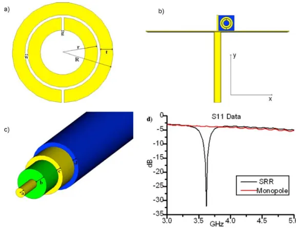
Antennas composed of single negative materials that resonantly couple to external radiation was in-vented by Isaacs [19]. Even if the radiation wavelength is much larger than the antenna size, the antenna is sensitive to radiation due to the resonant coupling. By feeding such a resonator one can obtain an elec-trically small antenna when operating at microwave frequencies. This is the basic idea of our study. We used the SRR depicted in Fig. 1. Its geometrical parameters are R = 3.6 mm, r = 2.5 mm, g = w = 0.2 mm, t = 0.9 mm. The substrate is the standard FR-4 material with a thickness of 1.6 mm, relative permittivity 3.85 at 4 GHz, and a loss tangent 0.008 at 3 GHz. The SRR is fabricated by etching the deposited 30 µm thick copper.
We excited the SRR by using a monopole antenna Fig. 1b. A monopole antenna is composed of a coaxial cable, ground plane, and radiating wire part. We used an SSI 0413 coaxial cable with an inner wire radius (a) 0.49 mm, Teflon thickness (b) 1.08 mm, shield thickness (c) 0.48 mm, and insulator coat-ing thickness (d) 0.48 mm (Fig. 1c). The Teflon dielectric constant was 2.2, in which the cable can
phys. stat. sol. (b) 244, No. 4 (2007) 1193
Paper
Fig. 1 (online colour at: www.pss-b.com) a) Schematics of a split ring resonator (SRR). b) Schematics of the SRR inserted monopole antenna. c) Schematics of the coaxial cable. d) Measured S11 for the monopole source and monopole SRR composite.
transmit the TEM mode waves up to 65 GHz safely. The ground plane material is aluminum and is con-nected to the shield by a conducting paste. It is 0.5 mm thick and has a square shape with an edge length that is equal to the free space wavelength. The operation frequency was 3.52 GHz, which was deter-mined by considering the SRR’s geometrical parameters. The corresponding free space wavelength (λ) was 85.17 mm. The length of the wire above the ground plane was 8.32 mm and for the monopole an-tenna this length corresponds to a quarter of the operation wavelength. Thus this monopole anan-tenna was working efficiently when feed wavelength was 33.28 mm and feed frequency was 7.8 GHz. Therefore, the SRR resonance frequency is smaller than the monopole operation frequency. The SRR is positioned rather close to the radiating wire part of the monopole antenna.
At the operation frequency, 3.52 GHz, the wire part and SRR behave as a composite radiating struc-ture. The characteristic impedance of the coaxial cable and wire SRR composite becomes very close, in which the surface currents on the SRR increase an order of magnitude and the structure starts to radiate efficiently.
For the theoretical calculations, we simulated the structure via the commercial program: Computer Simulation Technology Microwave Studio (CST MWS). There was a considerable change at the S11 and at the surface current at the operation frequency with respect to a nonresonant frequency. S11 reduced to – 30 dB from – 3 dB and the surface current increased from 90 A/m to 2460 A/m. For the experimental demonstration, we used an HP8510C Network Analyzer. After a full two port calibration we measured the monopole antenna S11 in order to determine its efficient operation frequency, which is 7.8 GHz. Subsequently, we measured the S11 parameter between 3 GHz and 5 GHz (Fig. 1d). We observed that the composite to be a – 32 dB S11 value.
1194 K. B. Alici and E. Özbay: Radiation properties of a SRR and monopole composite
Fig. 2 (online colour at: www.pss-b.com) Far field pattern of the SRR monopole composite: a) 3D view, c) E plane (x–y plane), d) H plane (y–z plane). b) Far field pattern of the monopole (3D view).
We also obtained the far field radiation patterns of the structure by using the simulation results. The structure radiates similar to a single element patch antenna. The 3D far field view and corresponding E plane and H plane patterns are shown in Fig. 2. Main lobe direction was 115°, and the directivity is 6.53 dBi. In order to show that the effect is purely due to the magnetic resonance of the SRR, we also reveal the closed split ring resonator (CRR) results. CRR has the same parameters as SRR but the splits are closed. We consider the same planes as the SRR monopole composite. The CRR insertion does not have an effect on the monopole, on the other hand, SRR insertion entirely changes the antenna character-istics, such as the radiation pattern.
In order to estimate the radiation efficiency of the antennas we performed the absolute-gain measure-ments [20]. The gain of the SRR monopole composite antenna is found by comparing it with a standard horn antenna. Two-antenna method is applied and the gain of the 1 SRR monopole composite is found as 2.35 at 3.62 GHz. At this frequency we had minimum insertion loss (S11). The far field radiation pattern cuts are measured by the aid of the horn receiver antenna. The half-power beamwidths of the E and H plane patterns implied the directivity of the antenna as 5.48 dBi [20]. And finally we estimated the effi-
phys. stat. sol. (b) 244, No. 4 (2007) 1195
Paper
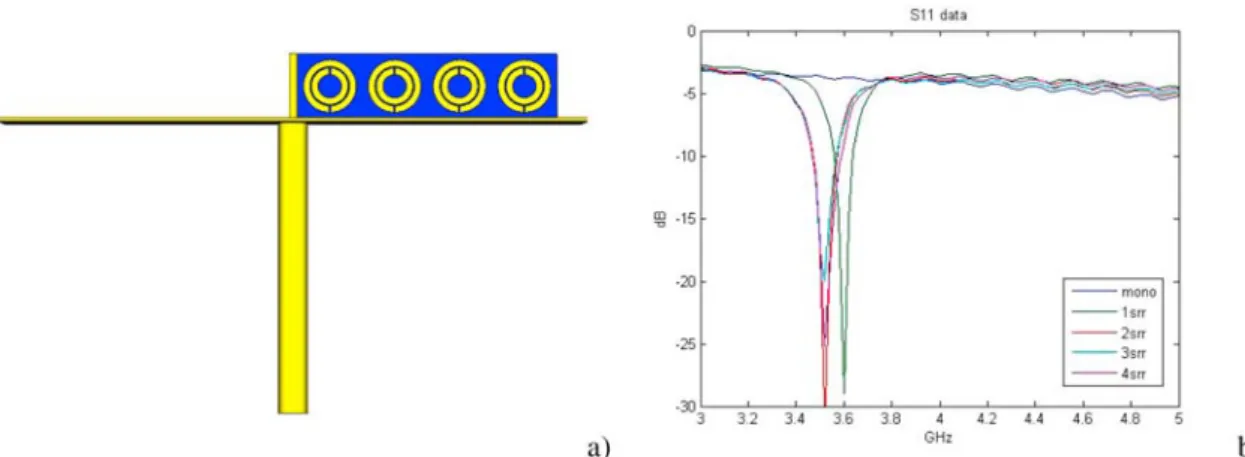
Fig. 3 (online colour at: www.pss-b.com) Schematics of 3 SRRs monopole composite. b) Measured S11 data for several number of SRRs and monopole.
ciency as 42.88%. For the multi SRR cases measured gains were almost the same as 1 SRR case. The simulations of the multi SRR cases show that directivity of these antennas is almost the same as the 1 SRR case also. Therefore we can safely conclude that efficiencies of the multi SRR and 1 SRR anten-nas have similar values. These results indicate that the composite antenna has good coupling efficiency and enough radiation efficiency.
One of the promising properties of the SRR monopole composite is its size. Without considering the ground plane, one should have a λ/2 antenna size for efficient coupling and radiation. On the other hand, for our composite structure the antenna size was approximately λ/10. We can state that this antenna is electrically small; moreover, by modifying the SRR structure in terms of capacitor loading the antenna size could even be reduced to λ/40. This work will be addressed in another paper.
We also considered multi-SRR effects on the radiation pattern. By coupling 2, 3, and 4 SRRs side by side, we calculated the radiation patterns. The dependence of coupling on the arrangement of the SRRs was studied in the literature [21]. Here, SRRs are placed side by side with an 8.8 mm period (Fig. 3). The
Fig. 4 (online colour at: www.pss-b.com) Multi SRR effects. a) 2 SRRs (main lobe direction = 110°). b) 4 SRRs (main lobe direction = 100°).
1196 K. B. Alici and E. Özbay: Radiation properties of a SRR and monopole composite
measured and simulated S11 parameters indicated that the arrangement of multi-SRRs in this way does not change the operation frequency consirerably. There is a small shift with respect to the 1 SRR case. Metamaterial transmission lines can implement steerable leaky wave antennas [22 – 24]. We observed that by increasing the number of SRRs in the x direction, the E plane beam maximum shifts considera-bly. The corresponding E plane far field patterns are shown in Fig. 4. Therefore, by changing the resona-tor numbers in the antenna, we can attain the steerability property.
In conclusion, the monopole and SRR composite behaves like an electrically small antenna (λ/10) operating at the resonance frequency of the SRR. This antenna can be used instead of the planar patch antennas in some applications. Secondly, by introducing multi-SRRs we can observe the beam direction shifts. This property might lead us to steerable antennas that are composed of SRRs.
Acknowledgements This work is supported by the European Union under the projects EU-DALHM, EU-NOE-METAMORPHOSE, EU-NOE-PHOREMOST, and TUBITAK under Projects Nos. 104E090, 105E066, 105A005. One of the authors (Ekmel Özbay) also acknowledges partial support from the Turkish Academy of Sciences.
References
[1] J. B. Pendry, A. J. Holden, D. J. Robbins, and J. W. Stewart, IEEE Trans. Microw. Theory Tech. 47, 2075 (1999).
[2] Y. J. Hsu, Y. C. Huang, J. S. Lih, and J. L. Chern, J. Appl. Phys. 96, 1979 (2004).
[3] K. Aydin, I. Bulu, K. Guven, M. Kafesaki, C. M. Soukoulis, and E. Ozbay, New J. Phys. 7, 168 (2005). [4] D. R. Smith, Willie J. Padilla, D. C. Vier, S. C. Nemat-Nasser, and S. Schultz, Phys. Rev. Lett. 84, 4184
(2000).
[5] A. A. Houck, J. B. Brock, and I. L. Chuang, Phys. Rev. Lett. 90, 137401 (2003).
[6] H. O. Moser, B. D. F. Casse, O. Wilhelmi, and B. T. Saw, Phys. Rev. Lett. 94, 063901 (2005).
[7] K. Aydin, K. Guven, M. Kafesaki, L. Zhang, C. M. Soukoulis, and E. Ozbay, Opt. Lett. 29, 2623 (2004). [8] R. W. Ziolkowski and A. Kipple, IEEE Trans. Antennas Propag. 51, 2626 (2003).
[9] M. Karkkainen, M. Ermutlu, S. Maslovski, P. Ikonen, and S. Tretyakov, 2005 IEEE International Workshop on Antenna Technology: Small Antennas and Novel Metamaterials (IEEE, 2005), p. 395.
[10] P. Ikonen, M. Karkkainen, and S. Tretyakov, IEEE Antennas and Propagation Society International Sympo-sium (IEEE, 2005), vol. 2A, p. 606.
[11] M. E. Ermutlu, C. R. Simovski, M. K. Karkkainen, P. Ikonen, S. A. Tretyakov, and A. A. Sochava, 2005 IEEE International Workshop on Antenna Technology: Small Antennas and Novel Metamaterials (IEEE, 2005), p. 87.
[12] S. Hrabar, J. Bartolic, and Z. Sipus, IEEE Trans. Antennas Propag. 53, 110 (2005).
[13] K. Buell, H. Mosallaei, and K. Sarabandi, IEEE Trans. Microw. Theory Tech. 54, 135 (2006). [14] F. Qureshi, M. A. Antoniades, G. V. Eleftheriades, IEEE Antennas Wirel. Propag. Lett. 4, 333 (2005).
[15] B. Wu, W. Wang, J. Pacheco, X. Chen, J. Lu, T. M. Grzegorczyk, J. A. Kong, P. Kao, P. A. Theophelakes, and M. J. Hogan, Microw. Opt. Tech. Lett. 48, 680 (2006).
[16] I. Bulu, H. Caglayan, K. Aydin, and E. Ozbay, New J. Phys. 7, 223 (2005). [17] S. Lim, C. Caloz, and T. Itoh, IEEE Trans. Microw. Theory Tech. 53, 161 (2005). [18] L. Liu, C. Caloz, and T. Itoh, Electron. Lett. 38, 1414 (2002).
[19] E. D. Isaacs, P. M. Platzman, and J. T. Shen, Resonant Antennas, US Patent 6,879,298 (2005).
[20] C. A. Balanis, Antenna Theory: Analysis and Design (John Wiley & Sons Inc., New York, 1997), chaps. 2, 16. [21] P. G. Balmaz and O. J. F. Martin, J. Appl. Phys. 92, 2929 (2002).
[22] D. F. Sievenpiper, Steerable leaky wave antenna capable of both forward and backward direction, US Patent Application 20040227668 (2004).
[23] A. Lai, C. Caloz, and T. Itoh, IEEE Microw. Mag. 5, 34 (2004). [24] A. Grbic and G.V. Eleftheriades, J. Appl. Phys. 92, 5930 (2002).