Single-crystal sum-frequency-generating
optical parametric oscillator
Kahraman G. Ko¨pru¨lu¨, Tolga Kartalog˘lu, Yamac¸ Dikmelik, and Orhan Aytu¨r
Department of Electrical and Electronics Engineering, Bilkent University, TR-06533 Bilkent, Ankara, Turkey Received August 11, 1998; revised manuscript received December 17, 1998
We report a synchronously pumped optical parametric oscillator that generates the sum frequency of the pump and the signal wavelengths. A single KTiOPO4(KTP) crystal is used for both parametric generation and sum-frequency generation in which these two processes are simultaneously phase matched for the same direction of propagation. The parametric oscillator, pumped by a femtosecond Ti:sapphire laser at a wavelength of 827 nm, generates a blue output beam at 487 nm with 43% power-conversion efficiency. The polarization geom-etry of simultaneous phase matching requires rotation of the pump polarization before the cavity. Adjusting the group delay between the two orthogonally polarized pump components to compensate for the group-velocity mismatch in the KTP crystal increases the photon-conversion efficiency more than threefold. Angle tuning in conjunction with pump wavelength tuning provides output tunability in the 484–512-nm range. A plane-wave model that takes group-velocity mismatch into account is in good agreement with our experimental re-sults. © 1999 Optical Society of America [S0740-3224(99)01309-0]
OCIS codes: 190.2620, 190.4410, 190.4970, 190.7110, 190.7220.
1. INTRODUCTION
Optical parametric oscillators (OPO’s) are widely used for tunable wavelength conversion of lasers to previously un-available wavelength ranges.1 An OPO downconverts a higher-frequency pump beam into lower-frequency signal and idler beams through parametric generation in a second-order nonlinear material. The signal and idler frequencies are determined by the phase-matching condi-tion in the nonlinear crystal. This condition is usually satisfied by either birefringent phase matching,2in which
the natural birefringence of the crystal is utilized, or quasi-phase matching,3 in which periodic domain rever-sals fabricated into the crystal lead to a grating momen-tum that cancels the natural phase mismatch. Modify-ing the phase-matchModify-ing condition by changModify-ing the angle, the temperature, or the quasi-phase-matching period brings tunability to OPO’s, making them versatile sources of laser radiation.
By itself, an OPO can provide only downconversion to longer wavelengths. Several researchers4 have demon-strated the utility of synchronously pumped OPO in the ultrafast regime as sources of tunable infrared radiation.5 However, upconversion to shorter wavelengths requires the use of second-harmonic generation or sum-frequency generation (SFG) in conjunction with an OPO. One ap-proach is to frequency double the pump laser and use the second harmonic as the OPO pump.6 A more widely used technique is to frequency double the signal (or the idler) beam outside7 or inside8 the OPO cavity. Intracavity second-harmonic generation is usually preferred because with it one can take advantage of the high intensity of the resonant field. SFG of the signal or the idler with the re-sidual (unconverted) pump also provides upconversion and can be implemented extracavity or intracavity.9,10 These upconversion OPO’s have successfully generated tunable ultrafast pulses at visible wavelengths, mostly, however, with limited conversion efficiencies (⬃10%),
ex-cept for those found in the research reported in Ref. 10 (25% efficiency with SFG, 31% with second-harmonic gen-eration).
In this paper we report a synchronously pumped single-crystal sum-frequency-generating OPO (SF-OPO) for which the SFG process takes place within the OPO crystal itself.11 The SF-OPO is based on the premise
that both optical parametric generation and SFG can be phase matched for the same direction of propagation in-side the same nonlinear crystal.12 In principle, this si-multaneous phase-matching condition can be achieved with either birefringent phase matching or quasi-phase matching. Our SF-OPO is based on a KTiOPO4 (KTP)
crystal, for which birefringent phase matching is used for both processes. The polarization geometry of the two phase-matching conditions necessitates a pump polariza-tion that is at an angle to the fast and slow axes of the birefringent KTP crystal. Adjusting the group delay be-tween the fast and the slow components of the pump to compensate for the group-velocity mismatch in the KTP crystal increases the photon-conversion efficiency more than threefold. We have demonstrated 43% power-conversion efficiency (50% photon-power-conversion efficiency) from the pump to the sum-frequency beam.
The phase-matching geometry and the experimental setup are described in Section 2. Experimental measure-ments and results, including conversion efficiency, tuning range, and pulse characteristics, are discussed in Section 3. A plane-wave model of pulse propagation in the SF-OPO is outlined in Section 4. Finally, Section 5 summa-rizes our results and conclusions.
2. EXPERIMENTAL SETUP
A. Phase Matching
Our experiments are based on simultaneous phase matching of the parametric generation and SFG processes
in a KTP crystal that is pumped by a Ti:sapphire laser. The KTP crystal is cut for noncritical phase matching with ⫽ 90° and ⫽ 0°. When it is pumped at a wave-length of 827 nm, the KTP crystal is phase matched for parametric generation with signal and idler wavelengths of 1182 and 2756 nm, respectively. In this type III phase-matching geometry the pump and the signal beams are polarized along the fast axis and the idler beam is po-larized along the slow axis of the birefringent KTP tal. For the same direction of propagation, the KTP crys-tal is also phase matched for SFG of the signal and the pump wavelengths in a type II polarization geometry. Here, the higher-frequency SFG input at the pump wave-length is polarized along the slow axis and the lower-frequency SFG input at the signal wavelength is polar-ized along the fast axis. Inasmuch as the polarizations of the OPO pump and of the higher-frequency SFG input are orthogonal, rotation of the laser polarization is necessary for the two processes to coexist. The resultant sum-frequency beam is at a wavelength of 487 nm and is po-larized along the fast axis of the crystal.
B. Sum-Frequency Optical Parametric Oscillator Figure 1 shows our experimental setup, in which we use a ring cavity consisting of four mirrors that are high reflec-tors at the signal wavelength. Mirrors M1 and M2 are 100-mm radius-of-curvature concave, and M3 and M4 are flat. All cavity mirrors are high transmitters at the idler wavelength to ensure singly resonant operation. The 5-mm-long KTP crystal is placed at the intracavity focus between M1 and M2 with the fast axis parallel to the horizontal plane. The KTP crystal has antireflection coatings at the signal wavelength. We estimate that the cavity losses total 6% at the signal wavelength.
A mode-locked Ti:sapphire laser that has 170-fs-long pulses at a repetition rate of 76 MHz provides the pump beam at a wavelength of 827 nm. The output of the laser is p polarized, coinciding with the fast axis of the KTP crystal. A half-wave retarder (HWP) placed at the out-put of the laser provides adjustable polarization rotation for the pump beam. For a polarization rotation angle of ␣, a cos2␣ fraction of the laser beam becomes the
p-polarized OPO pump, whereas the remaining sin2␣
fraction provides the s-polarized higher-frequency SFG input. These two polarization components are separated and recombined with the use of two polarizing beam split-ters (PBS’s) such that a variable group delay can be intro-duced between the pulses. This variable delay allows us
to compensate for the different group velocities that are experienced by the two polarization components inside the birefringent KTP crystal.
The recombined pump beam is focused with a lens (not shown) of 50-mm focal length and enters the cavity through M1, which has high-transmission coatings at the pump wavelength. The maximum pump power available to us in these experiments is 525 mW, measured before the focusing lens. The pump beam experiences a total loss of 1.9% in going through the focusing lens and M1, decreasing to 515 mW. The lowest-order transverse mode of the cavity has a 35-m diameter (calculated), and the focused pump beam has a 48-m diameter (measured) at the crystal. We synchronize the intracavity signal pulses with the pump pulses by adjusting the position of M3 with a piezoelectrically controlled mount. The blue sum-frequency beam emerges from the cavity through M2, which has 83% transmittance at this wavelength. This optic is also transparent at the pump and idler wave-lengths. The diverging output beams are collimated with a lens (not shown) after M2. The sum-frequency beam is separated from the residual pump and the idler beams with a dichroic beam splitter (DBS). This beam experi-ences a total loss of 24% in going through the second KTP surface (4.3%), M2 (17%), the recollimating lens (2.5%), and the DBS (2.6%), because these surfaces were not coated specifically at the sum-frequency wavelength. The weak signal beam coming out through M3, owing to the slightly less than unity reflectance of this mirror, is used to monitor the beam profile of the intracavity signal field and to measure the intracavity signal power.
3. RESULTS AND DISCUSSION
In principle, there should be no phase-matched sum-frequency output when the polarization rotation angle is zero, because there is no s-polarized component at 827 nm. However, at this angle we observe a weak blue out-put beam (⬃4 mW at 515-mW pump power) that results from polarization impurity of the pump, from non-phase-matched SFG, or from both. As we increase polarization rotation angle␣, a portion of the pump beam is coupled to s polarization and provides the higher-frequency SFG in-put. The resonant intracavity signal field is summed with the s-polarized pump component, resulting in a strong sum-frequency output beam at 487 nm and in de-creased intracavity signal power. Hence the SFG process provides a nonlinear output coupling mechanism for the resonant signal field. Rotating the pump polarization also decreases the p-polarized pump power available for the parametric generation process, decreasing the intrac-avity signal. There is an optimum polarization rotation angle at which the blue output power is maximized. Fur-ther increase of the polarization angle decreases the out-put power until the SF-OPO falls below threshold.
In addition to the pump power and the polarization angle, the output sum-frequency power also depends on the group delay introduced between the p- and s-polarized components of the pump beam. We found that maximum conversion to the sum frequency is achieved when the s-polarized component leads the p-polarized component by 2 ps.
Fig. 1. Experimental setup for the SF-OPO. A mode-locked Ti:sapphire laser at a wavelength of 827 nm is used as the pump beam. Abbreviations are defined in text.
A. Conversion Efficiency
The power-conversion efficiency of the SF-OPO is the ra-tio of the output sum-frequency power to the input pump power. Additional linear losses incurred by the pump beam at the input and by the sum-frequency beam at the output are taken into account to reflect the true conver-sion efficiency. Figure 2 shows power-conversion effi-ciency as a function of polarization rotation angle at a pump power of 515 mW and group delay of 2 ps. The highest output power is 221 mW at a polarization angle of 36°, which corresponds to a power-conversion efficiency of 43%.
The SF-OPO falls below threshold at a polarization angle of 60°. The p-polarized component of the pump at this angle is 129 mW, which is much larger than the 25-mW threshold of the OPO at zero polarization angle. This result demonstrates that the parametric generation and SFG processes are strongly coupled to each other.
Because two photons at the pump wavelength are an-nihilated to create one sum-frequency photon, the photon-conversion efficiency of the SF-OPO is twice the ratio of the output sum-frequency photon flux to the input pump photon flux, so unity photon conversion efficiency repre-sents total conversion. The maximum power-conversion efficiency shown in Fig. 2 corresponds to a photon-conversion efficiency of 50%.
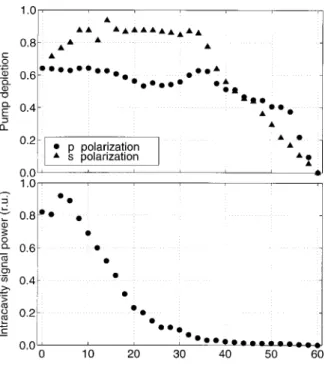
Figure 3 shows the intracavity signal power and the depletion of the p- and s-polarized components of the pump as functions of the polarization angle. At 36°, where the conversion is highest, the intracavity signal power is only 3.7% of its value at 0°. Note that the deple-tion of the s-polarized component is very high and is al-most constant for a wide range of polarization angle val-ues starting from a few degrees all the way to 36°. Increasing the polarization angle above its optimum value results in a rapid decline, because then the intrac-avity signal power is no longer high enough to deplete the s-polarized pump component.
Figure 4 shows power-conversion efficiency as a func-tion of pump power, where at each power level the polar-ization angle is optimized to yield maximum output power. The polarization rotation angle that maximizes
the output power at each pump power level is also shown in the figure. Note that neither the conversion efficiency nor the optimum angle changes significantly for a wide range of the pump power.
B. Group Delay
The p- and s-polarized components of the pump pulse have different group velocities in the KTP crystal and get separated from each other as they propagate inside the
Fig. 2. Power-conversion efficiency as a function of polarization rotation angle. The pump power is 515 mW, and the group de-lay is 2 ps.
Fig. 3. Pump depletion for the p-polarized and the s-polarized components and the intracavity signal power (in relative units) as functions of polarization rotation angle. The pump power is 515 mW, and the group delay is 2 ps. r.u., Relative units.
Fig. 4. Optimum polarization rotation angle and maximum power-conversion efficiency as functions of pump power.
crystal. (The calculated13group velocities of the interact-ing beams are 1.6631⫻ 108m/s for the p-polarized pump, 1.5763⫻ 108m/s for the s-polarized pump, 1.6896
⫻ 108m/s for the signal, 1.6094⫻ 108m/s for the idler,
and 1.5352⫻ 108m/s for the sum frequency.) Inasmuch
as the intracavity signal pulse is approximately synchro-nized with the p-polarized component (OPO pump), it falls out of synchronization with the s-polarized compo-nent (higher-frequency SFG input), thus reducing the ef-ficiency of the SFG process. To compensate partially for this mismatch we adjust the group delay between the p-and s-polarized components before the pump beam enters the cavity by translating M5 and M6.
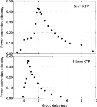
Figure 5 shows the power-conversion efficiency of the SF-OPO as a function of the group delay between the or-thogonally polarized pump components at the entrance of the crystal. At each value of the delay, the polarization angle is adjusted to maximize the output power, while the input pump power is kept constant at 515 mW. With no group-delay adjustment setup, or with the delay adjusted to zero, we measure a maximum of 13% power-conversion efficiency at a polarization angle of 33°. Introducing a group delay of 2 ps increases the conversion efficiency by more than threefold. This delay is approximately equal to the group-velocity delay between the signal and the
s-polarized pump component over 5 mm of KTP. For
comparison, Fig. 5 shows a set of similar data, for a 1.5-mm-long KTP crystal instead. The power-conversion ef-ficiency is 10.5%, when there is no delay. A 530-fs delay maximizes the power conversion-efficiency to 35%. Be-cause this crystal is shorter than the 5-mm-long crystal, it requires a shorter group delay at the input for maximum conversion.
C. Tuning
It is possible to tune the SF-OPO by changing the phase-matching angle and the pump wavelength at the same time. Calculated tuning curves for the SF-OPO are shown in Fig. 6 together with experimental data points. By varying in the 90°–60° range ( ⫽ 0°) and the pump wavelength in the 827–887 nm range, one can gen-erate an output wavelength of 487 to 554 nm. Tuning in the direction results in a narrower band compared with tuning in the direction; with varying from 0° to 30° ( ⫽ 90°) and the pump wavelength varying from 827 to 817 nm, the output wavelength is tuned from 487 to 478 nm. Experimentally, we have demonstrated tunability in the 484–512 nm range, being limited by the bandwidth of the cavity mirrors and by reflection losses from the crystal surfaces.
We obtained the experimental data shown in Fig. 6 by maximizing the output power by adjusting the pump wavelength at each phase-matching angle. At a given phase-matching angle there is only one pair of signal and pump wavelengths that results in the simultaneous phase matching of the parametric generation and SFG pro-cesses. If the pump wavelength deviates from this value, the signal wavelength gets shifted, while the OPO stays phase matched; however, the SFG process is no longer phase matched. Therefore the output power of the SF-OPO is sensitive to the pump wavelength.
The relatively long crystal poses a number of minor in-conveniences in tuning. Rotating the crystal not only changes the optical cavity length but also shifts the beams laterally. We can easily compensate for these ef-fects by translating M3 and slightly realigning M2. The size of the transverse cavity mode and hence its overlap
Fig. 5. Power-conversion efficiencies as functions of the group delay between the p- and the s-polarized pump components for 5-and 1.5-mm-long KTP crystals. The p-polarized component lags behind the s-polarized component for positive group-delay val-ues.
Fig. 6. Calculated tuning curves and measured values of output wavelength, pump wavelength, and output power across the tun-ing range for the SF-OPO. Angles are internal to the crystal. The filled circles represent experimental data points.
with the pump are influenced by the distance between M1 and M2, which also has to be readjusted after a rotation of the crystal.
D. Spectral and Temporal Characteristics
The spectrum and the autocorrelation of the sum-frequency output are shown in Fig. 7. The bandwidth of the spectrum is approximately 3.5 nm. The autocorrela-tion width of the sum-frequency pulses is measured to be 345 fs. When the output is deconvolved, assuming a se-cant hyperbolic (sech) shape, this corresponds to a pulse width of 225 fs, leading to a time–bandwidth product of unity. (For a transform-limited sech pulse the time– bandwidth product is 0.315.) The time–bandwidth prod-uct for the laser output is 0.45. This pulse broadening is due to group-velocity dispersion and the group-velocity mismatch between the p-polarized pump and the signal pulses in the KTP crystal. When we use a 1.5 mm-long KTP crystal, the pulse width of the sum-frequency beam reduces to 195 fs. This effect is due to reduced temporal overlap between the s-polarized pump and the signal.
To investigate the effects of group-velocity dispersion we constructed a linear (Fabry–Perot) cavity with intrac-avity dispersion-compensating prisms. Even though the presence of intracavity dispersion compensation reduced the bandwidth of the signal, it had little effect on the bandwidth or the pulse duration of the blue output beam.
4. PLANE-WAVE MODELING
Accurate modeling of the experiments reported in this pa-per requires one to include the effects of many expa-perimen- experimen-tal realities such as the temporal and transverse profiles of the pulses, group-velocity mismatch and dispersion, and self-phase modulation. We found that developing a plane-wave model that takes into account the temporal profile of the pulses and the group-velocity mismatch be-tween these pulses gives us the most insight into the com-putation time. Our model does not take into account the Gaussian beam nature of the fields, chirped pulses, or group-velocity dispersion.
We begin with a set of plane-wave coupled-mode equa-tions that govern the interaction of the pulses through the
nonlinear crystal that can be written as12 ai z ⫹ 1 vi ai t ⫽ ⫺jaapas*, (1) as z ⫹ 1 vs as t ⫽ ⫺j共aapai*⫹bafar*兲, (2) ap z ⫹ 1 vp ap t ⫽ ⫺jaaias, (3) ar z ⫹ 1 vr ar t ⫽ ⫺jbafas*, (4) af z ⫹ 1 vf af t ⫽ ⫺jbasar, (5)
where am and vm are normalized field amplitudes and group velocities for the idler (i), the signal (s), the pump ( p), the rotated pump (r), and the sum-frequency ( f ) pulses, respectively. These normalized field amplitudes are related to the electric fields Em through
am⫽ 共nmc⑀0/2បm兲1/2Em, m⫽ i, s, p, r, f, (6) such that 兩am兩2 represents the photon flux density for each field at frequencym. The nonlinear coupling coef-ficients are a⫽ da
冉
2ប c3⑀ 0冊
1/2冉
isp ninsnp冊
1/2 , (7) b⫽ db冉
2ប c3⑀ 0冊
1/2冉
srf nsnrnf冊
1/2 , (8)where da and db are the effective nonlinear coefficients for the OPO and the SFG processes, respectively, and nm are the refractive indices.
We used finite-differencing techniques to compute nu-merical solutions of Eqs. (1)–(5). In our calculations the pump field was modeled with a sech pulse shape. We started with a small-signal pulse that had the same sech shape as the pump to represent the parametric fluores-cence from which the cavity oscillations build up. This signal pulse was iterated through the cavity several times, until a steady state was reached. At each round trip a fixed delay was introduced to the signal pulse to model the adjustment of the cavity length with M3. The group delay between the p- and the s-polarized compo-nents of the pump at the input was also adjustable.
We computed the photon-conversion efficiency for a se-ries of cavity length (signal delay) values while keeping the polarization angle and the group delay constant. We found that, for a relevant range of polarization angle and group-delay values, the signal delay required for maxi-mizing the conversion efficiency is in the 380–480-fs range. This conclusion is in agreement with the 472-fs group delay between the p-polarized pump and the signal in 5 mm of KTP. The maximum conversion efficiency that we obtained by varying the cavity length was taken to be the conversion efficiency at this polarization angle and group delay.
Next we set the group delay between the pump compo-nents to 2 ps and calculated the conversion efficiency for different values of the polarization angle. Figure 8
Fig. 7. Autocorrelation trace (left) and spectrum (right) of the sum-frequency output beam.
shows the results of this calculation together with experi-mental data points. We made no attempt to fit the pre-dictions of the model to the data by adjusting any one of the physical parameters. The qualitative agreement of our model with the experimental results is highly satis-factory. The quantitative agreement for the peak photon conversion efficiency, the optimum polarization angle, and the threshold polarization angle is reasonably good.
At zero group delay we calculated the maximum photon conversion efficiency to be 22% at a polarization rotation angle of 30°. These results are also in reasonable agree-ment with those measured in our experiagree-ment.
Our model predicted a pulse width of 210 fs for the sum-frequency output, which is also in good agreement with the 225-fs value measured in the experiment. Be-cause our model does not take group-velocity dispersion into account, this agreement suggests that group-velocity mismatch is the dominating factor in determining the pulse width.
5. CONCLUSIONS
In conclusion, we have demonstrated a sum-frequency-generating optical parametric oscillator for which both parametric generation and sum-frequency generation are phase matched simultaneously in a single nonlinear crys-tal. This SF-OPO provides upconversion of an ultrafast Ti:sapphire laser with 43% power-conversion efficiency (50% photon-conversion efficiency) in the two-step process from the pump to the signal and then to the sum fre-quency. To our knowledge, the value of this conversion efficiency is the highest ever reported for an upconversion OPO. In addition, we have developed a plane-wave model that is in very good agreement with our experi-ments.
The simultaneous phase matching of two different second-order nonlinear processes within the same crystal opens many frequency-conversion possibilities.14 Recent reports of second-harmonic generation15–18 and SFG11,16,19within an OPO and within a cascaded OPO,20 parametric amplification with SFG,21and third-harmonic
generation22are some examples. Quasi-phase-matching
techniques will no doubt play a central role in realizing simultaneous phase matching.
ACKNOWLEDGMENT
This research was supported in part by the Turkish Sci-entific and Technical Research Council (Tubitak) under grants EEEAG-118 and 197E050.
O. Aytu¨ r can be reached at the address on the title page, by telephone at 90-312-290-2095, or by e-mail at [email protected].
REFERENCES
1. R. L. Byer and A. Piskarskas, eds., feature on optical para-metric oscillation and amplification, J. Opt. Soc. Am. B 10, 1655–2243 (1993); W. R. Bosenberg and R. C. Eckardt, eds., feature on optical parametric devices, J. Opt. Soc. Am. B 12, 2083–2320 (1995); C. L. Tang, W. R. Bosenberg, T. Ukachi, R. J. Lane, and L. K. Cheng, ‘‘Optical parametric oscilla-tors,’’ Proc. IEEE 80, 365–374 (1992).
2. D. A. Roberts, ‘‘Simplified characterization of uniaxial and biaxial nonlinear optical crystals,’’ IEEE J. Quantum Elec-tron. 28, 2057–2074 (1992).
3. L. E. Myers, R. C. Eckardt, M. M. Fejer, R. L. Byer, W. R. Bosenberg, and J. W. Pierce, ‘‘Quasi-phase-matched optical parametric oscillators in bulk periodically poled LiNbO3,’’ J. Opt. Soc. Am. B 12, 2102–2116 (1995).
4. H. M. van Driel, ‘‘Synchronously pumped optical paramet-ric oscillators,’’ Appl. Phys. B 60, 411–420 (1995).
5. D. C. Edelstein, E. S. Wachman, and C. L. Tang, ‘‘Broadly tunable high repetition rate femtosecond optical parametric oscillator,’’ Appl. Phys. Lett. 54, 1728–1730 (1989); W. S. Pelouch, P. E. Powers, and C. L. Tang, ‘‘Ti:sapphire pumped, high-repetition-rate femtosecond optical paramet-ric oscillator,’’ Opt. Lett. 17, 1070–1072 (1992); Q. Fu, G. Mak, and H. M. van Driel, ‘‘High-power, 62-fs infrared op-tical parametric oscillator synchronously pumped by a 76-MHz Ti:sapphire laser,’’ Opt. Lett. 17, 1006–1008 (1992); G. Mak, Q. Fu, and H. M. van Driel, ‘‘Externally pumped high repetition rate femtosecond infrared optical parametric os-cillator,’’ Appl. Phys. Lett. 60, 542–544 (1992); P. E. Pow-ers, C. L. Tang, and L. K. Cheng, ‘‘High-repetition-rate fem-tosecond optical parametric oscillator based on CsTiOAsO4,’’ Opt. Lett. 19, 37–39 (1994).
6. T. J. Driscoll, G. M. Gale, and F. Hache, ‘‘Ti:sapphire 2nd-harmonic-pumped visible range femtosecond optical para-metric oscillator,’’ Opt. Commun. 110, 638–644 (1994). 7. A. Nebel, H. Frost, R. Beigang, and R. Wallenstein, ‘‘Visible
femtosecond pulses by second harmonic generation of a cw mode-locked KTP optical parametric oscillator,’’ Appl. Phys. B 60, 453–458 (1995).
8. R. J. Ellingson and C. L. Tang, ‘‘High-power high-repetition-rate femtosecond pulses tunable in the visible,’’ Opt. Lett. 18, 438–440 (1993); D. T. Reid, M. Ebrahimza-deh, and W. Sibbett, ‘‘Efficient femtosecond pulse genera-tion in the visible in a frequency-doubled optical parametric oscillator based on RbTiOAsO4,’’ J. Opt. Soc. Am. B 12, 1157–1163 (1995).
9. E. C. Cheung, K. Koch, and G. T. Moore, ‘‘Frequency upcon-version by phase-matched sum-frequency generation in an optical parametric oscillator,’’ Opt. Lett. 19, 1967–1969 (1994).
10. A. Shirakawa, H. W. Mao, and T. Kobayashi, ‘‘Highly effi-cient generation of blue–orange femtosecond pulses from intracavity-frequency-mixed optical parametric oscillator,’’ Opt. Commun. 123, 121–128 (1996).
11. K. G. Ko¨pru¨ lu¨, T. Kartalog˘lu, and O. Aytu¨r, ‘‘Single-crystal sum-frequency generating optical parametric oscillator,’’ in Conference on Lasers and Electro-Optics, Vol. 11 of 1997
Fig. 8. Photon-conversion efficiency as a function of the polar-ization angle. Solid curve, theoretical plane-wave model; filled circles, experimental data points.
OSA Technical Digest Series (Optical Society of America, Washington, D.C., 1997), pp. 457–458.
12. O. Aytu¨ r and Y. Dikmelik, ‘‘Plane wave theory of self-doubling optical parametric oscillators,’’ IEEE J. Quantum Electron. 34, 447–458 (1998); Y. Dikmelik, G. Akgu¨n, and O. Aytu¨ r, ‘‘Plane-wave dynamics of optical parametric oscil-lation with simultaneous sum-frequency generation,’’ IEEE J. Quantum Electron. 35, 897–912 (1999).
13. K. Kato, ‘‘Parametric oscillation at 3.2m in KTP pumped at 1.064m,’’ IEEE J. Quantum Electron. 27, 1137–1140 (1991).
14. R. A. Andrews, H. Rabin, and C. L. Tang, ‘‘Coupled para-metric downconversion and upconversion with simulta-neous phase matching,’’ Phys. Rev. Lett. 25, 605–608 (1970).
15. T. Kartalog˘lu, K. G. Ko¨pru¨ lu¨, and O. Aytu¨r, ‘‘Phase-matched self-doubling optical parametric oscillator,’’ Opt. Lett. 22, 280–282 (1997).
16. K. C. Burr, C. L. Tang, M. A. Arbore, and M. M. Fejer, ‘‘Broadly tunable mid-infrared femtosecond optical para-metric oscillator using all-solid-state-pumped periodically poled lithium niobate,’’ Opt. Lett. 22, 1458–1460 (1997).
17. C. McGowan, D. T. Reid, Z. E. Penman, M. Ebrahimzadeh, W. Sibbett, and D. H. Jundt, ‘‘Femtosecond optical
para-metric oscillator based on periodically poled lithium nio-bate,’’ J. Opt. Soc. Am. B 15, 694–701 (1998).
18. D. T. Reid, G. T. Kennedy, A. Miller, W. Sibbett, and M. Ebrahimzadeh, ‘‘Widely tunable, near- to mid-infrared fem-tosecond and picosecond optical parametric oscillators using periodically poled LiNbO3and RbTiOAsO4,’’ IEEE J. Sel. Top. Quantum Electron. 4, 238–248 (1998).
19. S. D. Butterworth, P. G. R. Smith, and D. C. Hanna, ‘‘Pico-second Ti:sapphire-pumped optical parametric oscillator based on periodically poled LiNbO3,’’ Opt. Lett. 22, 618– 620 (1997).
20. M. Vaidyanathan, R. C. Eckardt, V. Dominic, L. E. Myers, and T. P. Grayson, ‘‘Cascaded optical parametric oscilla-tions,’’ Opt. Express 1, 49–53 (1997), http://epubs.osa.org/ opticsexpress.
21. V. Petrov and F. Noack, ‘‘Frequency upconversion of tun-able femtosecond pulses by parametric amplification and sum-frequency generation in a single nonlinear crystal,’’ Opt. Lett. 20, 2171–2173 (1995).
22. O. Pfister, J. S. Wells, L. Hollberg, L. Zink, D. A. van Baak, M. D. Levenson, and W. R. Bosenberg, ‘‘Continuous-wave frequency tripling and quadrupling by simultaneous three-wave mixings in periodically poled crystals: application to a two-step 1.19–10.71-m frequency bridge,’’ Opt. Lett. 22, 1211–1213 (1997).