Improved Efficiency of Thin Film a-Si:H Solar Cells with
Au Nanoparticles
Kazi Islam
1, Aaesha Alnuaimi
1, Ali Kemal Okyay
2and Ammar Nayfeh
11
Institute Center for Future Energy Systems (iFES), Masdar Institute of Science and Technology,
PO BOX 54224, Abu Dhabi, UAE
2
UNAM, Bilkent University, Ankara, Turkey
Abstract — In this work, the effect of Au nanoparticles on theperformance of a-Si:H solar cells is investigated experimentally. Au nanoparticles of 10, 20, 50, 80, 100, 200 and 400 nm are spin coated on ITO before metallization. The results show an increase in the Jsc and efficiency with increasing nanoparticle size. The Jsc
increases from 9.34 mA/cm2 to 10.1 mA/cm2. In addition, the
efficiency increases from 4.28% to 5.01%.
Index Terms —nanoparticles, photovoltaics, plasmonics, thin
film, solar cells, amorphous Si
I. INTRODUCTION ANDMOTIVATION
Effective light trapping mechanisms are important for the improved performance of thin film solar cells. For enhanced absorption in thin film solar cells, different approaches such as surface texturing and back reflectors have been described in [1-2]. More recently, nanotechnology has been used with plasmonic light trapping of metal nanoparticles (NP) like gold (Au) or silver (Ag) [3-5]. For incorporating metal NPs into solar cells, different methods have been established that includes island annealing and colloidal metal particles [6-7]. Also, some numerical models have been developed to understand the plasmonic effect [8]. In this work, the effect of Au nanoparticles on the performance of thin film a-Si:H n-i-p solar cells is studied.
II. PLASMONIC ENHANCEMENT
Surface plasmons are collective oscillations of the free charges at a metal boundary. Metals support surface plasmons, either localized as for metal nanoparticles or propagating in case of planar metal surfaces. By controlling the size and shape of the metallic nanostructures, the surface plasmon resonance or plasmon propagating properties can be varied. Since the surface resonances of metals are mostly in the visible or in the infrared region of the electromagnetic spectrum, they are of particular interest for photovoltaic application. Two prominent mechanisms can explain the contribution of metallic nanoparticles based on application: scattering mechanism and the near-field localization effect [9]. Photocurrent enhancement by metal nanoparticles on the top surface of solar cells can be explained by the light scattering mechanism. Metal nanoparticles are strong
scatterers of light at wavelengths near their resonant frequency [10].
A point dipole model can describe the absorption and scattering of the incoming light by the nanoparticls for particles with diameters well below the wavelength the incoing light. The scattering and absorption cross-sections are given by the following equations [10]:
( ) | | (1) [ ] (2)
where
[ ⁄
⁄ ] (3)
is the polarizability of the particle. Here V is the particle volume, εp is the dielectric function of the particle and εm is the
dielectric function of the embedding medium. From (3), its quite obvious that at εp = −2εm the particle polarizability will
become very large. This very concept is termed as the surface plasmon resonance.
At the surface plasmon resonance, the scattering cross-section exceeds the geometrical cross cross-section of the nanoparticles e.g. silver nanoparticles in air has a scattering cross-section that is approximately ten times the crosssectional area of the particle at the resonant frequency[11]. In such a case, a substrate covered with a 10 % areal density of Fig. 1. Scattering of incoming light due to nanoparticles on top of ITO. (Figure not to scale)
nanoparticles can fully absorb and scatter the incoming light, to first-order [11][12]. For light trapping it is important that scattering is more efficient than absorption, a condition that is met for comparatively larger nanoparticles as can be seen from (1) and (2) [4].
Nanoparticle size, shape and distribution over the surface will determine the effect of the nanoparticles on the performance of the photovoltaic device [13].
III. STRUCTURE AND FABRICATION PROCESS
Fig. 2 shows the structure of the fabricated a-Si:H n-i-p solar cell. The structure is a stack of 80 nm ITO, 20 nm heavily doped n-type a-Si, 500 nm undoped a-Si and finally 20 nm heavily doped p-type a-Si on a p+-type Si wafer. The p+ Si substrate serves as the back contact, and does not contribute significantly to the carrier generation. After the ITO etch, Au NP of various sizes in solution were spin-coated.
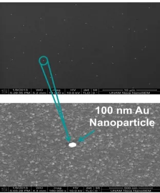
Seven different diameter-size, 10 nm, 20 nm, 50 nm, 80 nm, 100 nm, 200 nm and 400 nm particle sizes were investigated. The spin coating recipe was optimized to obtain uniform distribution and high concentration of particles on the surface, simultaneously and was set to 2000 rpm, 1000 acceleration and spinning for 60 seconds. Fig. 4 is an SEM image of the top surface showing the Au NP on the ITO.
After the NP coating, 100 nm of silver was deposited using Thermal Physical Vapor Deposition (PVD) tools. Three different cell area-sizes were fabricated i.e. 1 cm x 1cm, 0.5 cm x 0.5 cm and 0.25 cm x 0.25 cm. Fig. 3 shows the top view of final solar cell structure fabricated. Unless otherwise stated, solar cells of size 0.25 cm × 0.25 cm are presented in this work.
IV. EXPERIMENTAL RESULTS AND ANALYSIS Fig. 2. Cross-section of the fabricated ITO/a-Si:H solar cell
with Au nanoparticles deposited on the top surface. (Figure not to scale)
Fig. 4. SEM image of the top surface of the fabricated n-i-p a-Si:H solar cell with 100 nm Au nanoparticles on the ITO surface.
Fig. 5. Measured J-V characteristics of n-i-p a-Si:H reference cell without nanoparticles and cells with 10 nm and 400 nm Au nanoparticles.
Fig. 3. Top view photograph of the fabricated solar cell.
Fig. 5 shows the J-V curve for the reference cell without NP and cells with 10 nm and 400 nm NP. The Voc is constant at
0.89 V while the Jsc improves with larger NP size. Fig. 6 plots
Jsc vs. NP size. The Jsc increases from 9.34 mA/cm2 to 10.1
mA/cm2. Fig. 7 plots the median reflectance across all
wavelengths vs. NP size. The reflectance drops from 23.19% with no Au NP to less than 20% for all NP sizes. The drop shows the improved surface scattering due to the Au nanoparticles.
Fig. 8 plots the efficiency vs. NP size. The efficiency increases with increasing NP size due the increase in the Jsc.
The efficiency increases from 4.28% to 5.1%. The Voc does
not change with NP size. The fill factor (FF) increases from 51% for the reference cell up to 56% for the Au NP based cell. For the most part the FF does not change with NP size.
Fig. 9 plots the External Quantum Efficiency (EQE) of the reference cell, 10nm and 400nm Au NPs. The results show an improved spectral response with increasing NP size. The peak EQE is 59% for the cell with 400 nm NP while the reference cell has 43% peak EQE. The EQE predicts that there should be a 41.6% increase in the Jsc for the 400 nm NP cell with
respect to the no NP cell. From the actual measurement, the Jsc
increases from 9.34 mA/cm2 for the no NP cell to 10.13
mA/cm2 for the 400 nm NP cell, which is 8.46% increment.
More investigations are required to further explain this mismatch.
Table I summarizes the main findings of this work, listing the Jsc and efficiency of the solar cells with respect to the Au
NP size. The Jsc increases by 8.46% with the introduction of
NP for the best case and the efficiency improves by 17.06% with NP for the best case as well. Both the Jsc and efficiency
tend to improve with larger NP sizes. Fig. 6. Jsc vs. Au nanoparticle size (plotted in log scale) for Au
nanoparticle enhanced plasmonic n-i-p a-Si:H solar cells.
Fig. 7. Median reflectance vs. Au nanoparticle size (plotted in log scale) for Au nanoparticle enhanced plasmonic n-i-p a-Si:H solar cells.
Fig. 8. Efficiency vs. Au nanoparticle size (plotted in log scale) for Au nanoparticle enhanced plasmonic n-i-p a-Si:H solar cells.
Fig. 9. Measured external quantum efficiency of n-i-p a-Si:H reference cell without nanoparticles and cells with 10 nm and 400 nm Au nanoparticles.
V. CONCLUSIONS
In summary, the effect of Au nanoparticles on the performance of a-Si:H thin film solar cells was studied. The results show an increase in Jsc, efficiency and spectral
response with the Au nanoparticles. The results highlight a promising and simple enhancement for future thin film solar cells using nanoparticles.
ACKNOWLEDGEMENT
We would like to thank the students and the technical staff of UNAM at Bilkent University, Turkey for their help with the fabrication. We gratefully acknowledge financial support for this work provided by the Masdar Institute of Science and Technology.
REFERENCES
[1] M. Berginski et al. "Recent development on surface-textured ZnO: Al films prepared by sputtering for thin-film
solar cell application." Thin Solid Films 516.17 (2008): 5836-5841.
[2] V. E. Ferry et al. "Improved red-response in thin film a-Si: H solar cells with soft-imprinted plasmonic back reflectors." Applied physics letters 95.18 (2009): 183503-183503.
[3] H. A Atwater and Albert Polman. "Plasmonics for improved photovoltaic devices." Nature materials 9.3 (2010): 205-213.
[4] K. R. Catchpole, and Albert Polman. "Plasmonic solar cells." Optics express 16.26 (2008): 21793-21800.
[5] Y. A Akimov, K. Ostrikov, and E. P. Li. "Surface plasmon enhancement of optical absorption in thin-film silicon solar cells." Plasmonics 4.2 (2009): 107-113.
[6] F.J. Beck, A. Polman, and K. R. Catchpole. "Tunable light trapping for solar cells using localized surface plasmons." Journal of Applied Physics 105.11 (2009): 114310-114310. [7] D. Derkacs, S. H. Lim, P. Matheu, W. Ma, E.T. Yu, “Improved performance of amorphous silicon solar cells via scattering from surface plasmon polaritons in nearby metallic nanoparticles,” Applied Physics Letters, 89(9), 093103-093103 (2006)
[8] Yu. A Akimov, W. S. Koh, and K. Ostrikov. "Enhancement of optical absorption in thin-film solar cells through the excitation of higher-order nanoparticle plasmon modes." Optics express 17.12 (2009): 10195-10205.
[9] Temple, T. L., G. D. K. Mahanama, H. S. Reehal, and D. M. Bagnall. "Influence of localized surface plasmon excitation in silver nanoparticles on the performance of silicon solar cells." Solar Energy Materials and Solar Cells 93, no. 11 (2009): 1978-1985.
[10] Bohren, Craig F., and Donald R. Huffman. Absorption and scattering of light by small particles. Wiley-Vch, 2008. [11] B.J.Soller and D.G Hall, “Scattering enhancement from an
array of interacting dipoles near a planar waveguide,” JOSA B, 19(10), 2437-2448 (2002)
[12] K.R Catchpole and S. Pillai. "Absorption enhancement due to scattering by dipoles into silicon waveguides." Journal of applied physics 100.4 (2006): 044504-044504.
[13] Kelly, K. Lance, et al. "The optical properties of metal nanoparticles: the influence of size, shape, and dielectric environment." The Journal of Physical Chemistry B 107.3 (2003): 668-677. TABLE I SUMMARY OF RESULTS Au NP Size (nm) Jsc (mA/cm2) η (%) 0 9.34 4.28 10 9.76 4.84 20 9.89 4.89 50 9.9 4.9 80 9.96 4.93 100 10.1 4.97 200 10.11 5.01 400 10.13 5.01 978-1-4799-3299-3/13/$31.00 ©2013 IEEE 1876