Optical antenna of comb-shaped split ring
architecture for increased field localization in
NIR and MIR
Veli Tayfun Kilic,1,* Vakur B. Erturk,1 and Hilmi Volkan Demir1,2,3
1Department of Electrical and Electronics Engineering, Department of Physics, and UNAM- Institute of Materials Science and Nanotechnology, Bilkent University, Ankara 06800, Turkey
2School of Electrical and Electronic Engineering, School of Physical and Mathematical Sciences, Nanyang Technological University, Nanyang Avenue, Singapore, 639798, Singapore
3[email protected] *[email protected]
Abstract: We propose and demonstrate novel designs of optical antennas based on comb-shaped split ring architecture that display multi resonance field intensity enhancement spectrum. These nanoantennas achieve substantially increased field localization at longer wavelengths than that of a single or an array of dipoles with the same side length. With these optical antennas, localizing near infrared (NIR) and mid infrared (MIR) lights within a region of tens of nanometers at an intensity enhancement level of the order of thousands of magnitude can be accomplished.
©2013 Optical Society of America
OCIS codes: (240.6680) Surface plasmons; (260.5740) Resonance; (310.6628) Subwavelength structures, nanostructures; (260.3910) Metal optics.
References and links
1. D. K. Gramotnev and S. I. Bozhevolnyi, “Plasmonics beyond the diffraction limit,” Nat. Photonics 4(2), 83–91 (2010).
2. H. Raether, Surface Plasmons on Smooth and Rough Surfaces and on Gratings (Springer, 1988). 3. M. Born and E. Wolf, Principles of Optics (Cambridge University, 1999).
4. G. Campardo, F. Tiziani, and M. Iaculo, Memory Mass Storage (Springer, 2011), Chap. 8. 5. L. Novotny and N. van Hulst, “Antennas for light,” Nat. Photonics 5(2), 83–90 (2011).
6. K.-S. Lee and M. A. El-Sayed, “Gold and silver nanoparticles in sensing and imaging: Sensitivity of plasmon response to size, shape, and metal composition,” J. Phys. Chem. B 110(39), 19220–19225 (2006).
7. V. T. Kilic, V. B. Erturk, and H. V. Demir, “Three-dimensional study of planar optical antennas made of split-ring architecture outperforming dipole antennas for increased field localization,” Opt. Lett. 37(2), 139–141 (2012).
8. B. C. Stipe, T. C. Strand, C. C. Poon, H. Balamane, T. D. Boone, J. A. Katine, J.-L. Li, V. Rawat, H. Nemoto, A. Hirotsune, O. Hellwig, R. Ruiz, E. Dobisz, D. S. Kercher, N. Robertson, T. R. Albrecht, and B. D. Terris, “Magnetic recording at 1.5 Pb m-2 using an integrated plasmonic antenna,” Nat. Photonics 4(7), 484–488 (2010).
9. J. Zhang, J. Yang, X. Wu, and Q. Gong, “Electric field enhancing properties of the V-shaped optical resonant antennas,” Opt. Express 15(25), 16852–16859 (2007).
10. H. Tamaru, H. Kuwata, H. T. Miyazaki, and K. Miyano, “Resonant light scattering from individual Ag nanoparticles and particle pairs,” Appl. Phys. Lett. 80(10), 1826–1828 (2002).
11. R. M. Bakker, A. Boltasseva, Z. Liu, R. H. Pedersen, S. Gresillon, A. V. Kildishev, V. P. Drachev, and V. M. Shalaev, “Near-field excitation of nanoantenna resonance,” Opt. Express 15(21), 13682–13688 (2007). 12. H. Fischer and O. J. F. Martin, “Engineering the optical response of plasmonic nanoantennas,” Opt. Express
16(12), 9144–9154 (2008).
13. E. Cubukcu, E. A. Kort, K. B. Crozier, and F. Capasso, “Plasmonic laser antenna,” Appl. Phys. Lett. 89(9), 093120 (2006).
14. P. Mühlschlegel, H.-J. Eisler, O. J. F. Martin, B. Hecht, and D. W. Pohl, “Resonant optical antennas,” Science 308(5728), 1607–1609 (2005).
15. A. Sundaramurthy, K. B. Crozier, G. S. Kino, D. P. Fromm, P. J. Schuck, and W. E. Moerner, “Field
enhancement and gap-dependent resonance in a system of two opposing tip-to-tip Au nanotriangles,” Phys. Rev. B 72(16), 165409 (2005).
16. P. J. Schuck, D. P. Fromm, A. Sundaramurthy, G. S. Kino, and W. E. Moerner, “Improving the mismatch between light and nanoscale objects with gold bowtie nanoantennas,” Phys. Rev. Lett. 94(1), 017402 (2005). 17. R. Melik, E. Unal, N. K. Perkgoz, B. Santoni, D. Kamstock, C. Puttlitz, and H. V. Demir, “Nested metamaterials
for wireless strain sensing,” IEEE J. Sel. Top. Quantum Electron. 16(2), 450–458 (2010). 18. E. D. Palik, Handbook of Optical Constants of Solids (Academic, 1985).
1. Introduction
Collective electron oscillations in metals enable optical excitation based on the interaction of the conduction electrons in metals with the incident electromagnetic field. Such plasmonic interactions are of fundamental importance, as they allow for confining fields beyond the diffraction limit [1, 2]. As a result, today plasmonics is exploited in a wide range of applications spanning from waveguides to transmission apertures to imaging to spectroscopy and to biological sensors.
In some applications such as optical data storage, to increase the data capacity, shorter wavelengths are being used because in traditional optical systems the focused light is constrained with the diffraction limit [3, 4]. On the other hand, plasmonic applications such as waveguides and transmission apertures help us to confine light in a region smaller than the diffraction limit. However, resulting electromagnetic excitations die out very quickly as we move away from the plasmonic structure. Therefore, obtaining highly localized field is a requirement for plasmonic applications. Plasmonic structures such as optical antennas accomplish this requirement by obtaining field spots at very high intensities in a region beyond the diffraction limit [5]. Consequently, they offer a wide variety of important applications including scanning near field optical microscopy, ultra-high density data storage and very sensitive optical detectors.
Recently, optical antennas of various geometries such as rod [6], split ring resonator (SRR) [7], E-shape [8], V-shape [9], spherical [10], elliptical [11], etc. have been reported in literature. Among them dipole and bow-tie nanoantennas have been investigated mostly because of their easy geometries [12–16]. Single nanoantennas and/or array of such nanoantennas with these geometries have been studied both numerically and experimentally.
In this work, we propose comb-shaped split ring nanoantennas that resonate at much longer wavelengths than the single dipoles or the array of such dipoles with the same side lengths along the incident field polarization. In these comb-shaped designs, the field intensity enhancements inside the gap regions are significantly increased compared to the cases of a single or array of dipoles, despite the fact that their side lengths are considerably reduced with respect to their resonance wavelengths. Moreover, these nanoantennas can also resonate around the same frequency band as that of a single dipole or array of dipoles with comparable levels of field enhancement. Therefore, the proposed comb-shaped nanoantennas can be useful for multiband applications.
2. Simulation method and geometry
Previously, we examined optical antennas having split ring resonator architecture [7] and observed a large field enhancement with a simple connection that allows for continuous current flow. Inspired by this observation, we implement a comb-shaped architecture, which was previously studied as a nested split ring resonator for sensing in the RF range [17]. Here, different than the previous reports, we aim at increasing the field localization inside gap regions of the comb-shaped resonator at multiple frequency bands. Therefore, we numerically study these nanoantennas made of gold (Au) on silica (SiO2) with a varying number of comb
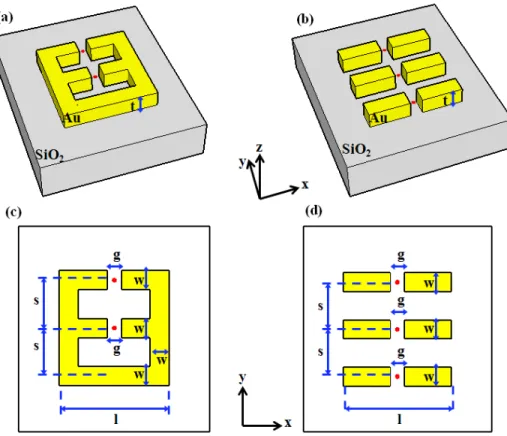
teeth and compare their performance with that of a single and array of dipoles. As an example, the structures of a comb-shaped nanoantenna with two teeth and a three-dipole nanoantenna array are depicted in Fig. 1.
Fig. 1. Three-dimensional (3D) structures of (a) a comb-shaped nanoantenna with two teeth and (b) a three-dipole nanoantenna array, and their perspective views in (c) and (d), respectively, seen from constant z plane passing through the gap center points. In the figure red dots represent the gap center points.
In our designs, we use SiO2 as our substrate because of its low cost and fabrication
compatibility. The real and imaginary parts of its refractive index are set to constant values 1.4 and 0, respectively. Hence, we model the substrate to be transparent over a wide wavelength regime including visible, NIR and MIR spectra and make the resonance dependency on the antenna structure more obvious. Also the metal is selected as Au [18] because of its high melting temperature and well known optical properties over the same wide wavelength region. In addition, each dipole and each comb tooth have 100 nm long, 40 nm thick (t) and 40 nm wide (w) arms, and each gap (g) is 30 nm long. Thus we have dipoles and comb teeth with a side length (l) of 230 nm. Also the separation of each dipole in array antennas and each tooth in comb antennas (center to center distance) in y-direction (s) are set to 100 nm. These geometrical parameters are kept constant in all our simulations to prevent unfair comparisons.
In our simulations, the antennas are illuminated from the substrate side with a plane wave polarized along the x-direction and we examine the field enhancement at the gap center points over a wide wavelength regime spanning from 400 to 7000 nm by using finite-difference time-domain (FDTD) tool (Lumerical Solutions Inc., Canada). The field intensity enhancement at the gap center point is calculated by
2 2
field enhancement= gap inc E
where Egap is the field at the gap center point and Einc is the incident field. In our 3D simulations, the gap regions and the remaining metal parts of antennas are meshed uniformly with 1 and 2.5 nm mesh sizes, respectively, and the computation domain is truncated using perfectly matched layers (PML).
3. Results and discussion
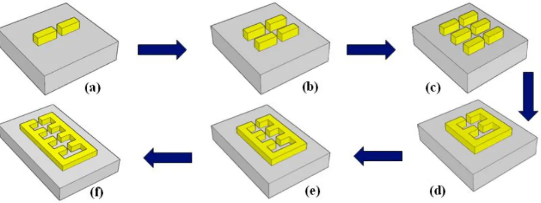
The evolution of our comb-shaped nanoantenna design is illustrated step by step in Fig. 2 starting from a single dipole to a comb-shaped nanoantenna with four teeth.
Fig. 2. Evolution steps of our comb-shaped nanoantenna with four teeth.
As can be seen from Fig. 2, the starting point of our simulations is a single dipole nanoantenna, whose resonance behavior calculated at its gap center point is shown in Fig. 3. Based on the simulations, the maximum field intensity enhancement of a single dipole nanoantenna is 294.1 at the resonance wavelength of 740 nm.
1 2 3 4 5 6 7 0 100 200 300 Wavelength(μm) In te ns it y E nh an cem en t
Fig. 3. Field intensity enhancement spectrum of a single dipole nanoantenna calculated at its gap center point.
Subsequently, the intensity enhancements at the gap center points of two- and three-dipole arrays are studied. Because of interactions between the antennas, the intensity enhancement spectrums of dipoles change. In the two-dipole array, a single peak is observed at the resonance wavelength of 760 nm with an intensity enhancement value of 130.4 at the gap center points of antennas. On the other hand, in the three-dipole array, two peaks arise at the gap center point of the inner antenna at resonance wavelengths of 700 and 760 nm. At these resonance wavelengths, the field intensity enhancements of 31.6 and 103.4 are recorded, respectively. However, at the gap center points of the outer dipoles only a single peak is observed at a resonance wavelength of 730 nm with a field intensity enhancement of 133.4.
As the next step, to increase the field localization inside the gap regions we connect one end of the three-dipole array and obtain the comb-shaped nanoantenna with two teeth as
illustrated in Fig. 2(d). Using the same illumination that is used for a single dipole and array of dipoles, the field intensity enhancements at the gap center points are examined.
1 2 3 4 5 6 7 0 500 1000 1500 2000 2500 Wavelength(μm) In ten si ty E nh an cem en t 1 2 3 4 5 6 7 0 500 1000 1500 Wavelength(μm) In ten si ty E nh an cem en t (a) (b)
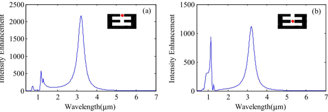
Fig. 4. Field intensity enhancement spectrum for two-teeth comb-shaped nanoantenna calculated at the center points of (a) the outer and (b) the inner gap. Here, the outer and inner gap centers are marked with red dots in the corresponding inner drawings.
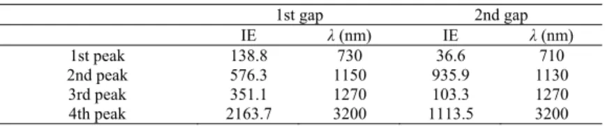
Figure 4 shows the calculated field intensity spectrum for the two-teeth comb-shaped nanoantenna at the outer gap center point [Fig. 4(a)] and at the inner gap center point [Fig. 4(b)], whereas Table 1 presents the intensity enhancements (IE) and the corresponding wavelengths of the same antenna. As can be seen both from the figures and Table 1, the most significant field IEs are found to be 2163.7 and 1113.5 inside the outer and inner gaps, respectively, at the resonance wavelength (λ) of 3200 nm. This means that we have the IE levels in the range of 103 inside the gaps of about λ/107 using teeth with an electrical length
of about λ/14. When compared to the maximum field IE of a single dipole nanoantenna, a field IE of 294.1 is observed in a gap of about λ/25 with an electrical length of about λ/3 at
λ = 740 nm resonance wavelength as illustrated in Fig. 3. Consequently, these results together
with the two- and three-dipole array results show that the resonance wavelength of an array of dipoles shifts towards longer wavelengths as we connect one end of the dipoles and obtain the comb-shaped architecture. Moreover, larger field enhancements are observed inside the gap regions of the comb-shaped nanoantenna than that of a single and array of dipoles with the same side length. On the other hand, it is worth noting that significant field IEs are obtained at multiple resonance wavelengths. Apart from the dominant field IE achieved at
λ = 3200 nm, the amount of field IEs achieved at smaller wavelengths are also higher or
comparable to that of two- and/or three-dipole arrays (for instance, the IE around 730 nm). Therefore, this nanoantenna can be used for multiband applications.
We further study the comb-shaped nanoantennas with three and four teeth for comparison purposes. The resulting peak field intensity enhancements and the corresponding resonance wavelengths inside each gap of the comb-shaped nanoantennas with three and four teeth are tabulated in Tables 2 and 3, respectively. In all tables (including Table 1), the smallest gap number (i.e., the 1st gap) indicates the gap located at the furthest point from the connected end and the gap number increases as the gap is closer to the connecting end. This gap numbering together with the field localizations inside the gap regions of a comb-shaped nanoantenna with four teeth at the resonance wavelength of 5080 nm are illustrated in Fig. 5 (here with the color bar being limited to 300 to guide the eye for the localization of the bright spots). On this plane, we observe that the optical antenna localizes the energy incident over the metallic part into its gaps.
Table 1. Peak Field Enhancements and Resonance Wavelengths of Comb-Shaped Nanoantenna with two teeth
1st gap 2nd gap IE λ (nm) IE λ (nm) 1st peak 138.8 730 36.6 710 2nd peak 576.3 1150 935.9 1130 3rd peak 351.1 1270 103.3 1270 4th peak 2163.7 3200 1113.5 3200
Table 2. Peak Field Enhancements and Resonance Wavelengths of Comb-Shaped Nanoantenna with three teeth
1st gap 2nd gap 3rd gap
IE λ (nm) IE λ (nm) IE λ (nm)
1st peak 145.1 750 73.8 750 403.4 1020
2nd peak 129.3 1030 550.2 1050 181.2 1240
3rd peak 478.6 1520 151.3 1450 702.5 1490
4th peak 1723.9 4150 1222.2 4150 540.9 4150
Table 3. Peak Field Enhancements and Resonance Wavelengths of Comb-Shaped Nanoantenna with four teeth
1st gap 2nd gap 3rd gap 4th gap
IE λ (nm) IE λ (nm) IE λ (nm) IE λ (nm) 1st peak 148.0 750 90.8 750 44.1 700 302.2 990 2nd peak 263.5 1140 115.9 1010 159.8 1020 515.3 1140 3rd peak 47.9 1270 381.5 1160 314.9 1180 82.1 1270 4th peak 451.6 1820 235.1 1270 263.8 1270 547.8 1790 5th peak 1360.2 5080 61.7 1870 386.5 1770 286.2 5080 6th peak x x 1096.8 5080 692.8 5080 x x
Here, x indicates that there are no more peaks in wavelength regime that we consider. Also, IE and λ represent intensity enhancement and resonance wavelength, respectively.
Fig. 5. Field intensity enhancement distribution of four-teeth comb-shaped nanoantenna on constant z plane passing through the gap centers at the resonance wavelength of 5080 nm. Here, the gap numbers are denoted with white numerals and the color bar is limited to 300 for clarity.
The results tabulated in all tables indicate that the main resonance (i.e., the strongest field intensity enhancement) shifts towards longer wavelengths as the number of teeth increases in all comb-shaped nanoantennas. Besides, similar to the two-teeth case, additional resonances at shorter wavelengths are obtained. Some of them are around the same wavelength as that of the single and array of dipoles, and the field IE at these wavelengths are comparable with that of the single and/or array of dipoles.
Finally, studies for comb-shaped nanoantennas have been repeated for different sizes, and similar improved field intensity enhancements as well as multiband properties have been observed.
4. Conclusion
In this work we numerically study and demonstrate the resonance behavior of comb-shaped optical antennas. It has been observed that the comb-shaped nanoantennas resonate at longer wavelengths, and the total field intensity enhancements at these resonance wavelengths are significantly stronger than those in the dipole cases (single or array of dipoles) when the side lengths are kept the same. Localizing NIR and MIR lights within a region of tens of nanometers can be achieved at an intensity enhancement level of the order of thousands of magnitude by these comb-shaped structures. In addition, in the comb-shaped nanoantennas, as a result of adding comb teeth the main resonance shifts towards longer wavelengths and additional resonances emerge at shorter wavelengths, where these new resonance values are comparable to the dipole antenna resonances. We believe that such comb-shaped optical antennas are promising for applications that require intense optical spots beyond the diffraction limit in NIR and MIR and/or in applications that require multiband strong field localizations.
Acknowledgments
We gratefully acknowledge financial support from European Science Foundation (ESF) EURYI, EC-FP7 N4E NoE, TUBA, and TUBITAK 112E183, and 110E217 as well as Singapore National Research Foundation under the program numbers NRF-CRP-6-2010-02 and NRF-RF-2009-09. VTK also thanks the TUBITAK-BIDEB for the financial support.