A NEW LYOTROPIC LIQUID CRYSTALLINE SYSTEM:
OLIGO(ETHYLENE OXIDE) SURFACTANTS WITH TRANSITION METAL COMPLEXES (M(H2O)nXm) AND THE SYNTHESIS OF
MESOPOROUS METAL SULFIDES
A THESIS
SUBMITTED TO THE DEPARTMENT OF CHEMISTRY AND THE INSTITUTE OF ENGINEERING AND SCIENCES
OF BILKENT UNIVERSITY
IN PARTIAL FULFILLMENT OF THE REQUIREMENTS FOR THE DEGREE OF
MASTER OF SCIENCE
By
ÖZGÜR ÇELİK July 2001
I certify that I have read this thesis and in my opinion it is fully adequate, in scope and in quality, as a thesis of the degree of Master of Science
Asst. Prof. Dr. Ömer DAĞ
I certify that I have read this thesis and in my opinion it is fully adequate, in scope and in quality, as a thesis of the degree of Master of Science
Prof. Dr. Atilla AYDINLI
I certify that I have read this thesis and in my opinion it is fully adequate, in scope and in quality, as a thesis of the degree of Master of Science
Asst. Prof. Dr. Margarita KANTCHEVA
Approved for the Institute of Engineering and Sciences
Prof. Dr. Mehmet Baray
ABSTRACT
A NEW LYOTROPIC LIQUID CRYSTALLINE SYSTEM:
OLIGO(ETHYLENE OXIDE) SURFACTANTS WITH TRANSITION METAL COMPLEXES (M(H2O)nXm) AND THE SYNTHESIS OF
MESOPOROUS METAL SULFIDES
ÖZGÜR ÇELİK M.S. in Chemistry
Supervisor: Asst. Prof. Dr. Ömer Dağ July 2001
In this study a new templating method, which can be used to synthesise mesporous materials, has been developed. The main objective of this work is to form organic mesophase in the presence of inorganic salts. This is an organic-inorganic hybrid mesophase, which can be used to template the growth of inorganic materials. Here for the first time, a new lyotropic liquid crystalline (LLC) system has been presented from oligo (ethylene oxide) type surfactant and transition metal aqua complexes.
The temperature and the metal aqua complex concentration range of the complex/surfactant mixtures have been determined, where the mixtures have a liquid crystalline (LC) phase. Here, the complex refers to Ni(NO3)2·6H2O, Co(NO3)2·6H2O,
Zn(NO3)2·6H2O, Cd(NO3)2·4H2O, and CoCl2·6H2O and the surfactant is
directly to the surfactant produces a LC phase. The LC phase obtained from the mixture of these two is more stable than the LC phase obtained from a mixture of free water and surfactant. The FT-IR and UV-Vis absorption, Polarised Optical Microscopy (POM) and Powder X-ray Diffraction measurements show that the coordinated water molecules mediate the formation of the LC phase. Our observations also show that the coordinated water molecules make a stronger interaction with ethylene oxide (EO) chains than free water molecules.
The LC templating approach, which is demonstrated as a new system has been used for synthesis of meso-structured metal oxides, metal sulphides and even metal mesh. From all these studies, it is well known that in order to maintain LC phase the metal ion concentration should correspond to metal ion to surfactant mole ratio below 0.8. However, this work shows that the amount of metal aqua complex concentration can be increased up to a 6.5 complex to surfactant mole ratio by maintaining the integrity of the hexagonal and/or cubic structure of the LC phase. This may open a new area for the realisation of new mesostructured materials with better qualities and much higher yields.
In the first part of the thesis, the thermal and structural properties of the new LLC phase has been established by using polarized optical microscopy (POM) with an attached hot plate, PXRD, FT-IR and UV-Vis absorption methods. In the second part, the new phase has been used as a template to synthesise mesoporus metal sulfides. The second part of the thesis deals mainly with the structure and synthesis of mesostructured CdS and ZnS. It has been demonstrated that the LC phase of
Zn(NO3)2·6H2O, and Cd(NO3)2·4H2O in oligo(ethylene oxide) surfactant survive
partially during the reaction with H2S to produce the corresponding metal sulfides.
Keywords: Lyotropic liquid crystal, mesophases, transition metal aqua complexes, non-ionic surfactants, mesoporous materials, metal sulfides.
ÖZET
YENİ BİR LİYOTROPİK SIVI KRİSTAL SİSTEMİ:
OLİGO(ETİLEN OKSİD) YÜZEY-AKTİFLER İLE GEÇİŞ METAL
KOMPLEKSLERİ (M(H2O)nXm) VE MEZOGÖZENEKLİ METAL SÜLFÜRLERİN
SENTEZLENMESİ
ÖZGÜR ÇELİK
Kimya Bölümü Yüksek Lisans Tezi Tez Yöneticisi: Asst. Prof. Dr. Ömer Dağ
Temmuz 2001
Bu çalışmada mezogözenekli malzemelerin sentezlenmesinde kullanılabilecek, yeni bir kalıplama metodu geliştirildi. Bu çalışmanın ana amacı organik mezo fazı inorganik tuzlarla hazırlamaktır. Bu, yeni inorganik malzemelerin oluşumunu kalıplamada kullanılabilir, bir organik-inorganik melez mezo fazdır. Oligo (etilen oksid) yüzey-aktifi ve geçiş metallerinin sulu komplekslerinden oluşan yeni bir liyotropik sıvı kristal (LSK) sistemi, ilk kez bu çalışmada sunulmaktadır.
Metal kompleks/yüzeyaktif karışımlarının, sıvı kristal fazı içeren örneklerinde sıcaklık ve metal sulu komplekslerin derişim aralıkları belirlenmiştir. Burada kompleksler; Ni(NO3)2·6H2O, Co(NO3)2·6H2O, Zn(NO3)2·6H2O, Cd(NO3)2·4H2O, ve
CoCl2·6H2O tuzları ve yüzey-aktif; C12H25(CH2CH2O)10OH, (C12EO10) molekülüdür.
oluşturmaktadır. Bu ikisinin karışımından elde edilen sıvı kristal (SK) faz, serbest su ve yüzey-aktif karışımında elde edilen SK fazından daha kararlıdır. Polarize optik mikroskobu (POM), PXRD, ve FT-IR ve UV-Vis soğurma spektroskopisi ölçümleri SK fazının koordine olan su molekülleri tarafından yönlendirildiğini döstermektedir. Ayrıca gözlemlerimiz, koprdine olan su moleküllerinin serbest su moleküllerine nazaran, etilen oksit zinciri ile daha kuvvetli etkileşim içinde olduğunu göstermiştir.
Tamamen yeni bir sistem olan, SK kalıplama metodu mezo-yapılı metal oksit, metal sülfür ve hatta metal ağların sentezlenmesinde bir süredir kullanılmaktadır. Bu çalışmaların hepsinde, bilinen şu ki, metal iyon derişimi, SK fazı koruyarak, metal/yüzey-aktif mol oranında 0.8 den daha yukarıya çıkılamamıştır. Fakat bu çalışmada metal/yüzeyaktif mol oranının, altıgensel ve/veya kübik SK fazını koruyarak, 6.5’e kadar yükseltilebileceği gösterilmiştir.
Bu çalışmanın birinci kısmında, POM, PXRD ve FT-IR ve UV-Vis soğurma metodları kullanılarak, yeni SK sisteminin ısıya bağlı ve yapısal özellikleri saptanmıştır. Bu çalışmanın ikinci kısmında, yeni sistem metal sülfürlerin sentezlenmesinde kalıp olarak kullanıldı. Bu tezin ikinci kısmı CdS ve ZnS sentezlenmesi ve yapısıyla ilgilidir. Ayrıca Oligo (etilen oksit) yüzey-aktif içerisindeki Zn(NO3)2·6H2O, ve Cd(NO3)2·4H2O komplekslerin metal sülfürleri
oluşturmak için H2S ile reaksiyonları sırasında SK fazının tam olarak korunmadığı
Anahtar kelimeler: Liyotropik sıvı kristal, mezofaz, geçiş metalleri ve sulu kompleksleri, nötral yüzey-aktifler, mezogözenekli malzemeler, metal sülfürler.
ACKNOWLADGEMENT
I would like to express my deep gratitude to Asst. Prof. Dr. Ömer DAĞ for his encouragement and supervision throughout my studies.
I would like to thank to Mr. Murat GÜRE (Bilkent University Department Of Physics) and Mr. Erdem YAŞAR (Kırıkkale University Department Of Physics) for their help and support for recording SEM and TEM images, respectively.
I am very thankful to Ol’ga SAMARSKAYA, Özlem DEMİR, Sinan BALCI A.Çağrı ATEŞİN, and all present and former members of Bilkent University Chemistry Department for their kind helps and supports during all my study.
I whis to thank to Ahmet GÜNAY, for his help in preparation of some of the samples.
TABLE OF CONTENTS
1.INTRODUCTION………..1
1.1. FROM BULK TO MOLECULAR MATERIALS……….1
1.2. LIQUID CRYSTALS……….6
1.3. MESOPOROUS INORGANIC MATERIALS………12
1.4. LIQUID CRYSTALLINE PHASE; TEMPLATE FOR INORGANIC MATERIALS………20
2.EXPERIMENTAL………23
2.1.MATERIALS……….23
2.2.SYNTHESIS………..23
2.2.1.Synthesis of Liquid Crystal Phase of Inorganic Salts………...23
2.2.2. Synthesis of CdS and ZnS………...24
2.3.INSTRUMENTATION……….25
2.3.1. Polarized Optical Microscopy………..25
2.3.2. X-Ray Diffraction………26
2.3.3. FT-IR Spectroscopy……….27
2.3.4. UV-VIS Spectroscopy……….27
2.3.5. Scanning and Transmission Electron Microscopies (SEM and TEM)……28
3.RESULTS AND DISCUSSIONS……….29
3.1.1. Lyotropic Liquid Crystalline (LC) Phase Behavior of Poly(oxyethylene) Type Nonionic Surfactants with Transition Metal Aqua Complexes as a
Second Component……….29
3.1.2. Polarised Optical Microscopy (POM) and Thermal Properties…………...34
3.1.3.PXRD Analysis……….43
3.1.4.FT-IR Spectral Studies………..54
3.1.5.Vis-Near-IR Spectral Studies………74
CHAPTER-2………77
3.2.1.Synthesis of Mesoporous Metal Sulfides………..77
3.2.2. FT-IR Spectral Analysis………..78
3.2.3. X-Ray Analysis………80
3.2.4. SEM and TEM Analysis………..84
3.2.5.UV-Vis Spectral Analysis……….86
4.CONCLUSION……….92
LIST OF TABLES
1. PORE-SIZE REGIMES AND REPRESENTATIVE POROUS INORGANIC MATERIALS………12 2. THERMAL PROPERTIES AND COMPOSITION OF MX2/NO
MIXTURES………...36 3. THERMAL PROPERTIES OF FOR MX2/NO MIXTURES WITH FREE
WATER. THE SURFACTANT/WATER IS 50 WT %. M; Ni(H2O)62+,
Co(H2O)62+, AND X; NO3-, Cl–………42
4. FIRST AND SECOND DIFFRACTION LINES OF HIGH MX2/NO MOLE
RATIOS OF Cd AND Zn SAMPLES………...52 5. DIFFRACTION LINES AND THEIR ASSIGNMENTS FOR VARIOUS
MX2/NO MOLE RATIOS. M= Cd(H2O)42+, Co(H2O)62+, Zn(H2O)62+, Ni(H2O)62+ ,
X= NO3-, Cl-………..53
6. VIBRATIONAL FREQUENCIES (cm-1) AND ASSIGNMENTS OF
NITRATES………61 7. IR PEAKS AND THEIR ASSIGNMENT OF POE IN SOLID AND IN
MOLTEN STATE, SURFACTANT (C12H25(CH2CH2O)10OH), AND
CoCl2.6H2O/SURFACTANT MIXTURE………...………...67
8. OPTICAL BAND GAPS OF MESOPOROUS CdS AND ZnS SYNTHESIZED WITH DIFFERENT MX2/NO MOLE RATIOS AND THE BULK VALUES….89
LIST OF FIGURES
1. Representative phase transition, from solid to liquid crystal and then to liquid phase………..7 2. Various types of surfactants………...8 3. General lyotropic liquid crystalline phases, formed when a solvent and amphiphilic macromolecules are mixed………..10 4. Schematic phase diagram for C16TMABr in water……….11
5. Formation of microporous and mesoporous molecular sieves by using short and long alkyl chains………..14 6. Two possible pathways for LCT mechanism………...15 7. Hydrolysis and polymerization-condensation reactions of silica alkoxide…………..18 8. Lyotropic liquid crystalline phases used as structure directing media (Template)…..21 9. Glass cells, used in the synthesis of metal sulfides. The cell A used for the synthesis of thin film samples on a quartz substrate and the cell B (shlenk) used for large quantities………..25 10. Representation of structure of LC phase formed directly with metal aqua complexes by the help of hydrogen bonding……….32 11. POM images of (a) Ni(NO3)2.6H2O/No hexagonal, (b) Co(NO3)2.6H2O/No hexagonal,
(c) Cd(NO3)2.4H2O/No hexagonal, (d) cubic phase of Cd(NO3)2.4H2O/No with a mole
ratio of 3.6………....35 12. Temperature profiles for Co and Ni complexes with C12EO10….………...38
14. Temperature profiles for MX2/No mixtures with free water. The surfactant/water is 50
wt %. M; Ni(H2O)62+ , Co(H2O)62+ and X; NO3-, Cl-………..41
15. Schematic representation of X-ray diffraction from atomic planes……….43
16. First three diffraction lines of hexagonal structure……….………….44
17. X-ray diffractogram of Cd(NO3)2.4H2O/Surfactant, mole ratio is; 2………..45
18. PXRD patterns of Cd(NO3)2.4H2O/Surfactant, with increasing mole ratios………...46
19. X-ray diffractogram of Ni(NO3)2.6H2O/Surfactant, mole ratio is; 2.6………47
20. X-ray diffractogram of Ni(NO3)2.6H2O/Surfactant, with increasing mole ratios……48
21. X-ray diffractogram of (A) Co(NO3)2.6H2O/Surfactant, mole ratio is; 2.6, (B) Co(NO3)2.6H2O/Surfactant, with increasing mole ratios……….49
22. X-ray diffractogram of (A) CoCl2.6H2O/Surfactant, mole ratio is; 2.2, (B) CoCl2.6H2O/Surfactant, with increasing mole ratios………...50
23. X-ray diffractogram of (A) Zn(NO3)2.6H2O/Surfactant, mole ratio is; 2.6, (B) Zn(NO3)2.6H2O/Surfactant, with increasing mole ratios……….51
24. FT-IR spectra of (a) pure (molten) surfactant, (b) surfactant/water (50 wt %), (c) Cd(NO3)2.4H2O/surfactant, mole ratio of 2……….55
25. FT-IR spectra of (a) pure (molten) surfactant, (b) surfactant/water (50 wt %), (c) Cd(NO3)2.4H2O/surfactant, mole ratio of 2………56
26. FT-IR spectra of (a) pure (molten) surfactant (b) CoCl2.6H2O/ surfactant, mole ratio
is 2, (c) Co(NO3)2. 6H2O/ surfactant, mole ratio is 2, (d) Co(NO3)2. 6H2O crystal…57
27. FT-IR spectra of (a) pure (molten) surfactant (b) Zn(NO3)2.6H2O/ surfactant, mole
surfactant, mole ratio is; 0.5, (e) Cd(NO3)2.4H2O/ surfactant, mole ratio is; 2. All
sample contain 50 wt % water with respect to surfactant………59 28. FT-IR spectra of (a) pure (molten) surfactant (b) CoCl2.6H2O/ surfactant, mole ratio
is; 2, (c) Co(NO3)2.6H2O/ surfactant, mole ratio is; 2, (d) Co(NO3)2.6H2O crystal…60
29. Trans and gauche conformers of 1,2dimethoxyethane and GTTG conformer of -OCH2CH2OCH2CH2O- group………..62
30. FT-IR spectra of (a) pure (molten) surfactant, (b) surfactant/water (50 wt %), (c) CoCl2.4H2O/ surfactant, mole ratio is; 2………..63
31. FT-IR spectra of (a) pure (molten) surfactant, (b) surfactant/water (50 wt %), (c) Cd(NO3)2.4H2O/surfactant, mole ratio is 2………..64
32. FT-IR spectra of (a) pure (molten) surfactant (b) Cd(NO3)2. 4H2O/ surfactant, mole
ratio is; 2, (c) CoCl2.6H2O/ surfactant, mole ratio is; 2………...………66
33. Representation of helical structure of POE, GTTG conformation. Blue ; C, red ; O, white ; H………..68 34. IR spectrum of CoCl2.6H2O/Surfactant with the mole ratio of (a) 1.4, (b) 1.8, (c) 2.2,
(d) 2.6, (e) 3.0………..69 35. IR spectrum of Co(NO3)2.6H2O/Surfactant with the mole ratio of (a) 1.2, (b) 1.6, (c)
2.0 (d) 2.4, (e) 2.8, (f) 3.2………70 36. IR spectrum of Zn(NO3)2.6H2O/Surfactant with the mole ratio of (a) 1.2, (b) 1.6, (c)
2.0 (d) 2.4, (e) 2.8, (f) 3.2………71 37. IR spectrum of Ni(NO3)2.6H2O/Surfactant with the mole ratio of (a) 1.2, (b) 1.6, (c)
38. IR spectrum of Cd(NO3)2.4H2O/Surfactant with the mole ratio of (a) 1.2, (b) 1.6, (c)
2.0, (d) 2.6, (e)3.0………72 39. IR spectrum of MX2/No with the mole ratio of 2, M: (a) Ni, (b) Zn, (c) Co (d) Cd…73
40. Vis-Near-IR spectrum of various Ni(NO3)2.6H2O/surfactant mixtures (a) 0.1 M
Ni(NO3)2.6H2O solution, (b) 1.4, (c) 2.0, (d), 2.6………74
41. Vis-Near-IR spectrum of various Co(NO3)2.6H2O/surfactant mixtures (a) 0.1 M
Co(NO3)2.6H2O solution, (b) 1.4, (c) 2.0, (d), 2.6………...75
42. A; IR spectum of Cd(NO3)2.4H2O/No (a) After H2S exposure, (b) before H2S
exposure. B; after washing………...79 43. A; IR spectum of Zn(NO3)2.6H2O/No (a) After H2S exposure, (b) before H2S
exposure. B; after washing………...80 44. X-ray diffractograms of (a) before H2S gas exposure, (b) after washing (pure CdS),
(c) after H2S gas exposure (CdS in organic matrix). Cd(NO3)2.4H2O/surfactant mole
ratio is 6.5………81 45. X-ray diffraction patterns of (a) before H2S gas exposure, (b) after H2S gas exposure
(ZnS in organic matrix), (c) after washing (pure ZnS), Zn(NO3)2.6H2O/surfactantmole
ratio is; 4………..82 46. Wide angle diffractogram of CdS after washing. Synthesised from
Cd(NO3)2.4H2O/surfactant mole ratio is 1.5. ………..83
47. SEM image of CdS after washing the samples, showing the morphology of the mesostructured CdS……….84 48. TEM image of washed CdS sample, showing the mesoporosity in the sample……..85
49. Absorption spectrum of CdS. Synthesised from Cd(NO3)2.4H2O/surfactant mole ratio
is 1.8……….88 50. Absorption spectrum of ZnS. Synthesised from Zn(NO3)2.6H2O/surfactant mole ratio
is 2.4……….88 51. Absorption spectrum of CdS (A) and ZnS (B) synthesized from different MX2/No
1. INTRODUCTION
1.1.From Bulk to Molecular Materials
The synthesis of well-defined, monodispersed nanoparticles, in the 1-100 nm range, has attracted great attention in the materials community, because the nanoparticles have properties in between atoms and bulk materials. Therefore the research on nano-structured materials has developed very rapidly over last decade. The materials community is looking for new materials for specific purposes. The major aim of the current research in materials chemistry is to be able to control the synthesis in a molecular level to design materials with novel property [1].
The nano-structures are assemblies of bonded atoms that have dimensions in the range of 1 to 100 nanometers (nm). In bulk materials, the property is determined by the bulk atoms. However, if we reduce the particle size of any material to nanometers, the surface atoms become effective in determining the electronic [2], optic [3], catalytic [4] and magnetic [5] properties of the materials, because the thermodynamic properties of the atoms at interior is different than the atoms at the surface. The nanoparticles also show reversible metal-insulator transitions due to inter-particle interactions, which may be controlled by adjusting size of the particles and the inter-particle distance between the particles by capping with ligands. While the bulk materials are considered to be spherical, in nanoparticles shape is very important and may influence the optical properties of, for instance, the metal nano-particles [6]. The factors are [7]:
● number of atoms on the surface to be close to the number of atom in the interior.
● the ratio of the surface energy to the total energy to be close to unity.
● conduction or valance electrons to be confined to a small length of volume (Particle in 3-D box).
As we reduce the size of the particles, the surface area of the particles and the interface between particles and surroundings increase. Therefore, the surface free energy of the particles increases [8]. This makes the colloidal particles very unstable [8]. The small particle stability depends only on the secondary minimum [8] in their potential energy diagram. At the secondary minimum point, the nanoparticles are meta-stable. Therefore, the bare nanoparticles are not stable by themselves. However a stabilizer, which is a ligand, reduces this excess free energy and organizes the nano-particles with each other to form super-lattices. When the bare metal particles make contact with each other, the immediate reaction is an aggregation [8]. The coordinated ligands or adsorbed surfactant onto the surface of the clusters prevent the aggregation. The ordered superlattices, which are composed of micrometer-sized particles, have been known in colloid chemistry for quite a long time [8]. This is also not a new strategy for biological systems, because from proteins to viruses, they all have nanometer dimensions.
There are many synthetic methods reported in the literature that have been applied to synthesize ordered, monodisperse metal superlattices in the literature. Self-assembly [9], for example, which is a spontaneous assembly process of molecules into a stable
structure and non-covalently joined aggregates, is one of the mostly applied methods for size and shape tailoring. The ordered precipitation of a ligand stabilized Au has been extensively studied [9-13]. For instance, the AuCl4- solution in water-toluene yields
colloidal micro emulsions upon reducing with sodium borohydride [9]. These colloidal particles were stabilized with dodecanethiol, C12H25SH [10], and dithiol to synthesize
gold monolayer over a substrate [11]. These thiol derivatives coordinate to the gold nanoparticles and protect them from coalescence. Gas-phase synthesis of bare clusters followed by solution phase encapsulation with aryl ditihols or aryl diisonitriles has also been applied to Au nanoparticles [12]. The basic steps in colloidal self-assembly [12-13] of nanoparticles are:
i) synthesis of ultra-fine metal clusters with uniform diameter.
ii) adsorption of self assembled monolayer of organic surfactant on the surface of these particles to prepare macro molecular entities.
iii) displacement of organic surfactant with a molecular interconnect that bonds adjacent particles without destroying the order.
The colloidal pathway is widely used to prepare nanoparticles. Inorganic/surfactant composites, dispersible in a suitable dispersion, give colloidal metal particles stabilized in water-in-oil micro emulsions [14]. These micro emulsions have been used as micro reactors to synthesize desired materials [15]. Polymeric processes have also been applied. For instance, the block co-polymer micelles have been used as a reaction vessel to prepare monodispersed particles. In these methods, the particle size is determined by host-guest effects [16-17]. The use of 3-D crystalline superlattices [18],
such as zeolites, which control the geometry and shape of the nanoparticles, have been widely demonstrated in the literature [18]. Porous glasses, [19] STM tips, [20] epitaxial methods [21] have also been applied to get materials with desired dimensions and geometry.
The reaction conditions are very important to obtain monodispersed crystalline nanoparticles. For example, in the synthesis of CdS, CdSe, CdTe [22], which are capped with tri-n-octylphosphine and tri-n-octylphosphine oxide, the modulation of reaction temperature gives a homogenous size distribution. Different reaction conditions [23] may lead to a distinct morphology, such as faceted crystals to ordered thin films. It is also possible to obtain cubic [24], hexagonal [25] and triangular [26] nanocrystals depending on the structure of the micro reactor, which is basically an organic template.
The small metal islands, separated by a barrier (stabilizer) with enhanced stability may show very different behaviors compared with their bulk counterparts. Semiconductors and metals, which are smaller than the diameter of bulk Bohr exciton, show drastic changes in their electronic properties, due to zero dimensionality [27]. The nanoparticles are better photoemitters [28] than their bulk counterparts, due to three-dimensional confinement of electrons and holes within a particle (size quantization). The band gap depends strongly on the particle size. For example, CdSe [28] nanoparticles with different sizes emit from 450 nm to 650 nm, blue to red portion of the electromagnetic spectrum.
The catalytic properties of colloidal particles and metal clusters have also been extensively studied for a long time [4]. Most of the small metal clusters and colloids have better catalytic properties compared to the bulk counterparts. The metal sols show increasing catalytic activity with decreasing particle size [29], due to increased number of active sites on the surface. However in some cases, like in H2-D2 exchange reaction by Pt
catalyst [30] the particle size has opposite effects. This is due to increase in the binding energy of the molecular species on the surface of platinum nanoparticles by the decreased particle size. As a consequence the reaction activation energy increases.
The semiconductor quantum dots have been used in photo-catalytic reactions to increase the quantum yield, because the band gap can be tuned by changing the size of the particles [31]. Therefore, the electron and hole redox potential can be tuned to achieve increased redox power [31]. For example, NO3- reduction [31] has been achieved by the
CdS nano-crystals at natural pH, which is impossible, by bulk CdS.
Naturally, magnetic particles smaller than 10 nm are usually super paramagnetic and behave as single magnetic domain. For example, Co nanoparticles synthesized, from organometallic precursor, show larger magnetic moment per atom compared to the bulk cobalt [32]. It has also been reported [33] that, the saturation magnetization is not only depended on the size of the particles but also on the surface and structural characteristics of the particles. The 2-D arranged nanoparticles have different magnetic behaviors than the ones dispersed in solution [34].
As a result of their unique properties, molecule-based materials are very attractive and represent rapidly developing area of materials chemistry. New methodologies for synthesis and characterization of novel materials are growing very rapidly.
1.2. Liquid Crystals
Generally, three phases of the matter are considered to be solids, liquids and gasses. Due to strong forces between the molecules, all the molecules have rigid arrangement in solid state, because each molecule occupies a certain place (positional order). Also the molecules are oriented in a specific direction (orientational order). Because of the highly ordered arrangement, the attractive forces are additive. In liquid state, molecules are neither occupy a specific average position nor remain oriented in a particular direction. Therefore, the attractive forces are not additive. The molecules in gas phase have less order than the molecules in the liquid phase. Therefore, the forces between the molecules are not strong enough to hold the molecules together.
The liquid crystalline (LC) state is the fourth state of the matter and it has properties of both liquid and solid states. When the solids melt they lose their positional and orientational order. However in LC phase positional order may be lost but molecules or aggregates in LC phase still have some orientational order [35], as shown in Figure 1[35].
Figure 1. Representative phase transition, from solid to liquid crystal and then to liquid phase [35].
There is only a slight tendency for the molecules to point in one direction than the others or to spend more time in various directions than other directions. This gives an anisotropic nature to the liquid crystals.
The LC phases can be divided into two main groups, the thermotropic and lyotropic. The thermotropic LCs are made up of rod like (calamitic LC), disc like (discodic LC), or polymeric (polymeric LC) molecules, in which the LC is formed phase by heating. Briefly, if the temperature increases, the thermotropic mesogens change phases from crystal to smectic then to nematic and finally to the liquid phase [35-36]. This sequence also shows the degree of order for these phases.
The lyotropic LCs are formed depending on the concentration of the mesogen in an appropriate solvent [35-38]. The LC phase can also be formed not only by changing the temperature of the medium but also by changing the concentration of one substance in
another. In this study, the lyotropic LCs are studied, therefore only lyotropic LC phase will be explained in detail.
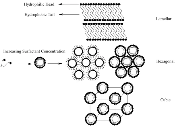
The lyotropic liquid crystals (LLC) can be obtained by mixing surfactant and water (as solvent). The surfactants have dual character and so called as amphiphilic molecules, which have both hydrophilic (affinity for water) and hydrophobic (affinity for oil) parts. The surfactants are surface-active molecules, which reduce the surface tension of the solvent [39]. As a result, the surfactants adhere to the solvent surface [39]. Water is the main solvent used. The surfactants have dual character (Figure 2) because the non-ionic surfactants have long alkyl chains (tails) which is hydrophobic and a hydrophilic polyoxyethylene (-CH2CH2O-, POE) head group.
Figure 2. Various types of surfactants
R O O O O O O O OH O S R O O O -Na + H H N+ R H Cl -Cationic Anionic Non ionic
There are various kinds of surfactants as shown in Figure 2. They can be classified as anionic, cationic, amphoteric and non-ionic based on the type of their head group. The anionic and cationic surfactants are electrolytes and they give the charge to the adsorbed surface and align alkyl group away from the surface.
If a surfactant is added to water, the amphiphilic surfactant molecules orient themselves at the air/water interface. In order to reduce water-hydrocarbon interaction, the hydrocarbon tail orients itself toward air [35-39]. As a result, addition of surfactant reduces the surface tension of water until a point where it stays constant. Adding more surfactant will cause phase separation like benzene-water mixture. However neither complete phase separation nor molecularly dispersed solution occurs. The surfactant molecules self-assemble to create a micro phase in which the hydrocarbon chains sequester themselves inside the aggregate and the polar head groups orient themselves toward the aqueous phase. This is the point where micellisation is discerned and is called critical micelle concentration (CMC). As shown in Figure 3, theaddition of surfactant to the solvent first produces dissolved surfactant molecules and upon increasing the surfactant concentration leads to formation of micelles. Further increase in surfactant concentration leads to the ordered mesostructures.
Figure 3. General lyotropic liquid crystalline phases, formed when a solvent and amphiphilic macromolecules are mixed.
The surfactants form reverse micelles (head group inside the micelle) in organic solvents, and micelles (head group outside the micelle) in polar solvents. Such phases are characterised by having some physical properties of both crystalline and fluid structures. These phases will have at least one dimension, which is highly ordered and, as a result, will exhibit relatively sharp x-ray diffraction patterns and optical birefringence.
Lamellar
Hexagonal
Cubic Increasing Surfactant Concentration
Hydrophilic Head Hydrophobic Tail
Figure 4. Schematic phase diagram for C16TMABr in water [40].
The amphiphilic molecules are associated physically not chemically [35-39], so that they can change the size or shape of their microstructure in response to small changes in concentration, salt content, temperature, pH, and pressure. Therefore, it is possible to get different kind of mesophases and mesostructures by changing the surfactant concentration and/or temperature, see Figure 4 [40].
1.3. Mesoporous Inorganic Materials
Porous materials have very important features due to their micro structures, which enable to obtain high surface area. As a result, these materials may get enhanced catalytic activity and adsorption capacity. A lot of research has done to tailor the pore size and shape. Many mesoporous materials have been synthesized [41] in different pore-size and shape regimes, (see Table 1).
Table 1. Pore-size regimes and representative porous inorganic materials [41].
The zeolites with three-dimensional microporous framework structures are known for a long time. The frameworks forming the channels and the cavities are constructed from linked tetrahedra with many elements, which form MO4 in their structure (M = Al,
Si, P, Be, Ga, Ge, Zn). The different ways in which these tetrahedra are connected produce different type of three-dimensional crystalline frameworks and so form different zeolites. Due to the periodic structure of these crystalline solids, they exhibit an extremely narrow pore size distribution and are very important in size-selective catalysis
[42], ion exchange (water softener in detergents) [43], desiccation, sorption [43] etc. For example, zeolite films are used as stable gas-separation inorganic membranes and sensors [44]. Also the use of zeolite frameworks has been extended to application as nanoreactors [18] in the host-guest chemistry. These zeolites modified with various metals and semiconductors (nano-scale inclusion chemistry) have potentials in electronic and optical applications [44]. Typical areas of applications are: [45] 1) selective adsorption of large organic molecules, 2) catalysis such as processing of tar sand, and 3) the high distillates of crude oils to valuable low-boiling products.
There has been growing interest in the extension of microporous size dimensions and the applications of zeolites to mesoporous size-regimes. Therefore, there have been studies to carry the crystallinity and well–defined pore size distribution of zeolites to the mesoporus regime by using quaternary ammonium salts [46-47]. However, these attempts did not give desired results. Pillaring clay minerals [48], has been used as a method to synthesize mesoporous materials. The clays are naturally occurring three-layer sheet silicates. The structure of these clays has a net negative charge resulting from substitution either the tetrahedral (Al3+, Fe3+ for Si4+) or octahedral (Fe2+, Mg2+ for Al3+) sites. The charges are compensated by alkaline or alkaline earth metal ions. These metal ions can be ion-exchanged for larger oligomeric cations [48]. The calcination of the exchanged materials leads to connection of layers by these pillars. The pillaring increases the surface area of the layered clay minerals [42], however majority of the pore size is in micro-porous range due to small size of oligomeric cations.
Recently, Kresge et al. and Beck et al. [49-50] synthesised mesoporous molecular sieves which is named as MCM-41 (MCM stands for Mobil’s Composition of Matter). They have applied a liquid crystal templating approach to synthesise these materials in the hexagonal, MCM-41, cubic, MCM-48 and lamella, MCM-50 forms. Here the template is not small alkyl chain quaternary directing agents, which have been used in the synthesis of zeolites, but self-assembled supramolecular quaternary ammonium ions as shown in Figure 5 [63].
Figure 5. Formation of microporous and mesoporous molecular sieves by using short and long alkyl chains [63].
These long chain quaternary ammonium salts are used as surfactants, which can form various kind of supramolecular assemblies in different water/surfactant ratios. One of the best features of the MCM family is the ability to tailor the pore size and shape.
Using the surfactant with different alkyl chain length leads to mesoporous materials with different pore size and shape [49-50].
There are many mechanisms [41], which have been proposed by different research groups to explain the formation of mesoporous silica framework. The Mobil researchers have proposed the liquid crystalline templating mechanism for first time [49-50]. Two kinds of pathways are assumed (see Figure 6 [41]);
1) the aluminosilicate precursor species occupy the space between a preexisting hexagonal lyotropic liquid crystals (LC) phase and deposited on the micellar rods of the LC phase, (see the LC section).
2) the inorganics mediate the ordering of the surfactants into the hexagonal arrangement, (see next section).
A “charge density model” was later proposed by Stucky et al. [51] based on their X-ray analysis. In this model, the mesophase formation results from strong Coulombic interaction between the surfactant and silicate species at the micelle interface.
A generalized liquid crystal templating mechanism [52] later has been proposed based on electrostatic interaction between a given inorganic precursor (I) and the surfactant head group (S). In this model, the synthesis of MCM type mesoporous materials was based on the condensation of cationic surfactant (S+) and anionic inorganic species (I-). However various charge matching pathways which are (S-I+), (S+X-I+) X= Cl -, Br- or (S-M+I-) M= Na+, K+ are employed to get mesoporous materials [52]. In highly acidic media (pH<2) the silicate species are cationic (I+) but cationic surfactant (S+) can be used to synthesize mesoporous materials because anionic counter ion X- can behave as buffer between the S+ and I+. Therefore X- mediates formation of mesoporous silica. The resulting materials are known as “acid prepared mesostructures” or SBM materials [41,52]. The SBM-1, for cubic, SBM-3, for 2D hexagonal and SBM-2, for 3D hexagonal structures have different pore wall thickness and framework charge due to different precipitation conditions compared with base-derived mesoporous materials. The SBM-2 is the regularly caged mesoporus silica, however the other mesoporus silica structures posses uniform pore channels but not cages [53].
In contrast to the charge matching methods, the mesoporous materials have also been synthesised using neutral templates [54]. This method is based on hydrogen bonding and self-assembly between natural primary amine micelle (So) and neutral inorganic
precursor (Io). In contrast to the previous methods SoIo pathway allows facile recovery of the template by a simple solvent extraction. Natural alkyl amines are costly and toxic and consequently they are not suited to large-scale synthesis of mesoporous structures. The non-ionic poly ethyleneoxide, CnH2n+1(CH2CH2O)mOH, (PEO) surfactants are used to
mediate the mesoporus structures [55]. The PEO type surfactants are biodegradable and also offer synthetic versatility. In this method, it is possible to prepare mesoporous metal oxides that are not accessible by electrostatic templating method. The metal alkoxides that readily hydrolyze to the corresponding metal oxide can be templated by PEO type nonionic surfactants [55].
The lyotropic liquid crystalline phase as a templating media was first used by Attard et al. [56] for the synthesis of mesoporous silicates. Here, the sol-gel synthesis of the inorganic nanostructure takes place in the ordered environment of a bulk surfactant mesophase. The polycondensation of water-soluble silicates confined within the aqueous domains of a microphase-separated medium yields monolithic mesoporous silicates. This method has an advantage of having a high degree of control over the structure. These monolithic silica materials are large crack-free objects. The continuous silica films with large cage and pore structures have been synthesised [57-58] by poly(ethylene oxide)-block-poly(propylene oxide)-poly(ethylene oxide) triblock copolymers. It is possible to extend the pore size up to 300 Å [59] and get various type of mesoporous structure [60] by changing the type of copolymer. Note also that the PEO type surfactants and amphiphilic block copolymers enabled to synthesise [61-62] mesoporous TiO2, ZrO2,
The EO units in the surfactant complex with inorganic ions through weak coordination, and forms a mesoscopic structure [61-62].
Both sol-gel derived oxides and oxide molecular sieves are usually prepared from oxide gels. In a certain sense, both can be regarded as sol-gel derived oxides, differing only in their degree of structural ordering [63-64]. In sol-gel derived oxides, neither the oxide framework nor the pore structure is ordered. The mesoporous oxide molecular sieves have ordered and uniform pores. As shown in Figure 7, the hydrolysis and then polymerisation-condensation reaction produce amorphous oxide framework. However usage of supramolecular structure directing agents produce well ordered structures with adjustable pores.
Figure 7. Hydrolysis and polymerization-condensation reactions of silica alkoxide.
The hybrid mesoporous materials have also been synthesised to change the properties of bare mesoporous materials [65-66]. These hybrid organic-inorganic groups can be inside the inorganic framework [65] or over the pore wall [66].
OR Si OR OR OR + H2O OR Si OH OR OR + ROH Hydrolysis OR Si OH OR OR + HO Si OR OR OR O Si O O O O Si O O + H2O Condensation
Polymerization-condensation reactions can be acid or base catalyzed and both pathways gives different structures and pore sizes [65-66]. Adjusting reaction conditions can give desired materials. Also functionalizing the pore walls of the mesoporous structures gives many materials with unique properties [67]. The functionalization may be done by co-condensation of original silica source, tetraethoxysilane, with derivatives of silanes [67] or through ion exchange [68]. There are numerous reports that concern the modification of the internal surfaces of MCM type materials with a variety of metals and non-metals. These composite materials can open new areas for application. For example MCM-41 modified with nano-structured Si [69], CdSe [70], or GaN [71], may have application in optoelectronic devices. The mesoporous materials modified with LiCF3SO3 [72], shows high ionic conductivities at room temperature. The Ag
nanoclusters in mesoporus [73] materials show drastic changes in optical properties.
Now, for the synthesis of better molecular devices and nanoelectronics, chemist faced with extension of mesoporous materials beyond the oxides. The synthesis of metal sulfides is still not developed very well. The problem is mainly in the method of synthesis, because the reaction of metal precursors with H2S is fast and does not allow
controlling the morphology and the particle size. The first LC templated CdS, which has been synthesized in the presence of non-ionic surfactant, [74-77] gave hexagonally ordered mesostructure. The syntheses of microporous metal sulfides have also been reported [78-79]. However, these used LC templating methods have some drawbacks, like low metal ion concentration. Therefore, new methods are essential in order to improve the materials quality and property.
1.4. Liquid Crystalline Phase; Template for Inorganic Materials
Designing new molecular materials with novel properties is a newly growing scientific and technological area [1]. The templating step is crucial in order to be able to make materials with desired shape and size. In template based synthesis, inorganic materials copy the shape and the size of the organic template [80]. The organic templates enable to manipulate the microstructure at molecular level, such as biomaterials [81] semiconductor materials synthesised in phosphatylcholine vesicles, nano reactors, [82] and lamellar liquid crystalline phase [83]. In a newly growing area, the 3D photonic crystals, [84] silica colloidal crystals have been used as a template to replicate interstitial void space, in the form of high refractive index materials. As stated in the previous sections, the liquid crystalline phase is used as a template for sculpting and shaping mesoporous materials [41,49-50,52-53,55,58,74-77].
The organic template is a building block and forms a network. It directs the structure of the inorganic material during the synthesis. This ordered network has periodic voids. If it is possible to carry the polymerisation and condensation reactions of the inorganic precursors in these voids, it allows to mimic the shape and size of organic building block. Removing organic template from inorganic matrix leaves porous inorganic material in desired shape and pore size. There are several factors that are important [40] to copy the template: (1) the nature of the interaction between the template and embedding matrix, (2) the ability of the matrix to conform to the template, (3) the relative sizes of the template and the primary units used to construct the matrix.
Figure 8. Lyotropic liquid crystalline phases used as structure directing media (Template) [109a].
The supramolecular surfactant molecules form aggregates when mixed with solvent. These aggregates (micelles) produce the liquid crystalline (LC) phase. In the LC phase templating approach, see Figure 8 [109], the inorganic precursor polymerizes or the reaction takes place in the polar region of the template. Therefore, inorganic matrix mimics the shape and the size of LC phase, depending on which type of LC phase is used. The interactions between the surfactant and the inorganic precursors, depending on the surfactant type, can be electrostatic (if anionic or cationic surfactant is used) or hydrogen-bonding type (if non-ionic surfactant is used) [85]. Also changing the length of alkyl group of the surfactant molecule changes the sizes of the miceller rods, therefore it is possible to change the pore size of the inorganic material. However, this templating method is mostly applicable to the synthesis of mesoporous silica [41,49-50,52-54] and also other metal oxides [61-63]. In order to be able to synthesise other inorganic materials, such as metal sulfides in desired size and shape, new templating methodologies should be developed.
In this thesis, for the first time, we demonstrate that the LC phase of non-ionic surfactants can be formed using aqua complexes of transition metals. In this content, the second component, water, which is the solvent in lyotropic LCs, is replaced by coordinated water molecules. Unlike of the free water molecules, the coordinated water molecules organize the surfactant molecules into more stable structures (hexagonal and cubic). The LC behaviour of the non-ionic surfactant, C12H25(CH2CH2O)10OH, in the
presence of Ni(II), Co(II), Cd(II), and Zn(II) and the formation of mesoporous CdS and ZnS have been demonstrated. These structures (cubic and hexagonal) template the synthesis of mesoporous metal sulfides.
2.EXPERIMENTAL 2.1.Materials
All chemicals and solvents were reagent grade and used as received without any further treatment.
The surfactant used throughout this work, homogeneous polyoxyethylene 10 lauryl ether (C12E10), is commercially available from Sigma, Germany. Cobalt (II) nitrate
hexahydrate (Co(NO3)2·6H2O, 98 % pure) , cobalt(II) chloride hexahydrate (CoCl2·6H2O,
98 % pure) and hydrogen sulfide (H2S, 99.5 %pure) were obtained from Aldrich,
Germany. Nickel (II) nitrate hexahydrate (Ni(NO3)2·6H2O, 97 % pure), zinc (II) nitrate
hexahydrate (Zn(NO3)2·6H2O, 99 % pure) and cadmium (II) nitrate tetrahydrate
(Cd(NO3)2·4H2O, 99 % pure ) were obtained from Merck, Germany.
2.2. Synthesis
2.2.1. Synthesis of liquid crystal phase of inorganic salts
All samples were prepared by direct mixing the surfactant, C12H25(CH2CH2O)10OH (represented No), and metal complex salts (Co(NO3)2·6H2O,
CoCl2·6H2O, Ni(NO3)2·6H2O, Zn(NO3)2·6H2O, and Cd(NO3)2·4H2O, (which are denoted
salts, in mole ratios of (MX2/No); 0.1-7.0. Then, the mixture was either heated up to
isotropisation temperature of the sample or dissolved in acetone which can be pumped out under vacuum to obtain homogenous mixtures. However, most of the samples used through out this work were prepared by heating over the melting point and shaking constantly then cooling to room temperature (RT). This heating and cooling cycles were repeated several times to achieve homogeneity. Finally, the samples were kept below their isotropisation temperature (IT) for several hours. However over heating, especially in the case of (Cd(NO3)2·4H2O) samples, may destroy the desired liquid crystal (LC)
phase.
The surfactant-water-metal salt samples were prepared by mixing 50:50 wt % of water and surfactant (1gr water, 1gr surfactant) and then CoCl2·6H2O),
(Co(NO3)2·6H2O)) and (Ni(NO3)2·6H2O) salts are added to this mixture with a MX2/No
mole ratio 0.0-5.0. The same procedure, which was applied to the water free samples, was used to homogenize the samples.
2.2.2. Synthesis of CdS and ZnS
First, the liquid crystal phase, containing Cd(NO3)2·4H2O and Zn(NO3)2·6H2O
complexes have been prepared as described above. The thin films of the LC phases were prepared on quartz substrates and then these samples were exposed to H2S gas in a
specially designed, evacuated glass cell. (Figure 9). This gives CdS and ZnS film samples over quartz substrates. Another pathway is that the samples prepared in a shlenks
(Figure 9) can be purged with H2S gas under vacuum. Then, the samples were washed
with ethanol-diethylether solution several times to remove unreacted complexes and the surfactant molecules. To collect the products, the ethanol-diethylether solutions were centrifuged and the products were dried at RT.
Figure 9. Glass cells, used in the synthesis of metal sulfides. The cell A used for the synthesis of thin film samples on a quartz substrate and the cell B (shlenk) used for large quantities.
2.3. Instrumentation
2.3.1. Polarized Optical Microscopy
Polarized optical microscopy (POM) has been applied to characterize the mesophases formed from MX2/No mixtures. The LC phases were most of the time
identified by a birefringent texture observed under POM. The samples for the POM
images were prepared by sandwiching the LLC samples in between two glass slides, and heating it above its IT, and then cooling to RT.
The POM images were recorded in transmittance mode on a Meije Techno ML9400 series Polarising Microscope with reflected and transmitted light illumination, using covergent white light between parallel and crossed polarisers. The thermal properties of the mixtures were studied using a Leica Microscope Heating Stage 350 attached to the above microscope. The hot-stage was operated with 3 oC/min heating rate. The attached hot-stage was calibrated against the melting point of naphthalene, which is 80 oC.
Stereo microscope Stemi 2000 from Carl Ziess Jena GmbH with halogen lamp 6V/10W equipped for bright field and phase contrast was used to record the images. Power of the objective was 10x/0.25.
2.3.2. X-Ray Diffraction
The powder x-ray diffraction, PXRD, patterns were collected on a Rigaku Miniflex diffractometer using a high power Cu-Kα source operating at 30kV/15mA. The samples, which are in the LC phase, were prepared on a 0.5 mm glass sample holder. The PXRD patterns were recorded twice for each sample. The first measurements were carried on a less ordered sample (un-oriented) and the second one was carried using a sample heated up to IT and cooled back to RT to obtain well ordered LC phase
(oriented). This was found to be essential in order to see all diffraction lines. The PXRD patterns of ZnS and CdS powder samples were recorded with a 0.2 mm glass sample holder. All the measurements were recorded using 0.20 theta/min scan rate and 0.01 data interval the 2θ range between 1.0 and 10.0. Between 1.0 and 10.0 2θ, the scan rate was 1.00 theta/min and at higher theta values, the scan rate was 4 theta/min.
2.3.3. FT-IR Spectroscopy
The transmission FT-IR spectra were recorded with a Bomem Hartman MB-102 model FTIR spectrometer. A standard DTGS detector was used with a resolution of 4 cm-1 and 128 scan for all samples. The MX2/No samples were prepared as a thin film over
a Si(100) wafer surface. The samples, MX2:No:H2O, prepared using 50 wt %
water/surfactant were sandwiched between two Si(100) wafers. The IR spectra of the powder CdS and ZnS samples were recorded as KBr pellets. The IR spectra of the powder CdS and ZnS samples were also recorded by preparing colloidal dispersion of the sample with ethanol and by evaporating several drops of this suspension over a Si(100) wafer. The FT-IR spectra of all of the samples were recorded in 200-4000 cm-1 range.
2.3.4. UV-VIS Spectroscopy
UV-Vis absorption spectroscopy was used for characterization and also to obtain information about the electronic properties of the mesostructured CdS and ZnS. The UV-Vis spectra were recorded using a Varian Cary 5 double beam spectrophotometer with
150 nm/min speed with a resolution of 2 nm over the wavelength range from 1400 to 200 nm. The UV-Vis absorption measurements were recorded using thin films of mesotructured CdS and ZnS samples over quartz slides and the MX2 /No samples were
sandwiched between two glass slides.
2.3.5. Scanning and Transmission Electron Microscopies (SEM and TEM)
The TEM images were recorded at 300 kV using a JEOL 3010. TEM specimen of metal sulfide is prepared under ambient conditions by depositing a droplet of ethanol-metal sulfide suspension on to carbon films supported on copper grid.
The SEM images were recorded at 16 and 25 kV using a JEOL 6400. The SEM specimen of the metal sulfide is prepared under ambient conditions by depositing a droplet of ethanol-metal sulfide suspension onto a gold coated silica wafer.
3.RESULTS AND DISCUSSIONS
CHAPTER 1
3.1.1. Lyotropic Liquid Crystalline (LC) Phase Behavior of Poly(oxyethylene) Type Nonionic Surfactants with Transition Metal Aqua Complexes as a Second Component.
We have studied the liquid crystal (LC) phase behavior of different transition metal aqua complexes, MYx.nH2O (M= Co2+, Ni2+, Cd2+, Zn2+, Fe2+,) (Y= NO3-, Cl-,
SO42-, CH3COO-), with polyoxyethylene type nonionic surfactants (No). The mixing of
MYx.6H2O with No, depending on the concentration range and type of counter ion, has
produced a new phase. It is well known [35-36] that amphiphilic molecules form lyotropic LC phase depending on amphiphile concentration in water solution. Here, water molecules are the second component for such LC phases. The lyotropic LC phase occurs, because the oil-like tail group (in this work, C12H25-) of the surfactant tends to minimize
the interaction with water and forms micelle in diluted water solutions. However, the polar EO groups (-(CH2CH2O)10OH) tend to stay outside the micelle. Usually, the metal
complexes were added to the media as a third or forth component of the mixture [74-77, 83,86-87]. In such systems, the LC phase is obtained by using water, where the
polar-apolar interactions organise the structure and determine the structure type. In these studies, it is widely accepted that metal salts dissolve in the water (polar) region.
This approach has also produced numerous solid materials with mesoprous structures. It is well established that, for example, the polymerization of silica species takes place in polar region of the LC phase and the final product is the cast of the LC structure [56]. This method has also been used to synthesise various inorganic solid materials [88-89]. Here the LC phase is a structure-directing agent (template). However, in all these procedures, there is a well-known problem. The addition of electrolytes to the pre-constructed LC phase would affect the shape of micelles and mostly reduce the stability of the LC phase [90-95].Therefore dilute concentrations of metal salts have been used in the synthesis of mesoporous CaPO4, CdS, ZnS, [74-77,83] by preserving the LC
phase [96-97]. Attard et al. has shown a stabilisation of the LC phase in the presence of hexachloroplatinicacid (HCPA) as the third component [98]. Again in this study, the LC phase was constructed from free water, and salt concentration was very low [98].
The inorganic electrolytes can be classified into two groups [99-100] according to their effect on mutual solubility of water and No. The first, lyotropic, reduces the mutual solubility between surfactant and water (salting out effect) such as Cl- and SO42- ions; and
the second hydrotropic, increases the mutual solubility between the surfactant and water (salting in effect) such as NO3- and ClO4- ions [99-100]. This effect had been first studied
by Hofmeister more than a century ago [101]. According to his observations the mutual solubility is decreased by the electrolyte (inorganic solids) in the order of; SO42->HPO4
2->CrO4->CO32->Cl->Br->NO3->I-> ClO4->SCN-. These additives reduce or increase the
hydrophilicity of the surfactant. The studies on discontinuous cubic [102] and hexagonal [103] phases revealed that the addition of NaCl reduces the melting and cloud point (reduction of stability) of the LC phase. This is believed to be due to dehydration of the polyethylene oxide (EO) chain. Also note that lyotropic salts cause the effective cross-sectional area per one surfactant molecule to shrink in hexagonal phase due to dehydration of EO chain. However, if NaSCN is added, the melting point shows almost no change at low concentrations but decreases at higher concentrations [102-103]. In addition it is well known that [104] some electrolytes make water a better solvent (structure breakers) and some make water a poorer solvent (structure makers) for EO chain. The structure breakers disrupt the association of water molecules and the structure makers enhance it as shown below:
nH2O (H2O)n
The structure breaking anions [91] I- and SCN-, have low electronegativity, high polarizability and weak electrostatic fields, therefore they disrupt the structure of water and “salt in” the surfactant. However the SO42- and PO43- anions have high
electronegativity and low polarizability therefore they “salt out” the surfactant [91].
In this work, we demonstrate the construction of a LC phase directly from metal aqua complexes. The coordinated water molecules mediate the formation of the LC phase. It is well known [105] that crown ethers can form different kind of hydrogen
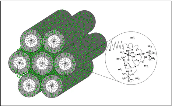
bonding with the metal aqua complexes, as shown in Figure 10. Our surfactant molecule has an EO chain, that acts like crown ethers, forms hydrogen bonds with metal aqua complexes. This interaction organises the surfactant molecules into hexagonally ordered rods that build the LC hexagonal structures, illustrated in Figure 10.
Figure 10. Representation of structure of LC phase formed directly with metal aqua complexes by the help of hydrogen bonding.
We observed the same trend as it is given in Hofmeister series. The Cl-, SO42- and,
H3CCOO-salts of metal complexes did not produce the LC phase with the surfactant.
These salts are lyotropic and reduce the hydrophilicity of the EO chain of the surfactant. Therefore, the solubility of these metal complexes in surfactant is very low and the mixtures undergo complete phase separation (as pure surfactant and complex crystals). However, the LC phase can be constructed with water in the presence of a very low concentration of the transition metal salts of lyotropic anions. Because of high
concentration of free water, these salts dissolve in the water region and the LC phase can tolerate small amount of these lyotropic anions. However, there is no free water used, in our systems therefore such lyotropic counter anion effects on hydrophilicity of EO chain can be directly observed. No mutual solubility of the Cl-, SO42- and, H3CCOO- salts of
these transition metal hexahydrate complexes is observed. However, the metal nitrates are hydrotropic salts, and they increase the solubility. Therefore, relatively high solubility between No and MYx.nH2O has been observed. Due to the hydrogen bonding between the
coordinated water and No, the LC phase is constructed. In contrast to the previous works, we have increased the salt concentration. In addition, we observed a higher LC phase stability with an increasing salt concentration up to a saturation point.
In the Fe(NO3)3.nH2O/No systems, the LC phase is not stable in that the oxidative
reduction of EO chain [106] with Fe(III) ion takes place. Due to low hydrophilicity of EO chain by Cl-, SO42- and, H3CCOO- counter ions; the salts of metal aqua complexes were
excluded from this study. However, CoCl2.6H2O is an exception, because it undergoes
dehydration followed by dimerization reaction and forms CoCl42- ion. In this complex,
the counter ion is no longer Cl- but is CoCl42-. The CoCl42- ion also behaves similarly to
the NO3- ion. Upon mixing CoCl2.6H2O with No, one observes a sharp color change from
reddish pink to blue, which is a good indication of CoCl42- ion [107].
The LC phase behaviours of Co(NO3)2·6H2O, Ni(NO3)2·6H2O, Zn(NO3)2·6H2O,
CoCl2·6H2O and, Cd(NO3)2·4H2O salts with polyoxy ethylene type nonionic surfactant
3.1.2. Polarised Optical Microscopy (POM) and Thermal Properties
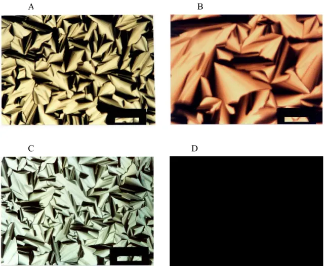
The polarised optical microscopy (POM) is a very powerful tool in the determination of the structure of liquid crystals. An optical texture generated by liquid crystals and other mesophases enables us to identify the structure type. Anisotropic mixtures or materials have different indices of refraction in different directions. This birefringence allows us to see different textures for different anisotropic LC samples. For example, a hexagonally ordered LC phase produces a focal conic fan texture between cross polars, and cubic phase does not produce any kind of a texture. The POM images obtained between cross polars of this phase are completely black (no light passes through the analyzer of the microscope) Figure 11.
The POM images of most of the samples studied in this work show very similar textures. In the Ni(NO3)2.6H2O, Co(NO3)2.6H2O, and CoCl2.6H2O samples, we observed
focal conic fan texture, Figure 11, between 1.2 and 3.2 MX2/No mole ratios. This is an
indication of a hexagonally ordered LC structure. Above this concentration range, the mixtures undergo crystallization. Depending on the metal complex, the crystallization starts at different mole ratios. For example, the crystallization starts at 3.4, 3.6, 3.2, mole ratios for Ni(NO3)2.6H2O, Co(NO3)2.6H2O, and CoCl2.6H2O, respectively. At higher
concentrations of these complexes, the LC phase is still present, but it is mixed with the salt crystals. However, the fresh samples of higher concentrations may show a homogeneous LC phase but are stable only for several hours. All measurements were recorded 24 hours after preparation.
Figure 11. POM images of (a) Ni(NO3)2.6H2O/No hexagonal, (b) Co(NO3)2.6H2O/No
hexagonal, (c) Cd(NO3)2.4H2O/No hexagonal, (d) cubic phase of Cd(NO3)2.4H2O/No with
a mole ratio of 3.6. The scale bar is 200 µm.
The Zn(NO3)2.6H2O (ZnX2) and Cd(NO3)2.4H2O (CdX2) salts show different
behaviours when compared with the other three metal complexes. They also show a focal conic fan texture, Figure 11, under the POM. The CdX2/No and ZnX2/No mixtures are
optically anisotropic between the ranges of 1.4-3.2 and 1.2-3.4, respectively. The mixtures do not show crystallization above these mole ratios but they are optically isotropic at RT. The ZnX2/No mixture shows LC phase till 5.0 mole ratio. However it is
not very stable, in that it crystallizes within one day.
A B
The CdX2/No mixtures do not show any crystallization up to a 7.0 mole ratio.
However, around the 7.0 CdX2/No mole ratio, the mixture seems to decompose from gel
phase (mesophase) to a liquid phase. The CdX2/No and ZnX2/No mixtures do not show
focal conic fan texture above a 3.0 and 3.2 mole ratio, respectively at RT. They have completely dark appearance, between the cross polars Figure 11, at RT. This may be an indication of a cubic phase. The high viscosity and no fluidity also support this proposal (also see, the section on PXRD).
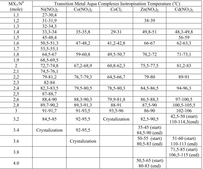
Table 2. Thermal properties and composition of MX2/No mixtures. Start is starting and
end is end point of hexagonal phase.
Transition Metal Aqua Complexes Isotropisation Temperature (oC)
MX2/N0
(mole) Ni(NO3)2 Co(NO3)2 CoCl2 Zn(NO3)2 Cd(NO3)2
1,1 27-30,4 1,2 31-31,9 38-39 1,3 32-34,3 1,4 33,3-34 35-35,8 29-31 49,8-51 48,3-49,8 1,5 45-48,4 56-59 1,6 50,5-51,3 47-48,2 41,2-42,8 66-67 62-63,3 1,7 53,5-55,1 1,8 64,5-67 59-60,8 49,5-50,7 70,2-72 71-73,1 1,9 68,5-69,5 2 72,7-74,8 67,2-68,9 60,8-62,3 75,5-77,5 81,2-83 2,1 74,5-76,1 2,2 79-81,2 76,7-79,3 64,5-66,7 79-80 89-91 2,3 82-84 2,4 82,3-83,5 79,5-80,5 78,5-80,3 84,5-86,5 94-96,3 2,5 87-88,7 2,6 88,4-90 88,3-90,3 79,9-81,8 86,5-88,3 97-100,5 2,8 89,7-90,2 89,3-91,3 88-91 87,5-90 100,5-105,5 3 91-91,7 91-93,5 93,5-96 86-90 102-106
3,2 84,5-85 92-95,5 Crystalization 82,5-90,5 110-114,3(end)42,5-50 (start) 3.4 Crystalization 92-95,5 84,5-90 (end)35-45 (start)
3.6 Crystalization 80,5-83 (end)50-55 (start) 110-113 (end)51-60 (start)
3.8 106,5-115 (end)71,5-85 (start)
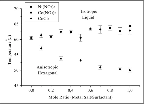
The thermal properties of these lyotropic LC mixtures were determined using a hot stage attached to the microscope. The phase transition, from a LC phase to a liquid phase or from a cubic phase to a hexagonal phase then to a liquid phase, temperatures were determined for a broad range of MX2/No mixtures. Note that the anisotropic
mixtures show optical birefringence between cross polars while the melts are isotropic, which show no texture between the cross polars. The isotropisation temperatures (IT) were determined by watching the disappearance of the characteristic texture, using POM. The ITs for metal complexes studied in this work are given in Table 2. In the table, the first temperature is where anisotropy starts to disappear during heating and the second temperature is where anisotropy starts to appear again during the cooling. The cubic phase starts to appear above 3.0 and 3.2 mole ratio for the CdX2/No and ZnX2/No
mixtures, respectively. This phase is optically isotropic and shows a phase transition to an anisotropic phase. Therefore it is possible to determine the anisotropisation temperature (AT). Above 4 mole ratio for the CdX2/No and ZnX2/No mixtures, only the cubic phase
starts to appear (no hexagonal phase). The cubic phase is optically isotropic, therefore it is not possible for us to determine the phase transition temperatures of these mixtures by using POM.
The ITs show a constantly increasing trend with complex concentrations. This contradicts with previous observations [76,83,91]. The disappearance of the LC phase at high salt concentrations was observed for hydrotropic salts. Note also that, as stated in previous works, [76,91] the addition of hydrotropic salts does not affect the IT a lot, also our observations on the samples, which are prepared with free water show the same
result. However, our new approach, yields stable LC phase until the saturation point. As shown in Figure 12 for Co and Ni complexes the IT increases with increasing MX2/No
mole ratio. For the Ni(NO3)2.6H2O, Co(NO3)2.6H2O, and CoCl2.6H2O salts, the 3.0
MX2/No mole ratio appears to be the saturation point. Note also that there is a small
decrease above this point, and then the crystallization starts.
Figure 12. Temperature profiles for Co and Ni complexes.
The CdX2/No and ZnX2/No mixtures do not show hexagonal fan texture after 3.0
and 3.2 at RT, respectively. Above these mole ratios, the samples are optically isotropic. However, when they are heated, they display a phase transition from the isotropic to anisotropic, which shows a focal conic fan texture, see Table 2. Like other metal complexes, the ITs increase with the salt concentration. Between a 3.0 and 3.6 mole ratio
1,0 1,5 2,0 2,5 3,0 3,5 20 30 40 50 60 70 80 90 100 Isotropic Liquid Anisotropic Hexagonal Ni(NO3)2.6H2O Co(NO3)2.6H2O CoCl2.6H2O Temperature ( o C)
the LC phase has a melting point over 100 oC, which is very high compared with the LC phase prepared by adding the free water and salt as a third component. The ZnX2/No and
CdX2/No mixtures are optically isotropic at all temperature above mole ratios of 4.0 and
3.8, respectively.
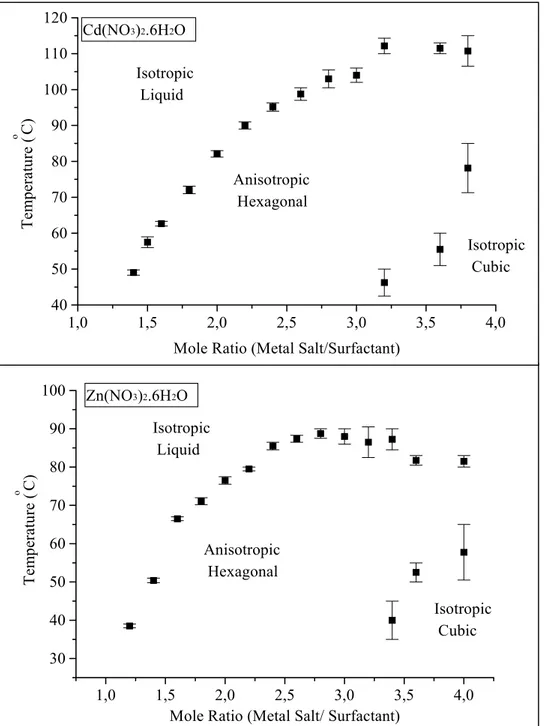
Figure 13. Temperature profiles for Cd and Zn complexes withC12EO10.
1,0 1,5 2,0 2,5 3,0 3,5 4,0 40 50 60 70 80 90 100 110 120 Isotropic Cubic Anisotropic Hexagonal Isotropic Liquid Cd(NO3)2.6H2O Tempera ture ( o C)
Mole Ratio (Metal Salt/Surfactant)
1,0 1,5 2,0 2,5 3,0 3,5 4,0 30 40 50 60 70 80 90 100 Isotropic Cubic Anisotropic Hexagonal Isotropic Liquid Zn(NO3)2.6H2O Tem perature ( o C)
They do not show any phase change. The saturation point is reached at a mole ratio of 5 for the ZnX2/No mixture. However, it is not stable more than 24 hours and
crystallizes within a day Figure 13.
The CdX2/No mixtures do not show crystallization up to a mole ratio of 7, but it
appears that this concentration does not have a LC phase. At these concentrations, the samples are isotropic at RT. Therefore the POM is useless for determining whether there is a mesophase or not. We used powder x-ray diffraction, PXRD, to establish the mesophase and LC behaviour of the high concentrations. It was determined that the CdX2/No shows LC phase behavior up to a 6.5 mole ratio (see text for PXRD). This is a
very high salt concentration compared with the metal ion concentration applied in conventional method [74-77, 83] (the maximum concentration achieved so far is around 0.8 MX2/No mole ratio).
To make our point clear, the LC phase was also constructed in free water (50/50 wt %), then Ni(NO3)2.6H2O or Co(NO3)2.6H2O, or CoCl2.6H2O salt is added to this
mixture. The ITs were recorded in the same way as before. As it is shown in Table 3 and Figure 14, the Ni(NO3)2.6H2O and Co(NO3)2.6H2O salts have very little effect on the
isotropisation temperature. The LC phase surfactant/water (50 wt %) has an IT around 60oC. There is only 4-5 oC increase in ITs in a broad range of the salt concentrations.
Because there are many free water molecules in the mixtures, the metal complex are solvated, therefore the surfactant molecules have very little interaction with the metal aqua complexes and all the salt is in free ions form, see text for FT-IR.
Figure 14. Temperature profiles for MX2/No mixtures with free water. The
surfactant/water is 50 wt %. M; Ni(H2O)62+ , Co(H2O)62+ and X; NO3-, Cl-.
Notice also that in the case of Cl- salt, the ITs decrease with metal complex concentration, (Figure 14). Since Cl- is known as a lyotropic anion, which has a “salting– out” effect, it is expected to dehydrate the EO chain. The sample viscosity also decreases with salt concentration, especially around 1.0 mole ratio and the samples become more like a liquid. However, the LC phase, which is directly prepared from metal aqua complexes, becomes thicker with an increasing salt concentration. There is no harm in stating that, if one classifies the LC phase prepared by using free water, as liquid-like, the LC phase prepared directly from metal complex, is crystal-like.
0,0 0,2 0,4 0,6 0,8 1,0 45 50 55 60 65 70 Anisotropic Hexagonal Isotropic Liquid Ni(NO3)2 Co(NO3)2 CoCl2 T em perat ur e ( o C)
Table 3. Thermal Properties of for MX2/No mixtures with free water. The
Surfactant/Water is 50 wt %. M; Ni(H2O)62+, Co(H2O)62+, and X; NO3-, Cl–.
Transition Metal Aqua Complexes ITs Temperature (oC)
MX2/N0-H2O
(mole)
Ni(NO3)2 Co(NO3)2 CoCl2
0,0 60,5 0,1 61,35 57,15 0,2 60,9 0,3 62,5 53,75 0,4 62,4 0,5 60,55 53,2 0,6 63,5 0,7 63,25 50,95 0,8 63,75 0,9 62,7 50,4 1,0 64,35 62,9 50,05
The lyotropic LC phase occurs, because the oil-like tail group of the surfactant tends to reduce the interaction with the water molecules to a minimum and forms micelle in dilute water solutions. On the other hand, the polar EO groups (-(CH2CH2O)10OH)
tend to stay outside the micelle. If one compares the ITs, it is clear that the hydrogen bonding interaction between the coordinated water and surfactant is much stronger than the hydrogen bonding between the free water molecules and the surfactant.
![Figure 1. Representative phase transition, from solid to liquid crystal and then to liquid phase [35].](https://thumb-eu.123doks.com/thumbv2/9libnet/5903515.122232/24.892.185.638.176.418/figure-representative-phase-transition-solid-liquid-crystal-liquid.webp)
![Figure 4. Schematic phase diagram for C 16 TMABr in water [40].](https://thumb-eu.123doks.com/thumbv2/9libnet/5903515.122232/28.892.224.649.162.581/figure-schematic-phase-diagram-c-tmabr-water.webp)
![Figure 5. Formation of microporous and mesoporous molecular sieves by using short and long alkyl chains [63].](https://thumb-eu.123doks.com/thumbv2/9libnet/5903515.122232/31.892.142.727.452.828/figure-formation-microporous-mesoporous-molecular-sieves-using-chains.webp)
![Figure 8. Lyotropic liquid crystalline phases used as structure directing media (Template) [109 a ].](https://thumb-eu.123doks.com/thumbv2/9libnet/5903515.122232/38.892.155.755.153.408/figure-lyotropic-liquid-crystalline-phases-structure-directing-template.webp)