Review Article
Plasmon-Exciton Resonant Energy Transfer:
Across Scales Hybrid Systems
Mohamed El Kabbash,
1Alireza Rahimi Rashed,
1,2Kandammathe Valiyaveedu Sreekanth,
1Antonio De Luca,
3Melissa Infusino,
4and Giuseppe Strangi
1,31Department of Physics, Case Western Reserve University, 10600 Euclid Avenue, Cleveland, OH 44106, USA
2Nanotechnology Research Center, Bilkent University, 06800 Ankara, Turkey
3Department of Physics, University of Calabria, CNR-Nanotec, Licryl Laboratory, 87036 Rende, Italy
4Colegio de Ciencias e Ingenier´ıa, Universidad San Francisco de Quito, Avenida Diego de Robles s/n y Pampite, Cumbay´a,
1712841 Quito, Ecuador
Correspondence should be addressed to Alireza Rahimi Rashed; [email protected] and Giuseppe Strangi; [email protected] Received 28 November 2015; Revised 24 February 2016; Accepted 6 March 2016
Academic Editor: Jorge P´erez-Juste
Copyright © 2016 Mohamed El Kabbash et al. This is an open access article distributed under the Creative Commons Attribution License, which permits unrestricted use, distribution, and reproduction in any medium, provided the original work is properly cited.
The presence of an excitonic element in close proximity of a plasmonic nanostructure, under certain conditions, may lead to a nonradiative resonant energy transfer known as Exciton Plasmon Resonant Energy Transfer (EPRET) process. The exciton-plasmon coupling and dynamics have been intensely studied in the last decade; still many relevant aspects need more in-depth studies. Understanding such phenomenon is not only important from fundamental viewpoint, but also essential to unlock many promising applications. In this review we investigate the plasmon-exciton resonant energy transfer in different hybrid systems at the nano-and mesoscales, in order to gain further understnano-anding of such processes across scales nano-and pave the way towards active plasmonic devices.
1. Introduction
Localized Surface Plasmons (LSPs) are collective oscillations of free electrons localized at metallic surfaces. This phe-nomenon results in a confined and significantly enhanced field compared to the excitation field [1–3]. A relevant phenomenon, Surface Plasmon Polaritons (SPPs) are evanes-cent electromagnetic waves propagating along the interface between a metal and a medium possessing permittivity with opposite sign, for example, a dielectric [4–6]. Although LSPs are not propagating waves like SPPs, they can be used as plasmonic subdiffraction electromagnetic waveguides which can be utilized in building broadband and fast nanocircuitries and devices [7, 8]. In addition, their remarkable optical responses allow the coherent generation of light [9–13], selective sensing of organic and biological markers with very high resolution [14, 15], and imaging at subwavelength scale by beating the diffraction limit [16–18]. The field of
nanoplasmonics is the key to explore “the plenty of room at the bottom” especially with the current advances in top-down and bottom-up nanofabrication techniques.
Surface plasmon resonance occurs at a frequency near the plasma frequency of metallic nanoparticles (NPs) which is a function of the shape and size of the nanoparticles. Due to causality, this strong resonant response is associated with strong damping and losses especially in the visible frequency range, which is the major challenge for most of the future and current applications of plasmonics. Several strategies have been proposed to overcome plasmonic losses problem including highly doped semiconductors [19], using superconducting metals [20], reducing surface roughness [21], and introducing gain in the dielectric surroundings of plasmonic NPs. Using hybrid gain-metal systems was proposed as a possible way to enhance the total internal reflection in the presence of thin silver metal film on a prism [22] and to increase the propagation length of SPPs
Volume 2016, Article ID 4819040, 21 pages http://dx.doi.org/10.1155/2016/4819040
by creating population inversion in the dielectric medium adjacent to the metallic film [23]. Nezhad et al. proposed that the presence of gain in the dielectric medium assists the SPP propagation by compensating for metal losses making it possible for the SPP to propagate with little or no loss on metal boundaries and guides [24]. As discussed by Lawandy in [25], the field enhancement due to LSPs in metallic nanoparticles surrounded by optically active dielectric medium can have a singularity resulting in a huge local field enhancement and an increase in Rayleigh scattering. Experimentally, both loss compensation of SPPs and field enhancement of LSPs were demonstrated [26, 27]. Furthermore, loss compensa-tion in metallic nanoparticles by using active medium was suggested to overcome absorptive losses in metals used as negative index metamaterials for super lensing that requires a lossless medium [28], which has been latter demonstrated experimentally [29]. Stockman in [30] showed that gain-assisted full loss compensation and SPASER (surface plasmon amplification by stimulated emission of radiation) generation share the same conditions which is governed by F¨orster energy transfer between a donor gain molecule and a metal NP acceptor. The essence of many of these ideas lies in the fact that the near field amplification of a lossless metal alone requires no energy input, which in reality cannot be achieved due to losses except by introducing an amplifier that compensate such losses through a near field energy transfer mechanism, that is, EPRET. It is thus extremely important to understand the nature of such processes using different hybrid gain-plasmon systems at different scales.
It is important to note that while the underlying physics is not very complicate, it is sometimes confusing to know whether EPRET is taking place or not due to the peculiar nature of the interaction between metallic nanoparticles and emitters. While being an efficient emitter due to its size, the NP will not emit in the far field due to EPRET unless it fully compensates its losses and enter into a SPASER mode. Accordingly, EPRET should result in a reduction in the emission of the excited chromophore (organic dye molecules or quantum dots (QDs)) due to the nonradiative energy transfer from the exciton to the “dark” surface plasmon, that is, an induced surface plasmon that ends up dissipating its energy in the form of absorption. On the other hand, the emission of emitters located near a metallic NP may increase several orders of magnitude via a nanoantenna effect, resulting in the so called metal enhanced fluorescence (MEF). In both cases, however, we require the overlap between the emission of the excited molecules and the plasmon band and the spatial proximity between the two species, and we expect a reduction in the decay time of the excited molecules. In fact, the physical process that initiates both processes is the same; an excited optical gain with a specific transition dipole moment resonantly induces a surface plasmon in a nonradiative manner which may or may not allow radiative emission in the far field.
The radiating plasmon model was introduced to enable the prediction of the dominant effect [31]. According to this model emission enhancement or quenching of an emitter near a metallic NP can be predicted from the optical prop-erties of the metallic structures. For instance, the extinction
of metal colloids can be either due to absorption or scattering. Incident energy is dissipated by absorption, whereas far-field radiation is out-coupled by scattering. Accordingly, small colloids are expected to quench fluorescence because absorption is dominant over scattering while larger colloids are expected to enhance fluorescence because the scattering component is dominant. This simplistic view, however, is not enough to capture all the physics necessary to distinguish between the two effects. For instance, it has been demon-strated recently [32] that for larger Au NPs the emission intensity of an emitter is quenched more significantly relative to smaller ones. According to this work [32], the increased quenching for larger particles was due to the stronger overlap between the emission spectrum and the plasmon band which strengthened EPRET. Hence, it is instructive to understand that each effect, quenching due to EPRET and enhancement of emission due to MEF, has many parameters that need to be considered in a case-by-case analysis.
Enhancing the emission due to the presence of metallic NPs can be understood from two different and equally valid perspectives. The existence of a NP near an emitter increases the optical density of states, due to the confinement of the emission field in the vicinity of the NP. According to Purcell effect, this means that the radiative decay rate of the emitter should increase due to the decrease in the modal volume, that is, the effective cavity where the mode is confined within [33]. The increase in radiative decay rate, as we will show in detail, leads to a net increase in the emission intensity. Another way to look at the enhanced emission is to think of metallic nanoparticles as efficient antennas that radiate the emission in the far field in a more efficient way compared to small atoms or molecules [34], thus increasing the probability of far field emission for the emitter. From this point of view a larger particle can indeed act as a better emitter, which goes along with the radiating plasmon model.
On the other hand, EPRET is form of dipole-dipole res-onant nonradiative energy transfer first addressed by F¨orster [35] and it is highly sensitive to donor-acceptor interdistance, dipole-dipole orientation, dipole moment strength of both the donor and the acceptor, and dipole-dipole resonance. As all quantum phenomena, resonance energy transfer is a matter of probability. Having dipole-dipole resonance by ensuring a strong spectral overlap between the emission band and the plasmon band increases the probability of energy transfer and has been demonstrated experimentally [36, 37]. This anecdotally depends on the NP’s size, since the plasmon band depends on the size and shape of the particle. Energy transfer probability depends strongly on the interdistance between the NP and the emitter and has been shown clearly in [38]. Intuitively, the size of the NP and the interdistance between the chromophore-NP pair have the same effect on the RET; a close but small NP is just like a big but far one, from the perspective of EPRET. Still a bigger NP works as a better antenna and can reradiate or scatter in the far field more efficiently. In addition, the dipole moment of a large NP is stronger and thus it can strengthen the dipole-to-dipole energy transfer. What we want to say is that making general statements about which effect is dominant is incorrect and
a closer look to all the parameters that govern EPRET and emission enhancement is important.
To that end, we have designed different hybrid gain-plasmon systems that exhibit EPRET and varied several parameters in order to gain deeper understanding of this important phenomenon. We believe that this work highlights important aspects that are necessary in the future design of hybrid systems that can fulfill the full promise of plas-monics. In this paper we discuss the main concepts related to plasmon-exciton coupling in different hybrid structures in order to elucidate the physical parameters governing EPRET and what are the consequences of these near field interactions. Next, we present our work on plasmon-exciton hybrid systems in the nano- and mesoscales. Finally, we will present macroscale systems that exhibit interesting properties that capitalize on plasmon-exciton coupling.
2. Theoretical Background
2.1. Plasmon-Exciton Coupling Mechanisms in Hybrid Plas-monic Nanostructures. The size transition of noble metals from bulk to atomic scale exhibits wide spectrum of inter-esting material behavior. While high conductivity and reflec-tivity are the main characteristics of the bulk noble metals, their particles in size domains comparable or smaller than the incident light wavelength show the fascinating property of the LSPR (Localized Surface Plasmon Resonance), which occurs when the oscillation of LSP resonates with the incident electromagnetic field.
Mie theory expresses a generic solution to extract extinc-tion cross secextinc-tion of spherical particles that can be extended from dynamic regime (mesoscale,𝑅 ∼ 𝜆) into the quasi-static regime (nanoscale,𝑅 ≪ 𝜆) [39]. In dynamic regime, due to significant phase changes of the driving field over the particle volume, the electric field distribution along the particle is nonuniform. Thus, the contribution of multipolar modes in the electrodynamic calculation is considered, whereas in quasi-static approximation, due to the uniform distribution of the electric field along the NP, one can consider that the electron cloud polarization is coherent in each point of the particle and therefore only dipolar plasmon oscillations are excited. Hence, LSPR occurs only in such small particles, in which the particle size is much smaller than the wavelength of the incident light. The quasi-static approximation leads to the following expression for the extinction cross section𝐶ext [39]: 𝐶ext= 24𝜋2𝑟3𝜀3/2ℎ 𝜆 𝜀𝑖(𝜔, 𝑟) (𝜀𝑟(𝜔, 𝑟) + 2𝜀ℎ)2+ 𝜀2 𝑖 (𝜔, 𝑟) . (1)
In this equation,𝜀𝑟+ 𝑖𝜀𝑖is the complex dielectric function of the NP with radius𝑟 and 𝜀ℎis the dielectric constant of the surrounding medium. From (1),𝐶exthas a strong resonance whenever the condition𝜀𝑟 = −2𝜀ℎis satisfied. The brilliant colors of various metal NPs are observed for frequencies that correspond with the LSPR peak. It is clear from (1) that the position, shape, and intensity of the plasmon band strongly depend on several factors such as the metal composition, the size [39], the surrounding dielectric medium [40], and
the shape of the NP [41], as well as NPs arrangement and electronic interactions between the stabilizing ligands with NPs [42].
The decay time of an excited state𝜏Exof a chromophore depends on radiative and nonradiative decay processes:
𝜏Ex= 𝑘 1
𝑟,0+ 𝑘𝑛𝑟,0. (2)
Here,𝑘𝑟,0and𝑘𝑛𝑟,0are intrinsic radiative and nonradiative decay rates of a chromophore, respectively. This is closely related to the quantum yield of fluorescence of such molecule ΦExwhich is a measure of the number of photons emitted for a given number of photons absorbed [43]:
ΦEx= 𝑘𝑟,0
𝑘𝑟,0+ 𝑘𝑛𝑟,0 = 𝑘𝑟,0𝜏Ex. (3) Furthermore, the emission rate𝐾emdepends on the quantum yield, as well as the excitation rate𝑘exc:
𝐾em= ΦEx𝑘exc. (4)
A photo-induced electronic excitation of a chromophore present in close vicinity of a plasmonic nanostructure results in energy transfer from the excited entity (exciton) to the plasmonic modes of a NP or vice versa through nonradiative channels (EPRET process). Moreover, as mentioned earlier, MEF could affect the radiative decay rate of the excited molecules near plasmonic NPs. Hence, the modified decay time (𝜏Ex-NP) and quantum yield (ΦEx-NP) of an exciton near a metallic NP are expressed as follows:
𝜏Ex-NP= 𝑘 1 𝑟,0+ 𝑘𝑛𝑟,0+ 𝑘RET+ 𝑘MEF , (5) ΦEx-NP= 𝑘𝑟,0+ 𝑘MEF 𝑘𝑟,0+ 𝑘𝑛𝑟,0+ 𝑘RET+ 𝑘MEF , (6)
where𝑘MEFis the radiative decay rate due to metal enhanced fluorescence and𝑘RETis the rate of resonance energy transfer (RET) in a plasmon-exciton system separated by a distance 𝑑, in which it is usually analyzed in terms of the following expression: 𝑘RET= 1 𝜏Ex( 𝑅0 𝑑) 𝑚 . (7)
Here in (7), 𝑅0 known as F¨orster radius is the distance at which the RET efficiency drops to 50%. At large separation distances compared to the radius𝑎 of the NP 𝑘RETis F¨orster type, which varies with the inverse sixth power of the separation distance of exciton-plasmon pair (𝑚 = 6), while at small distances (approximately 𝑑 = 𝑎 to 𝑑 = 4𝑎), the value of 𝑚 lies between 3 and 4 [44–46]. It is important to realize the crucial role played by the gain-NP distance in determining which exciton plasmon phenomenon would take place.𝑘RETdepends on several system parameters such as (i) interparticle distance [47], (ii) relative spectral overlap between excitonic emission band and NPs surface plasmon
+ − − + (a) − + + − (b)
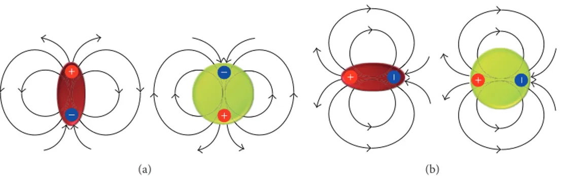
Figure 1: (a) Parallel (tangential) and (b) perpendicular (radial) orientation of chromophore dipole moment to the surface of spherical NP leading to the suppression or enhancement of the radiative decay rate of the exciton, respectively.
band (SPB) [47, 48], (iii) relative orientation of chromophores transition dipole moment with respect to NPs plasmon mode [49], (iv) strength of transition dipole moment [50], (v) the geometry and size of the metal nanostructures [51, 52], and (vi) concentration and molar extinction coefficient of the plasmonic and excitonic particles [53]. However, the most significant factor that affects the rate of this process is the plasmon-exciton separation distance.
For very small distances, Dexter Energy Transfer (DET) process dominates. This process is very similar to EPRET in the sense that it results in an increase in the nonradiative decay rate of the exciton, yet it is fundamentally different in terms of the underlying physics. DET occurs due to the physical overlap between the wave functions of the donor exciton and acceptor NP that results in electron transfer which is translated into energy transfer much like charge transfer due to adhesion that causes static charge accumulation. Accordingly, this process takes place when the interdistance is of approximately 10 ˚A. This is true for conventional FRET processes as well as for EPRET; however, in the case of plasmonic NPs, no experimental evidence has been reported for the approximate interdistance where DET dominates.
In addition, as we discussed formerly, for longer sepa-ration distances in the order of 20–30 nm and depending on the size and plasmonic resonant frequency, MEF process may dominate the interaction, because of the weak coupling Purcell effect. The study of Bhowmick et al. shows that the effect of interparticle distance over the rate of energy transfer is associated with the particle size [54]. The expression of F¨orster radius reveals how𝑘RET is correlated with the other above mentioned factors:
𝑅0= 0.211 [𝑘2⋅ 𝑛−4⋅ ΦEx⋅ 𝐽 (𝜆)]1/𝑚 [ ˚A] , (8) where 𝑛 is the refractive index of the medium and 𝐽(𝜆) represents the overlap integral between the emission spec-trum of the exciton and the absorption specspec-trum of the plasmonic particle. The parameter 𝑘2 is the orientation factor, which represents the influence of the excitonic dipole orientation relative to the plasmonic resonant dipole. Due to the symmetric shape of the spherical NPs, the dipole-dipole relative orientation dependence of EPRET process is significantly different than that of the FRET case, where we
have two chromophores as a donor and acceptor pair [54]. In the case of the FRET, if the dipoles of the donor and acceptor are perpendicular to each other, RET process is forbidden, while it is maximum, if they are parallel to each other. However, in the case of EPRET, by assuming that the NP is symmetric, when plasmon and exciton dipoles are perpendicular to each other, the RET reaches its minimum rate but does not get to zero. Therefore, in the EPRET process, there is no particular orientation where EPRET is forbidden. Furthermore, according to [54] as the distance gets smaller, the effect of the relative orientation of the exciton dipole moment and the NP becomes less significant for shorter distances. Intuitively, this could be understood by taking into consideration the huge size of the NP compared to a dye molecule. In fact, for short distances the NP would block the horizon of such a small molecule and then a change in the dye’s dipole orientation would become less significant.
On the other hand, MEF is very sensitive to the relative orientation of the exciton and the NP. Experimental and theoretical studies show that the net luminescence can either quench [55] or enhance [56] the emission depending on the orientation of exciton-plasmon dipoles [54, 57, 58]. In the case of parallel (tangential) orientation of chromophore dipole moment to the surface of the NP, the induced dipole of the NP and the chromophore dipole will radiate out of phase which will decrease total radiative decay rate (𝑘𝑟,0 + 𝑘MEF) (Figure 1(a)) [59]. Taking into account that EPRET will not be affected drastically by the relative orientation of the two dipoles, according to (6) this will result in quenching the emission. On the other hand, when the chromophore dipole is perpendicularly (radially) oriented towards the NP (Figure 1(b)), the dipoles’ radiation field will constructively interfere and thus MEF, as well as total radiative decay rate, will increase. It should be noted that in this case EPRET also will be taking place and other parameters will determine whether emission will be quenched or enhanced [38, 50].
It is worth noting that for both MEF and EPRET processes another effect takes place; the short living excited states decrease the possibility of photobleaching, as well as other interactions that may result in destroying the fluorescent nature of the chromophores, resulting in the increase in their photostability. In addition, this effect increases the molecules excitation rate, since more excited molecules are now knocked down to the ground state and ready to absorb
and participate in the emission process. This results in an enhancement in the total emission rate, according to (4).
Another closely related effect is the lightning rod effect and it takes place when the absorption band of the chro-mophore overlaps with the plasmon band of the NP which acts as a receiver nanoantenna that confines the electromag-netic field which effectively increases the excitation rate of the chromophore and thus increases the total emission rate𝐾em according to (4). The enhancement of the local field due to plasmonic confinement has gained much attention and used to be the main focus of research since it resulted in many promising applications such as Surface Enhanced Raman Spectroscopy SERS [60], enhancing nonlinear optical effects [61], and magnetooptical effects [62], as well as in enhancing the absorption cross-section of semiconductors, in order to increase their efficiency for photovoltaic applications [63] in which usually they suffer from the high band gap with respect to the solar spectrum. It is easy, for most cases, to distinguish between lightning rod effect and MEF effect, since the latter requires the overlap of the emission band of the chromophore with the plasmon band of NP. Furthermore, the lightening rod effect will not change the life time of the excited state.
Concentration of the chromophores plays an important role in determining the efficiency of the EPRET process. The right concentration of the chromophores can be determined by considering the size, shape, and molar concentration of plasmonic particles [64].
The plasmon-exciton interactions of hybrid systems can be investigated by acquiring static fluorescence intensity, time-resolved fluorescence spectroscopy, and quantum yield of chromophore molecules. The plasmon-induced fluores-cence time decay(𝐼(𝑡)) of a hybrid system, measured via time correlated single photon counting (TCSPC), can be fitted by a multiexponential decay function:
𝐼 (𝑡) =∑𝑛 𝑖=1
𝛼𝑖exp(−𝑡
𝜏𝑖) , (9)
where𝜏𝑖are the decay times and𝛼𝑖represent the amplitudes of components at 𝑡 = 0. By means of the quantum yield measurement the total radiative decay rate (𝑘𝑟), total nonradiative decay rate (𝑘𝑛𝑟), and𝑘RET components can be obtained by given equations:
𝑘𝑟= ΦEx-NP 𝜏Ex-NP , 𝑘𝑛𝑟= 1 − ΦEx-NP 𝜏Ex-NP , 𝑘RET(𝑟) = 1 − ΦEx-NP 𝜏Ex-NP −1 − ΦEx 𝜏Ex . (10)
Plasmonic NPs are not ideal resonators as they exhibit high ohmic losses, particularly in optical wavelengths. Accordingly, having a low value of the imaginary part of the dielectric permittivity is important for realizing many plasmonic applications. In fact, the problem of optical losses in plasmonic nanostructures must be tackled before moving towards the fabrication of functional devices. To that end,
theoretical [65–67] and experimental studies [68–70] have demonstrated that EPRET processes can play a role in modi-fying the imaginary part of the effective dielectric function of such hybrid systems, which can pave the road towards high efficiency optoplasmonic devices.
2.2. Plasmon Hybridizations Theory. Plasmon resonances and in general the extinction spectra of the geometrical complex metal nanostructures such as metallic nanoshells and multimeric nanostructures can be predicted by means of plasmon hybridization model [71–73]. According to the plas-mon hybridization theory the plasplas-mon response of metal-based nanostructures can be viewed as the collection of plas-mons arising from simpler geometries to form an interacting system. Accordingly, for a composite system that consists of several interacting surface plasmons, the resulting resonance is a superposition of plasmon oscillation eigenstates in a manner equivalent to hybridization of molecular orbits in molecular orbital theory.
For a spherical core-shell particle plasmon hybridization approach predicts two divided plasmon oscillation modes𝜔𝑙− and𝜔𝑙+ consisting of a sphere𝜔sp and cavity𝜔𝑐 plasmons. Due to the finite thickness of the shell layer, the sphere and cavity plasmons interact with each other and hybridize in a way analogous to the hybridization between atomic orbitals (Figure 2(a)). The 𝜔𝑙− mode corresponds to “bonding” or the lower energy symmetric coupling between the sphere and cavity modes, while𝜔𝑙+mode corresponds to the higher energy antisymmetric or “antibonding” plasmon mode [71]. The antisymmetric mode is located at higher frequencies with respect to the symmetric mode, since higher level of excitation energy, that is, higher frequency, is needed to polarize oppositely the different surfaces of the metal shell.
The strength of the hybridization between the sphere and cavity plasmons of a nanoshell is determined by the difference in their energies𝜔spand𝜔𝑐as a function of metallic shell thickness; the thinner the shell the bigger the energy difference between the two modes (Figure 2(b)). This should not come as a surprise since a higher frequency is required to create the antisymmetric mode as the shell thickness decreases since we have less retardation time between the sphere and cavity modes.
A multimeric nanostructure composed by attaching individual NPs has different plasmon modes relevant to a single NP. According to the plasmon hybridization theory the fundamental plasmon modes of multimeric systems can be expressed as linear combinations of multipolar plasmon modes of individual NPs. The strength of the hybridization depends on the arrangement of single NPs in a multimeric nanostructure [74].
Plasmon modes of a dimer can be viewed as bonding and antibonding combinations, that is, hybridization of the plasmons of two individual NPs. The dimer plasmon energies can be varied as a function of dimer separation for plasmon polarizations along the dimer axis. In a dimer with large interparticle distance, the plasmons of two NPs interact only weakly. The plasmon hybridization theory can be extended to calculate the electromagnetic response of multimeric systems with arbitrary symmetry such as trimers and quadrumers.
+ + + + + − − − − − 𝜔sp= 𝜔√3B 𝜔c= √23𝜔B 𝜔l− 𝜔l+ + + + + + + + ++ −−−− − − − − − − + − + − + − + (a) 𝜔l− 𝜔l+ 𝜔c 𝜔sp 𝜔c 𝜔sp 𝜔l+ 𝜔l− (b)
Figure 2: (a) Energy level diagram representing plasmon hybridization in metal nanoshells resulting from interaction among sphere and cavity plasmons. The two hybridized plasmon modes are an antibonding plasmon (𝜔𝑙+) and a bonding plasmon resonance (𝜔𝑙−). (b) Illustrating the dependence of the nanoshell’s plasmon resonance energies on the strength of the interaction between the sphere and the cavity’s surface plasmons, determined by the thickness of the metallic shell. Regenerated with permission from reference [72].
The plasmon modes of each configuration can be considered as symmetry-specific linear combination of plasmons of the individual NPs, by applying group theory [75].
3. Hybrid Plasmon-Exciton
Systems across Scales
3.1. Exciton-Plasmon Resonance Energy Transfer at the Nanoscale. Plasmon-exciton coupling is a phenomenon that pertains mainly to the nanoscale. Here we select differ-ent hybrid systems that highlight some of the important parameters that affect the plexciton coupling process. The advancement in nanochemistry allowed us to go beyond the traditional free gain/plasmonic systems to gain control over different coupling parameters and enabled us to selectively investigate each physical parameter.
3.1.1. Gain-Functionalized and Gain-Assisted Plasmonic Sys-tems. The exciton-plasmon resonance energy transfer, as discussed earlier, depends on the separation distance between NPs and dye molecules. This dependence manifests itself when we compare the properties of assisted and gain-functionalized core/silica shell. The main difference between these two systems is that in the gain-assisted system flu-orescent guest molecules are mixed in solution with the plasmonic nanoparticles, whereas NP gain functionalization comprises “smart nanoparticles” carrying built-in gain ele-ments obtained by incorporating optically active components (quantum dots or organic dyes) within the silica shell [76].
We have used a gain-assisted system that consists of Au core/silica shell nanospheres (core diameter 60 nm, silica shell 30 nm) dispersed in an ethanol solution of Rhodamine 6G (R6G). To synthesize gain-functionalized system, the
Au Silica shell R6G Au R6G R6G 520 560 600 640 680 720 760 800 480 Wavelength (nm) 0.0 0.2 0.4 0.6 0.8 1.0 In te n si ty (a.u .) fluor. emission absorp. Au-Nps plasmon band
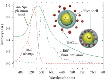
Figure 3: Absorption (red dashed line) and emission (blue dash-dot line) spectra of R6G dye in ethanol and plasmon bands of gain-assisted gold nanoparticles (green solid line), including schematics of gain-assisted and gain-functionalized systems. Reprinted with permission from [76].
same parameters were used as in the gain-assisted system; however, the R6G molecules were not present freely in the ethanol solution; rather they are embedded inside the silica shell. As compared to the assisted system, the gain-functionalized approach allows a fine control of key parame-ters such as dye-metal core interdistance and dye concentra-tion, offering the advantage of clearing inactive fluorescent molecules from solution. Figure 3 shows a schematic for both gain-functionalized and gain-assisted core-shell systems as well as the absorption and emission bands of R6G and the plasmon band.
Decay_R6G Fit_R6G Decay_Gain_Assisted Fit_Gain_Assisted Decay_Gain_Funct. Fit_Gain_Funct. 10 100 1000 L og co un ts (a.u .) 1000 1500 2000 2500 3000 500 Decay time (ns) (a) 𝜏 ∼ 5.4 ns 𝜏1∼ 190 ps 𝜏2∼ 6 ns 𝜏 ∼ 120 ps 400 800 1200 1600 2000 L og co un ts (a.u .) 22 23 24 25 26 27 21 Decay time (ns) (b)
Figure 4: (a) Time-resolved fluorescence intensity decays: GA and GF systems are compared to pure R6G dye solution. Emission decay of pure R6G (red dots) characterized by a single time constant𝜏fluo= 5.4 ns. The decay dynamics of the GA system (blue dots) exhibit two decay time components representing the fast and short living excited states which are identified. A single short-living emission is identified for GF indicating a strong dye-NP coupling (pink dots). (b) Zoom image of the time-resolved fluorescence decays. Reprinted with permission from reference [76].
To demonstrate EPRET, fluorescence life time mea-surement experiments were conducted on ethanol solution of pure R6G molecules, assisted system, and gain-functionalized systems. Figure 4 reports the time correlated single photon counting (TCSPC) data for the three systems. For the free dye system the fluorescent life time decay was fitted as a single exponential function giving a time constant of𝜏fluo= 5.4 ns. For the gain-assisted system (blue dots and cyan line fit), two components can be identified in the decay dynamics. For the gain-assisted system (blue dots and cyan line fit), two components can be identified in the decay dynamics: a fast decay time of𝜏𝐴1= 190 ps and a long-living emission of𝜏𝐴2 = 6 ns. The first decay time is attributed to the fraction of dye molecules decorating the silica shell that experience a stronger resonant energy transfer process, while the long-living emission is related to the fraction of unbound dye molecules (the largest fraction) present in solution but that are not coupled to plasmonic nanoparticles. Strikingly, the time-resolved spectrum of the gain-functionalized system (pink dots) shows only a short-living intensity emission decay, fitted as a single exponential with a time constant (𝜏𝐹= 120 ps). Accordingly, this decay time can be attributed to the encapsulated fluorescent molecules resonantly coupled to the plasmonic gold core. It is worth noting that in the gain-functionalized system there is no long-living emission due to unbound R6G molecules. Thus, the identification of a single-exponential decay of the short-living encapsulated dye emission indicates a complete and effective exciton-plasmon coupling.
Another important study [77] utilizes gain functionaliza-tion approach in order to control for the concentrafunctionaliza-tion and
the average distance separation between dye molecules and plasmonic NPs in order to probe other parameters. In this study two different dyes C500 and DCM that have different spectral overlap with the plasmon band, (Figure 5) were used to decorate gold core/silica shell nanoparticles to create two gain-functionalized systems of GF-DCM and GF-C500.
As mentioned earlier, (7) shows that the radiative energy rate 𝑘RET is inversely proportional to decay time. This is mainly due to the inverse relation between the decay time of dye molecules and the strength of their transition dipole moment. Fluorescence lifetime measurements for free molecules and gain-functionalized NPs are shown in Figure 6 and tabulated in Table 1.
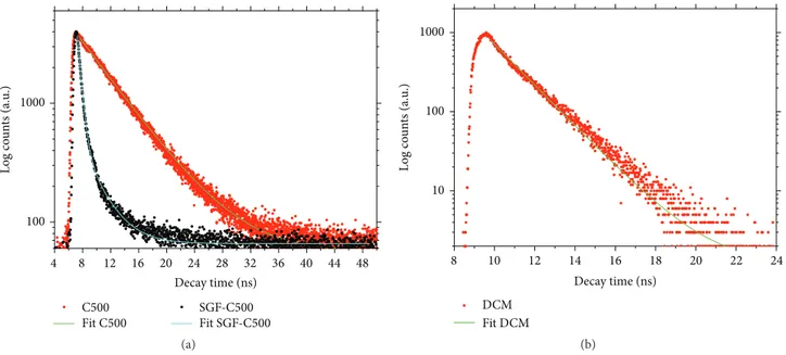
The fluorescence decay time of free DCM dye molecules is found to be five times smaller than that of the C500. For the gain-functionalized systems, the C500 system exhibits two decay times, a short decay time reflecting the EPRET nonra-diative energy transfer and a longer decay time representing the fluorescence of the uncoupled dye molecules. Strikingly, the gain-functionalized DCM exhibits complete fluorescence quenching with no emission measured. While the spectral overlap for DCM is less than that of C500, the strength of EPRET is much stronger for DCM than C500, which can safely be attributed to the strength of its transition dipole moment.
3.1.2. Active Plasmonic Multimeric Systems. Multimeric nanostructures are promising nanostructures that show how hybridization of plasmon modes can result in a net enhancement of the local field for plasmonic nanostructures and thus strengthen the plasmon-exciton coupling [78]. This
Table 1: Time resolved fluorescence decays for GF-C500 and GF-DCM systems with respect to the pure dye solutions.𝜆exand𝜆emstand for excitation and emission wavelengths, respectively.𝜏1and𝜏2are the components of the biexponential function used to fit the acquired TCSPC data.𝜒2is the chi-square function which shows the goodness of the applied fit. Reprinted with permission from [77].
Sample 𝜆ex(nm) 𝜆em(nm) 𝜒2 𝜏1(ns) 𝜏2(ns) C500-ethanol 265 498 0.997 5.42 ± 0.01 GF-C500 265 498 0.998 2.78 ± 0.05 0.508 ± 0.003 DCM-ethanol 379 626 0.995 1.682 ± 0.005 GF-DCM 379 626 — No emission No emission Au Wavelength (nm) Abs_C500 Emission C500 800 700 600 500 400 0.0 0.2 0.4 0.6 0.8 1.0 In te n si ty (a.u .) (a) Au Wavelength (nm) Abs_DCM Emission DCM 770 700 630 560 490 420 350 0.0 0.2 0.4 0.6 0.8 1.0 1.2 In te n si ty (a.u .) (b)
Figure 5: (a) Absorption (red dash) and emission (blue dash dot) spectrum of C500 dye dissolved in ethanol and plasmon band (black line) of GF-C500 gold NPs. (b) Absorption (red dash) and emission (blue dash dot) spectrum of DCM dye dissolved in ethanol and plasmon band (black line) of GF-DCM gold NPs. Reprinted with permission from reference [77].
Decay time (ns) 1000 100 L og co un ts (a.u .) C500 Fit C500 SGF-C500 Fit SGF-C500 48 44 40 36 32 28 24 20 16 12 8 4 (a) Decay time (ns) 1000 100 10 L og co un ts (a.u .) DCM Fit DCM 24 20 22 16 18 12 14 8 10 (b)
Figure 6: Time-resolved fluorescence intensity decays and corresponding fits of (a) GF-C500 and (b) GF-DCM systems in comparison to pure dye solutions of C500 and DCM, respectively. Reprinted with permission from [77].
(a) (b) Wavelength (nm) Abs_Mo+10 Abs_Mo+30 Abs_Mu+10 Abs_Mu+30 RhB emission RhB absorption 1.00 0.98 0.96 615 600 585 570 555 450 800 750 700 650 600 550 500 450 0.0 0.2 0.4 0.6 0.8 1.0 N o rm alized extinc tio n (c)
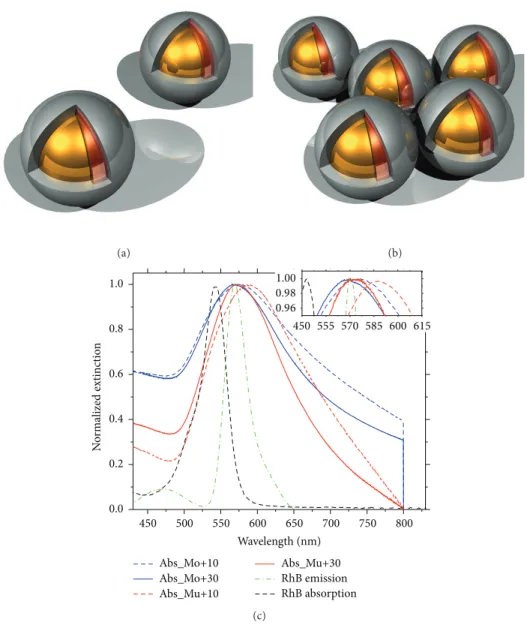
Figure 7: Sketches of the active (a) monomers and (b) multimers. (c) Extinction spectra of active monomers and multimers, including absorption and emission spectra of RhB dye molecules. All samples are dispersed in ethanol. Reprinted with permission from [78].
is one main reason why, as mentioned earlier, the EPRET depends on the geometry and configuration of the hybrid nanostructure.
We have compared the plasmonic behavior of gold core/silica shell doped with Rhodamine B isothiocyanate (RhB) monomeric structures with 10 nm (Mo+10) and 30 nm (Mo+30) shell thickness, and multimeric samples, that is, controlled conglomerations of two or more monomers, prepared from both Mo+10 (Mu+10) and Mo+30 (Mu+30) samples. The sketches of monomeric and multimeric systems are provided in Figures 7(a) and 7(b), respectively. As shown in Figure 7(c) the surface plasmon peak for multimers is red-shifted with respect to monomers.
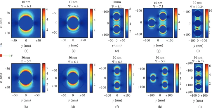
In addition, simulation results presented in Figure 8 showed that the net field enhancement intensity of multi-meric samples is stronger than monomulti-meric samples. Finally,
as the silica shell thickness decreases the local field is further enhanced for multimeric samples. This can be understood using plasmon hybridization model. As discussed earlier plasmon hybridized modes lead to the splitting of the plasmon resonances into lower energy symmetric plasmon and the higher energy antisymmetric plasmon. As the gap between NPs decreases the coherent (symmetric) mode is more pronounced with respect to the antisymmetric one, since the response delay of the electron charge density is minimized. The presence of such a strong coherent mode results in a stronger field intensity, as well as lower reso-nance energy of the bonding mode, since the coherence is maximized by having a slower amplitude variation, that is, frequency, which results in a red-shift of the plasmon peak. This explains the correlation between stronger field intensity
y (nm) y (nm) y (nm) y (nm) (a) (b) (c) (d) (e) (f) (g) (h) (i) (j) y (nm) y (nm) y (nm) y (nm) y (nm) y (nm) Ψ = 6.110 nm Ψ = 6.410 nm Ψ = 8.110 nm Ψ = 7.110 nm 10 nm 30 nm 30 nm 30 nm 30 nm 30 nm Ψ = 5.7 Ψ = 6.1 Ψ = 6.3 Ψ = 5.9 z (nm) z (nm) −50 0 +50 −50 0 +50 2 4 6 8 −50 0 +50 −100 0 +100 2 4 6 −50 0 +50 −50 0 +50 1 2 3 4 5 −100 0 +100 −100 0 +100 2 4 6 −100 0 +100 −100 0 +100 1 2 3 4 5 −50 0 +50 −50 0 +50 2 4 6 −50 0 +50 −50 0 +50 2 4 6 −100 0 +100 −100 0 +100 2 4 6 Ψ = 10.24 Ψ = 6.35 −100 0 +100 −100 0 2 4 6 8 10 −100 0 +100 2 4 6 0 −100 +100 −200 +200 +100 y x z
Figure 8: Simulation results for local field of monomers and multimers with 10 nm silica shell thickness of (a) passive monomers; active (c) monomers, (e) dimers, (g) trimmers, (i) aligned trimers, and 30 nm silica shell thickness of (b) passive monomers; active (d) monomers, (f) dimers, (h) trimmers, and (j) aligned trimers. The normalized field profiles (Ψ) have been plotted in the 𝑦-𝑧 plane. Reprinted with permission from [78].
Table 2: Time-resolved fluorescence decay results for monomeric and multimeric systems with 10 nm and 30 nm fluorophores-NP separation distances.𝜆exand𝜆emstand for excitation and emission wavelengths, respectively.𝜏1,𝜏2, and𝜏3are the components of the tri-exponential function used to fit the TCSPC data correlated to each one of active sample.𝜒2is the chi-square function which shows the goodness of the applied fit. Reprinted with permission from [78].
System 𝜆ex(nm) 𝜆em(nm) 𝜏1(ps) 𝜏2(ps) 𝜏3(ns) 𝜒2
Mu+10 375 572 70 ± 1 332 ± 3 3.00 ± 0.01 1.27
Mo+10 375 572 88 ± 2 971 ± 56 2.90 ± 0.01 1.14
Mu+30 375 572 325 ± 7 1582 ± 40 5.32 ± 0.01 1.18
Mo+30 375 572 452 ± 10 1860 ± 20 3.2 ± 0.1 1.07
and the observed red-shift in the plasmon resonance peak of multimeric systems.
The main observations are that (i) nonradiative RET processes occur between chromophores and metal cores leading to very short life times (𝜏1); (ii) EPRET process is drastically affected by their separation distance; (iii) as a result of plasmon hybridization process, multimeric systems generally create more intense plasmonic hot spots (high local fields), providing stronger plasmon-exciton coupling with respect to monomeric systems; (iv) the intermediate decay times (𝜏2) indicate that the decrease of silica shell thickness, as well as enhanced local fields, further promotes indirect couplings, irrespective of monomeric or multimeric systems. The enhancement of the net confined field intensity indeed increases the strength of the EPRET. Table 2 summa-rizes the results of Figure 9 of the time-resolved fluorescence spectroscopy of the mentioned systems.
3.2. Exciton-Plasmon Resonance Energy Transfer at the Mesoscale. Plasmonic structures in the mesoscales offer a
very important step towards utilizing the interesting plas-monic properties in macroscopic applications. Here, we deal with two systems, mesocapsules and gold nanoshells (GNS). 3.2.1. Gain-Assisted Plasmonic Mesocapsules. We have used mesocapsule systems [79] that consist of porous silica shells with a radius of∼800 nm embedding plasmonic nanoparti-cles in a dye doped solution with R6G (see the schematic of Figure 10). These pores allow dye molecules to infiltrate the capsule. Figure 10(b) shows the plasmon band of mesocapsule structures which is wider and red-shifted with respect to that of single nanoparticles. This can be explained by using the plasmon hybridization theory, as well.
The fluorescence decay time shows a change in the decay time for higher mesocapsule concentrations with respect to the free R6G molecules (Figure 11(a)) of the same concentra-tion showing how using the right NP to dye concentraconcentra-tion plays an important role in ensuring the occurrence and strength of EPRET. Another and more compelling evidence on the coupling occurrence is obtained by measuring the
L og co un ts (a.u .) 2.1 2.4 2.7 3.0 3.3 3.6 Time (ns) 2 4 6 8 0 10 12 14 16 18 20 Time (ns) 101 102 103 104 4 × 10³ 6 × 10³ 8 × 10³ 104 RhB Mo+10 Fit Mo+10 Mu+10 Fit Mu+10 (a) L og co un ts (a.u .) 101 102 103 104 2 4 6 8 0 10 12 14 16 18 20 Time (ns) 2.1 2.4 2.7 3.0 3.3 3.6 Time (ns) 4 × 10³ 6 × 10³ 8 × 10³ 104 RhB Mo+30 Fit Mo+30 Mu+30 Fit Mu+30 (b)
Figure 9: Time-resolved fluorescence decays and relative fitting plots of (a) monomer (Mo+10) and multimer (Mu+10) systems. (b) Monomer (Mo+30) and multimer (Mu+30) systems. Reprinted with permission from [78].
Au NPs R6G (a) Extinc tio n cr oss s ec tio n 500 550 600 650 700 450 Wavelength 0.0 0.2 0.4 0.6 0.8 1.0 Fl uo . emissio n (a.u .) 1.00 1.05 1.10 1.15 1.20 1.25 1.30 1.35 (b)
Figure 10: (a) Schematic of a plasmonic mesocapsule. (b) Mesocapsule plasmon band (black continuous line) and R6G emission spectrum (red dashed line). Reprinted with permission from reference [79].
fluorescence quenching efficiency calculated as𝑄 = 1−𝐹/𝐹0, where𝐹 and 𝐹0are the fluorescence signal intensity of the dye in the presence and the absence of the quencher, respectively. Figure 11(b) plots𝑄 versus pump power, that is, the number of excited dye molecules. It is clear that the dye molecules emission in mesocapsules does not increase proportionally with respect to free dye molecules, which means that there is a strong nonradiative EPRET. Indeed, this assumes that mesocapsules are static quenchers; that is, their absorptivity is not a function of the pump power.
Unlike gain-functionalized structures, dye molecules in mesocapsules are quite dispersed and are not in close proxim-ity to the plasmonic acceptor. However, the strength of meso-capsules in fostering EPRET comes from the homogeneity of the electric field inside the capsules. As discussed earlier, the orientation of the gain dipole moment plays an important role in optimizing the energy transfer. The dye molecule dipoles minimize their energy if they reoriented themselves inside the mesocapsules due to the homogeneity of the electric field, which enhances the net dipole moment of the gain molecules.
−45 −40 −35 −30 −25 −20 −15 −10 −5 0 Δ𝜏 (%) 0.5 1.0 1.5 2.0 0.0 R6G concentration (mg/mL) C1-S3 C2-S3 (a) 5 10 15 20 25 30 Pump power (mW) 80 82 84 86 88 90 92 94 96 Quenc hin g efficienc y (%) C2-S3 (b)
Figure 11: (a) Percentage decrease of the fluorescence decay time versus dye concentration for two different concentrations of mesocapsules (𝐶1 = 1.25 mg mL−1;𝐶2= 7.5 mg mL−1). (b) Fluorescence quenching efficiency as a function of the pump energy, calculated by using the acquired fluorescence maxima of gain-assisted system of R6G (𝐶𝑟= 1.2 mg mL−1) and mesocapsules at concentration of𝐶2in ethanol solution versus the fluorescence maxima of corresponding R6G solution. Reprinted with permission from [79].
This emphasizes the importance of strategically positioning the gain with respect to the geometry of plasmonic structures.
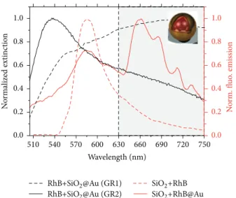
3.2.2. Plasmonic Active Nanoshells. Metal based nanoshells consist of spherical particles with diameters that can reach up to 250 nm in diameter and are composed of dielectric core (usually SiO2) covered with a thin gold shell; these structures can be considered in the mesoscale; however, their name is derived from the nanoscale shell thickness [80, 81]. Plasmonic nanoshells have very interesting optical properties that make them very attractive on their own for many applications, especially bioimaging and photothermal therapy, since they are biocompatible and have strong optical cross section and luminescent properties [82–84]. The EPRET for Au nanoshells was studied by preparing SiO2 dielectric core (∼170 nm) covered with a thin gold shell of ∼20 nm thickness doped with RhB dye molecules [85]. Figure 12 shows the plasmon band of the Au nanoshells, as well as the emission of RhB embedded inside SiO2beads and while being embedded inside the core of Au nanoshells. The emission of embedded RhB dye molecules in the Au nanoshell is quenched, while the intrinsic luminescence originating from the structure of nanoshells accounts for the extra peaks.
The EPRET is evident from fluorescence decay time results presented in Figure 13 for dye-doped nanoshells as compared to that of doped RhB in SiO2beads. The schematic of the used setup to perform ultrafast fluorescence decay time spectroscopy is shown in Figure 14(a). Metallic nanoshells importance in bioimaging depends on its ability to scatter incident fields, while its photothermal therapy applications capitalize on its absorbance, while these properties can be
tuned by reducing the metallic shell thickness to get stronger absorbance, or increasing the shell thickness to get stronger scattering.
EPRET, however, can provide a way to enhance absorp-tion and scattering simultaneously within the visible spec-trum. As mentioned earlier, EPRET changes the imaginary component of the electric permittivity which is directly related to the absorption of the plasmonic structure. Using a pump-probe setup (shown in Figure 14(a)) the normalized transmission difference was measured for different pump power. Evidently, as the pump power increases, resulting in activating more dye molecules, the system’s absorbance is enhanced in the optical range 530–610 nm and it decreases in the 630–750 nm range (see Figure 14(b)), while the scattering remains unchanged. This offers new possibilities toward optical tuning of the plasmonic properties in the mesoscale.
3.3. Exciton-Plasmon Resonance Energy Transfer at the Macroscale. The realization of tangible metamaterials that can exhibit strong EPRET on the macroscale is quite chal-lenging. However, we present two different techniques that provide a promising step towards realizing such goal: a bottom-up approach using microfluidic techniques and a top-down approach using hyperbolic metamaterials.
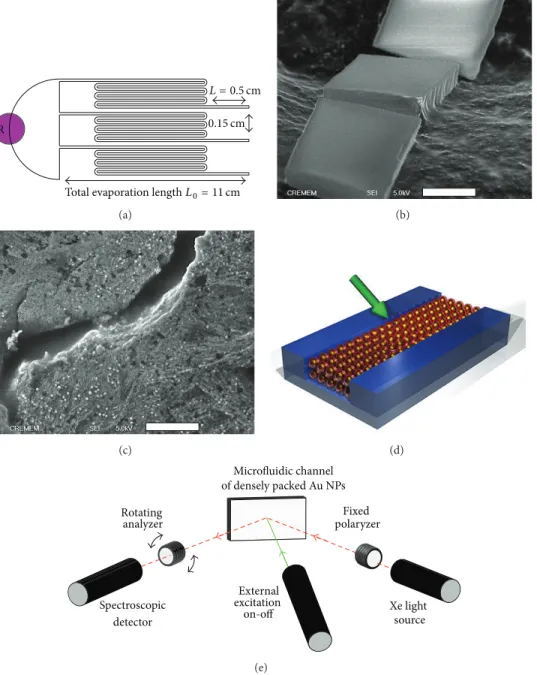
3.3.1. Exciton-Plasmon Resonance Energy Transfer Using Microfluidic Systems. Microfluidic technique allows concen-trating NPs to create a bulk structure, by injecting microflu-idic channels with a dilute mixture containing NPs (Fig-ure 15(a)) [86]. Since microchips are made out of elastomer,
Wavelength (nm)
510 540 570 600 630 660 690 720 750
RhB+SiO2@Au (GR1)
RhB+SiO2@Au (GR2) SiO2+RhB@Au
SiO2+RhB 0.0 0.2 0.4 0.6 0.8 1.0 N o rm alized extinc tio n 0.0 0.2 0.4 0.6 0.8 1.0 N o rm. fl u o . emissio n
Figure 12: Normalized extinction cross section of dye doped nanoshells with the two gold growths (dashed and continuous black curves) and emission of dye doped silica beads SiO2+RhB (red dashed curve) and nanoshell of SiO2+RhB@Au (continuous red curve). 𝜆exc = 400 nm, including the schematic of a dye doped metallic nanoshell. Reprinted with permission from reference Normalized extinction cross section of dye doped nanoshells with the two gold growths (dashed and continuous black curves) and emission of dye doped silica beads SiO2+RhB (red dashed curve) and nanoshell of SiO2+RhB@Au (continuous red curve). 𝜆exc = 400 nm, including the schematic a dye doped metallic nanoshell. Reprinted with permission from reference [85].
it is permeable to water and other solutions but not NPs. Subsequently, we can selectively extract the solvent while injecting the channels with more solvent, allowing for the NPs to accumulate, forming bulk crystal like 3D structure (see Figures 15(b) and 15(c)). The EPRET was studied by using a metal gold core (diameter∼ 12 nm) covered by a silica shell (∼12 nm thickness) doped with DCM gain molecules. To extract the macroscopic physical quantities, the authors used variable angle spectroscopic ellipsometry VASE implemented with an external pump source (Figure 15(d)). Ellipsometry measures the complex reflectance ratio (𝜌) of a system, which may be parameterized by the amplitude component (Ψ) and the phase difference (Δ). The incident probe light can be decomposed to 𝑠 and 𝑝 polarization components. The amplitudes of the𝑠 and 𝑝 components after being normalized are denoted by𝑟𝑠and𝑟𝑝, respectively.𝜌 is defined as the ratio between𝑟𝑠and𝑟𝑝and thus is equal to tan(Ψ)exp(iΔ), where tan(Ψ) = |𝑟𝑠|/|𝑟𝑝| is the amplitude ration upon reflection and (Δ) = 𝛿𝑟𝑝− 𝛿𝑟𝑠is the phase shift.
The plasmon band measurement was performed by mea-suring the transmission (Figure 16(a)) of a 1 mm solution in a cuvette; the plasmon resonance peak is around 532 nm. When the microfluidic procedure is followed, a 3D bulk structure of gain-functionalized nanoparticles is formed. Figure 16(b) shows the spectroscopic behavior ofΨ as a function of the incident light. The plasmon peak shows a collective resonance shift about 530 nm due to the plasmon hybridization caused by aggregation of nanoparticles. 5 10 15 20 25 30 Time (ns) 101 102 103 104 Lo g10 (co un ts) 4 × 10 3 8 × 10³ Deca y 8.0 8.5 6.5 7.0 7.5 5.5 6.0 5.0 Time (ns)
RhB+SiO2@Au (fit result) RhB+SiO2@Au (counts)
SiO2+RhB (fit result) SiO2+RhB (counts)
Figure 13: Time-resolved fluorescence spectroscopy results of RhB molecules, doped in silica (red dots) and embedded in silica core of nanoshells (black squares), together. The inset shows a zoom image of the time-resolved fluorescence decays. Reprinted with permission from [85].
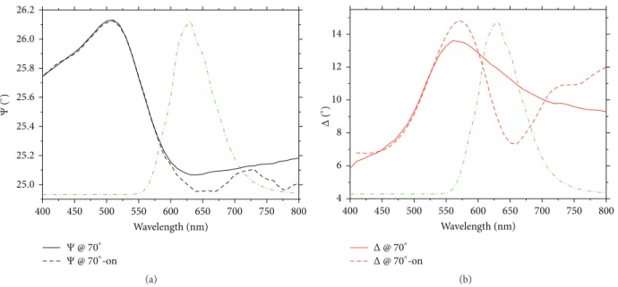
Figures 17(a) and 17(b) show the behavior of bothΨ and Δ as a function of wavelength at a specified angle of 70∘with the pump source switched off (solid line) and on (dashed line). Interestingly, in the spectral region where plasmon band and emission band overlap (see green dash-dot curve in Figure 17(a)), we find a strong modification ofΨ and Δ curves (black and red dashed curves in Figures 17(a) and 17(b), resp.) while pumping the material with respect to the absence of excitation.
On the other hand, no modification is observed for the ellipsometric parameters at the excitation wavelength (532 nm) but is observed only in spectral region where gain and plasmon bands overlap. This different optical response is the result of a change in the physical properties of bulk materials induced by a resonant energy transfer process. The exciton-plasmon coupling ensured by the designed topolog-ical and spectral configuration dominates the mechanism of conveying excitation energy nonradiatively into the plasmon states.
3.3.2. Plasmon-Exciton Coupling in Hyperbolic Metamaterials. In this section, we demonstrate the plasmon-exciton coupling in hyperbolic metamaterials. Hyperbolic metamaterials [88] feature hyperbolic dispersion, because one of their principal components has the opposite sign to the other two. Their properties include strong enhancement of spontaneous emis-sion, extremely sensitive biosensing, diverging density states, negative refraction, and enhanced super-lensing effects. [19, 89–91]. They are characterized by optical hyperbolic isofre-quency surfaces with a diagonal form of the permittivity tensor𝜀 = diag(𝜀𝑥, 𝜀𝑦, 𝜀𝑧), in which diagonal elements have
D1 D2 CCD MCP Xe 𝜆/2 𝜆/2 𝜆/2 P P P M M FM FM FM PE PE PE BC H2 H1 3D mov. SHG module Super con. generation Pulse picker BS Line1 Line2 Ti:S pulsed laser (a) 510 540 570 600 630 660 690 720 750 Wavelength (nm) −0.6 −0.4 −0.2 0.0 0.2 0.4 0.6 0.8 1.0 N o rm. del ta tra n smissio n 400 nm)
RhB+SiO2@Au (Emission, Ex@
RhB+SiO2@Au (plasmon band)
(b)
Figure 14: (a) Ultrafast spectroscopic setup with the two distinct lines dedicated to decay time and pump-probe measurements. (b) Delta transmission as a function of average excitation power (from 5 mW to 200 mW, every 10 mW). Double behavior observed in the two spectral regions 510–630 nm (decreasing) and 630–750 nm (increasing). Here vertical axis is the difference between the broadband transmitted intensities of the probe beam in presence and absence of the exciting beam (pump), normalized to probe beam intensity in the absence of pump beam. Reprinted with permission from reference [85].
different signs (𝜀𝑥 = 𝜀𝑦 and 𝜀𝑥 ⋅ 𝜀𝑧 < 0) leading to the hyperbolic dispersion as following equation:
𝜔2 𝑐2 = (𝑘2𝑥+ 𝑘2𝑦) 𝜀𝑧 + 𝑘2 𝑧 𝜀𝑥. (11)
Such metamaterials support high-wave vector propa-gating waves (bulk plasmon polaritons (BPPs) modes) due to hyperbolic dispersion [92]. As discussed earlier, SPPs are delocalized surface plasmons that couple a photon in a dielectric (called polariton) to the surface plasmons on a metal interface. These SPPs are evanescent waves in the direction normal to the metal-dielectric interface, across which they propagate. The momentum of such surface modes is so high that light incident on such interface cannot be coupled directly and requires either a grating, prism, or scatterers in order to give the necessary momentum “kick.” However, the evanescent field of the SPPs is capable of providing such coupling momentum, as well. The BPPs exist due to coupling of the evanescent fields of several SPPs propagating in a separate but very close metal-dielectric interface. Accordingly, this type of HMMs, called type II HMMs, has a propagating field in the bulk which makes it “look like” a dielectric in the𝑧 direction. However, this propagating mode is extremely confined, since it is a product of coupled evanescent fields. This is the physical origin of the extremely high density of photonic states in HMMs. According to the Purcell effect, one can expect that light would be sucked inside such modes and any emitter that is located on top of HMM surface would increase its emission rate. These modes are also dark modes and do not radiate back in the far field, unless another mechanism is provided to out couple it [93–95].
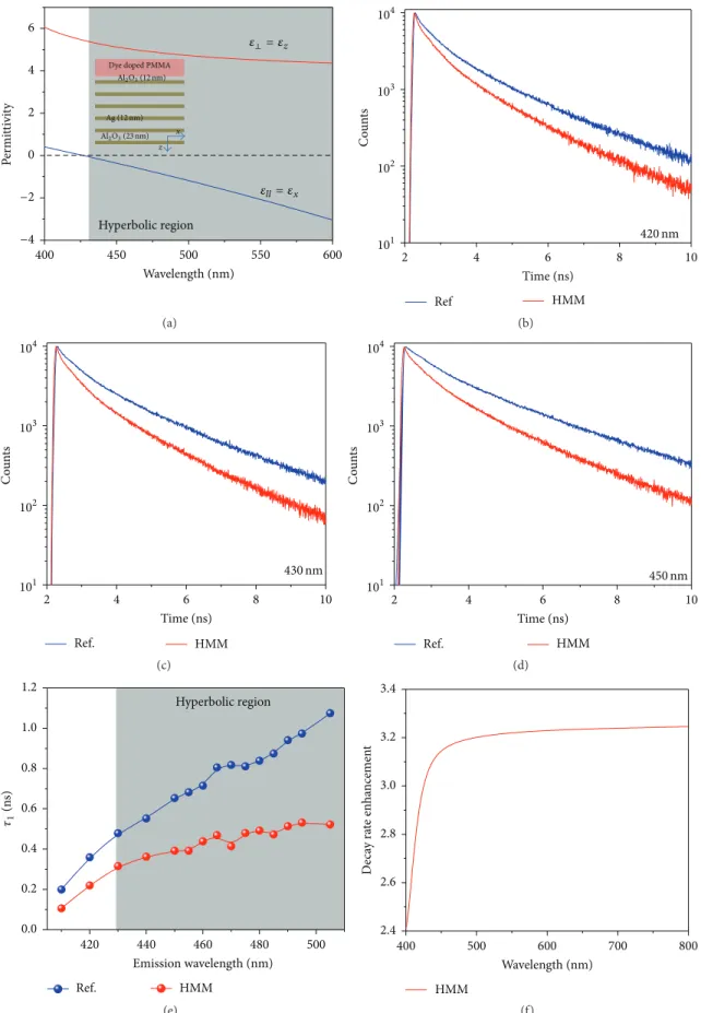
We have performed time-resolved photoluminescence measurements to study the fluorescence lifetime and decay rate of dye molecules (emitters) coupled with the plasmon modes of the HMM. We have considered Ag/Al2O3 HMM that shows a hyperbolic dispersion above 430 nm wavelength (Figure 18(a)). The designed HMM is realized by following sequential depositions of 12 alternated layers of alumina (Al2O3) and silver (Ag) thin films on a glass substrate. The measured thickness of Al2O3 and Ag is 23 nm and 12 nm, respectively. To investigate the influence of designed HMM on spontaneous emission enhancement a dye doped PMMA layer is spin-coated over a predeposited Al2O3spacer (12 nm) on the HMM structure (inset of Figure 18(a)).
For comparative analysis, a reference sample is fabri-cated by spin coating a layer of dye-doped PMMA over a predeposited Al2O3 spacer (same thickness of 12 nm) over glass substrates. TCSPC setup has been used to investigate the fluorescence lifetime of the dye molecules and how they are affected from the plasmon field. The maximum emission wavelength of Coumarin 500 dye dissolved PMMA is observed at 470 nm for 380 nm excitation wavelength (setup in Figure 14(a)).
In order to show the transition from elliptical to hyper-bolic dispersion, the investigated emission wavelengths are varied. The short-living excitonic states of the emitters placed in the vicinity of the HMM and the measured fluorescent lifetime as a function of emission wavelength would represent a clear signature of the transition from elliptical to hyperbolic dispersion. The fluorescence time decay curves of HMM (red line) and reference (blue line) samples at spectral regions such as elliptical dispersion (420 nm), the critical wavelength (430 nm), and the hyperbolic dispersion (450 nm) are shown
R
Total evaporation lengthL0= 11 cm L = 0.5 cm 0.15 cm (a) (b) (c) (d) Microfluidic channel Xe light Fixed Rotating Spectroscopic analyzer detector excitation on-off source polaryzer of densely packed Au NPs External (e)
Figure 15: (a) Sketch of the designed chip used as mold into PDMS. Purple area R represents the reservoir of NP solutions, whereas final part 𝐿 of the long microchannels (𝐿0= 11 cm) is used for ellipsometric investigations. (b) SEM image of a microchannel, showing the obtained crystal-like 3D assembly. White bar is 10𝜇m. (c) Zoom of image (b); scale bar is now 1 𝜇m. (d) Three-dimensional sketch of the densely packed gain-functionalized Au NPs. (e) Variable Angle Pump-probe Ellipsometric setup (VAPE). External CW excitation source at𝜆 = 532 nm. Reprinted with permission from [86].
in Figures 18(b), 18(c), and 18(d), respectively. The data have been fitted using three exponential functions. Since the longer time (𝜏3) is attributed to uncoupled dye molecules, located above the coupling distance from the HMM, we use shorter decay times (𝜏1and𝜏2) to predict the decay rate enhancement, since shorter decay times are related to molecules strongly coupled with HMM.
The transition from elliptical to hyperbolic dispersion is evident from the obtained curves, showing a large variation in time decay for HMM compared to reference sample when the
emission wavelength is varied from elliptical to hyperbolic region. According to Figure 18(e), a large difference in spon-taneous emission lifetime of dye onto the HMM compared to reference sample is observed in hyperbolic region. Also, the dye molecules of the reference sample show an increase of the fluorescence lifetimes as a function of the emission wavelength; however lifetime of dye onto HMM is almost constant in the hyperbolic region of the emission spectra. The observed behavior of HMM is attributed to the existence of high-𝑘 modes as well as nonradiative and SPP modes present
300 400 500 600 700 800 Wavelength (nm) 0.3 0.4 0.5 0.6 0.7 0.8 T ra n smissio n ( p -p o l) (a) 50∘ 57∘ 65∘ 55∘ 60∘ 2 4 6 8 10 12 14 16 18 20 Ψ ( ∘ ) 800 500 600 700 400 300 Wavelength (nm) (b)
Figure 16: (a) Transmission of𝑝-polarized light measured by means of ellipsometer into a 1 mm cuvette solution. (b) Spectroscopic behavior ofΨ parameters function of the incidence angle for the same solution dispersed on a glass substrate and dried, showing a collective resonance shift around 530 nm, due to aggregation of metal NPs. Reprinted with permission from [86].
26.2 26.0 25.8 25.6 25.4 25.2 25.0 Ψ ( ∘) Ψ @ 70∘ Ψ @ 70∘-on 750 700 500 550 600 650 450 800 400 Wavelength (nm) (a) Δ @ 70∘ Δ @ 70∘-on 750 500 550 600 650 450 800 400 Wavelength (nm) 4 6 8 10 12 14 Δ ( ∘) 700 (b)
Figure 17: (a)Ψ parameter of the densely packed 3D structure obtained via microfluidic technique. Black solid and dashed curves represent theΨ behavior when external CW excitation at 532 nm is switched off or on, respectively. (b) Red solid and dashed curves represent the Δ behavior when external excitation at 532 nm is switched off or on, respectively. A reduction ofΔ values in the 606–706 nm band is accompanied by an enhancement in close bands, verifying the causal nature of the response of materials via Kramers-Kronig [87] dispersion relations. Reprinted with permission from [86].
in the HMM. A supporting theoretical simulation result for decay rate enhancement obtained using a semiclassical approach [96] is shown in Figure 18(f).
4. Summary
In this review we have discussed many phenomena that are observed due to the interaction between an emitter and a
plasmonic NP including Dexter Energy Transfer, Exciton Plasmon Resonance Energy Transfer, metal enhanced flu-orescence, enhancement of absorption cross section (light-ening rod effect), enhanced photostability, and the increase of excitation rate. We have discussed in detail the differ-ent parameters that govern EPRET specifically and how to distinguish it from other relevant phenomena. In addi-tion, we have discussed briefly the concept of plasmon
𝜀⊥= 𝜀z 𝜀ll= 𝜀x Hyperbolic region −4 −2 0 2 4 6 P ermi tti vi ty 500 600 400 450 550 Wavelength (nm)
Dye doped PMMA Al2O3(12 nm) Al2O3(23 nm) Ag (12 nm) x z (a) Ref HMM 420 nm 4 6 8 2 10 Time (ns) 101 102 103 104 Co u n ts (b) Ref. HMM 430 nm 101 102 103 104 Co u n ts 4 6 8 2 10 Time (ns) (c) Ref. HMM 450 nm 101 102 103 104 Co u n ts 4 6 8 2 10 Time (ns) (d) Ref. HMM 0.0 0.2 0.4 0.6 0.8 1.0 1.2 𝜏1 (n s) 500 480 420 440 460 Emission wavelength (nm) Hyperbolic region (e) HMM 2.4 2.6 2.8 3.0 3.2 3.4 D eca y ra te enha ncemen t 800 600 700 500 400 Wavelength (nm) (f)
Figure 18: (a) Real parts of effective permittivity of Ag/Al2O3HMM determined with effective media theory. The Ag/Al2O3HMM shows hyperbolic dispersion at𝜆 ≥ 430 nm and fabricated HMM structure is shown in the inset. Time-resolved photoluminescence measurements of Coumarin dye on reference and HMM samples: (b) in elliptical region (𝜆𝑒= 420 nm), (c) at critical wavelength (𝜆𝑐= 430 nm), and (d) in hyperbolic region (𝜆𝑒= 450 nm). (e) Lifetimes (first time) of dye on reference and HMM as a function of emission wavelengths. (f) Calculated decay rate enhancement of HMM.
hybridization theory. It is evident that EPRET depends on various parameters as confirmed by our investigations on different hybrid structures fabricated across scales. At the nanoscale, gain-functionalized systems compared with gain-assisted systems showed how the interparticle distance between plasmonic structures and excitons affects their coupling strength while using two different dye molecules in gain-functionalized systems showed the importance of the transition dipole strength in fostering EPRET. Multimeric nanostructure compared with monomeric ones showed how the geometric arrangement of the metal nanostructures can change the electromagnetic environment, which affects both the plasmon-exciton and the exciton-exciton couplings.
At the mesoscale level, two systems have been studied. Mesocapsules impregnated with dye molecules showed the importance of both dye concentration as well as the relative orientation of the transition dipole moment of excitons with respect to the plasmonic field on EPRET and efficient nonradiative energy transfer. Dye doped nanoshells showed an important impact of EPRET on tuning the scattering and absorption of plasmonic systems.
Finally, two main macroscale systems are presented. Microfluidic systems were used to create bottom-up bulk plexcitonic systems consisting of hybrid nanostructures which showed a glimpse of the future of EPRET on creating useful devices that exhibit enhanced optical properties. In addition, gain-assisted hyperbolic metamaterials exhibited a form of energy transfer that is due to the divergent density of photonic states of such materials.
To summarize, this work wanted to put together the results obtained by investigating the interplay between excitonic molecules and plasmonic nanostructures from nanoscale to bulk materials. The motivation for these studies can be found in the enormous scientific potential of plas-monic metamaterials and far-reaching technological applica-tions based on metal enhancement effects and confinement of energy and fields at scale much smaller than the operative wavelength.
Competing Interests
The authors declare that they have no competing interests.
Acknowledgments
The authors acknowledge support of the Ohio Third Frontier Project, “Research Cluster on Surfaces in Advanced Mate-rials (RC-SAM) at Case Western Reserve University.” The research leading to these results received support and funding from the Italian Project NanoLase-PRIN 2012, Protocol no. 2012JHFYMC.
References
[1] A. Moores and F. Goettmann, “The plasmon band in noble metal nanoparticles: an introduction to theory and applica-tions,” New Journal of Chemistry, vol. 30, no. 8, pp. 1121–1132, 2006.
[2] J. M. Pitarke, V. M. Silkin, E. V. Chulkov, and P. M. Echenique, “Surface plasmons in metallic structures,” Journal of Optics A:
Pure and Applied Optics, vol. 7, no. 2, pp. S73–S84, 2005.
[3] P. Mulvaney, “Surface plasmon spectroscopy of nanosized metal particles,” Langmuir, vol. 12, no. 3, pp. 788–800, 1996.
[4] P. T. Worthing and W. L. Barnes, “Efficient coupling of surface plasmon polaritons to radiation using a bi-grating,” Applied
Physics Letters, vol. 79, no. 19, pp. 3035–3037, 2001.
[5] W. L. Barnes, S. C. Kitson, T. W. Preist, and J. R. Sambles, “Photonic surfaces for surface plasmon polaritons,” Journal of
the Optical Society of America A, vol. 14, no. 7, pp. 1654–1661,
1997.
[6] W. L. Barnes, “Electromagnetic crystals for surface plasmon polaritons and the extraction of light from emissive devices,”
Journal of Lightwave Technology, vol. 17, no. 11, pp. 2170–2182,
1999.
[7] S. A. Maier, P. G. Kik, and H. A. Atwater, “Observation of coupled plasmon-polariton modes in Au nanoparticle chain waveguides of different lengths: estimation of waveguide loss,”
Applied Physics Letters, vol. 81, no. 9, pp. 1714–1716, 2002.
[8] S. A. Maier, P. G. Kik, H. A. Atwater et al., “Local detection of electromagnetic energy transport below the diffraction limit in metal nanoparticle plasmon waveguides,” Nature Materials, vol. 2, no. 4, pp. 229–232, 2003.
[9] R. F. Oulton, V. J. Sorger, T. Zentgraf et al., “Plasmon lasers at deep subwavelength scale,” Nature, vol. 461, no. 7264, pp. 629– 632, 2009.
[10] V. J. Sorger, R. F. Oulton, J. Yao, G. Bartal, and X. Zhang, “Plasmonic fabry-p´erot nanocavity,” Nano Letters, vol. 9, no. 10, pp. 3489–3493, 2009.
[11] V. J. Sorger and X. Zhang, “Spotlight on plasmon lasers,” Science, vol. 333, no. 6043, pp. 709–710, 2011.
[12] P. Berini and I. De Leon, “Surface plasmon-polariton amplifiers and lasers,” Nature Photonics, vol. 6, no. 1, pp. 16–24, 2012. [13] J. A. Gordon and R. W. Ziolkowski, “The design and simulated
performance of a coated nano-particle laser,” Optics Express, vol. 15, no. 5, pp. 2622–2653, 2007.
[14] J. N. Anker, W. P. Hall, O. Lyandres, N. C. Shah, J. Zhao, and R. P. Van Duyne, “Biosensing with plasmonic nanosensors,” Nature
Materials, vol. 7, no. 6, pp. 442–453, 2008.
[15] M. E. Stewart, C. R. Anderton, L. B. Thompson et al., “Nanos-tructured plasmonic sensors,” Chemical Reviews, vol. 108, no. 2, pp. 494–521, 2008.
[16] J. B. Pendry, “Negative refraction makes a perfect lens,” Physical
Review Letters, vol. 85, no. 18, pp. 3966–3969, 2000.
[17] X. Zhang and Z. Liu, “Superlenses to overcome the diffraction limit,” Nature Materials, vol. 7, no. 6, pp. 435–441, 2008. [18] S. Ishii, V. M. Shalaev, and A. V. Kildishev, “Holey-metal lenses:
sieving single modes with proper phases,” Nano Letters, vol. 13, no. 1, pp. 159–163, 2013.
[19] A. J. Hoffman, L. Alekseyev, S. S. Howard et al., “Negative refraction in semiconductor metamaterials,” Nature Materials, vol. 6, no. 12, pp. 946–950, 2007.
[20] A. Tsiatmas, A. R. Buckingham, V. A. Fedotov et al., “Supercon-ducting plasmonics and extraordinary transmission,” Applied
Physics Letters, vol. 97, no. 11, Article ID 111106, 2010.
[21] Y. Wu, C. Zhang, N. Mohammadi Estakhri et al., “Intrinsic opti-cal properties and enhanced plasmonic response of epitaxial silver,” Advanced Materials, vol. 26, no. 35, pp. 6106–6110, 2014.