has helped humankind automate many different sorts of labor and such robots have been assisting the humans in various tasks. Nevertheless, some applications require very delicate interactions and adaptability of the robots to unstructured elements and obsta-cles; which can only be provided by softness. The miniature and untethered robot in this work is fully made out of soft structural materials and uses a flexible circuit board. Only the electronic components, actuators and several little connection parts are hard. Its soft legs, body, and circuit enables it to overcome obstacles that conventional hard miniature robots tend to be stopped by. For the soft robot presented, walking and obstacle climbing experiments were done and pitch angle, roll angle, robot’s centroid position and stiffness analyses were conducted. Additionally, three other robots are fabricated in hard body - hard leg, hard body - soft leg, and soft body - hard leg configurations and the effects of body and leg compliance on the locomotion performance are investigated. The results show that a soft body - soft leg robot configuration can scale an obstacle 1.44 times its body height whereas the hard bodied and hard legged robot can only go over 0.88 times its body height. The results also indicate that the softness of the body effects the scalable obstacle height more than the softness of the legs at this length scale. Index Terms—Soft robot materials and design, soft robot applications, legged robots.
I. INTRODUCTION
A
PPLICATIONS of soft robotics research mostly focus on the safe interaction with the environment, user and target. Furthermore, such soft robotics applications can be regarded to have much higher levels of adaptability in comparison to their hard counterparts. Often, soft materials are integrated into rigid robotic parts to establish such interactions. On the other hand; untethered and complete soft robots aren’t that frequently seen, Manuscript received October 15, 2019; accepted March 6, 2020. Date of publication March 20, 2020; date of current version April 17, 2020. This letter was recommended for publication by Associate Editor J.-S. Koh and Editor C. Laschi upon evaluation of the reviewers’ comments. This work was supported by the Scientific and Technological Research Council of Turkey (TÜB˙ITAK) under Grant 216M195. (M. A. ˙I. Kalın and C. Aygül contributed equally to thiswork.) (Corresponding author: Onur Ozcan.)
Mert Ali ˙Ihsan Kalın, Cem Aygül, Altay Türkmen, and Onur Özcan are with the Department of Mechanical Engineering, Bilkent University, Ankara 06800, Turkey (e-mail: [email protected]; [email protected]; [email protected]; [email protected]).
Joanna Kwiczak-Yi˘gitba¸sı and Bilge Baytekin are with the Depart-ment of Chemistry, Bilkent University, Ankara 06800, Turkey (e-mail: [email protected]; [email protected]).
This letter has supplementary downloadable material available at http:// ieeexplore.ieee.org, provided by the authors.
Digital Object Identifier 10.1109/LRA.2020.2982354
unwanted damage on the mission environment or target objects as their structural elements would absorb most of that particular force. As an additional advantage, such robots have the potential to deflect their bodies, legs or other elements accordingly, to pass through smaller openings than their cross-sectional areas.
There are several soft robots in literature that are integrated into hard robotic systems that carry them. Soft grippers are frequently seen because of the safe interaction capabilities of soft structures. One of the most famous soft grippers utilizes granular materials for manipulation [1]. Some others use pneumatic actuators in order to achieve the gripping [2]. Similar actuation principles can be used for mobile soft robots as well, but most of these robots grow in size or become tethered, limiting the task space of the robot.
The mobile soft robots in literature generally make use of either shape memory alloys [3]–[8] or pneumatic actuators [9]– [11] for actuation. Some robots even use combustion for actu-ation [12], but it brings the need of storing combustible gases and carrying a component for ignition. Some specific works like sensors [13] or exoskeletons [14] can be fully soft; but only a sole example can be seen as a fully soft robot [15]. SEAQ [3] is one of the few examples of an untethered soft robot, which utilizes a soft body and soft legs together, however the use of high power shape memory alloys limit the operation time considerably. Most of the examples in soft robot literature are tethered, more so in the miniature scale, as it’s significantly difficult to create a fully soft robot that is both untethered and mobile; regarding the states of technology and soft robotics research.
The motivation behind this work is to create a soft, untethered, and miniature robot. The robot that is desired to be created does not exist in literature except for few examples [9] that are in relatively larger scales. Some robots are made out of hard materials with very similar designs [16] but their behavior is significantly different. This difference is our main motivation, as we want to investigate if robots that are almost identical in design but different in material are behaving similarly. Exploiting this difference for better locomotion is one of our main concerns. Due to their compliant nature, we expect the soft legs to be more successful in rough terrain locomotion and obstacle climbing.
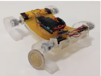
The main contribution of this work is the novel, miniature, untethered, and legged, soft robot design called the SQuad, shown in Fig. 1. As another major contribution, we fabricated a rigid PLA (Polylactic Acid) twin and two more hybrid versions in order to study the effects of body and leg compliance on 2377-3766 © 2020 IEEE. Personal use is permitted, but republication/redistribution requires IEEE permission.
Fig. 1. The SQuad with PDMS body and PDMS c-shaped legs.
the miniature mobile robot locomotion. The soft and hard legs were switched between the soft body and hard body to create hybrid robots to inspect the effect of the body and leg compliance individually. Using the four robots, we performed walking and obstacle climbing experiments. Our results indicate that, thanks to the body undulations and shock absorption properties of the soft robot; better walking and obstacle clearance characteristics can be achieved. Additionally, the body compliance seems to play a more important role in scaling obstacles compared to the leg compliance. Pitch and roll angles and centroid positions of the robots were measured and compared using the OptiTrack Motion Capture System. To the best of our knowledge, there are no other works in the miniature and soft robotics literature that studies the disparities between soft and hard bodies with soft and hard legs and inspects their effects individually in terms of obstacle climbing capabilities and locomotion characteristics.
II. DESIGN
SQuad has four c-shaped legs made out of Polydimethyl-siloxane (PDMS) legs. Each of the legs are driven individually by a miniature DC motor. The legs’ speeds and positions are controlled using miniature absolute position sensors. The robot carries a printed circuit board (PCB) made out of flexible poly-imide sheets, which is used to run and control the motors. A single cell Lithium-Polymer battery is used to power the robot. The assembled robot fits into a box of 15 cm x 10 cm x 4 cm and weighs 69 grams.
A. C-Shaped Leg Design
In order to utilize the softness of the robot to the maximum possible extent, a simple leg design is chosen. A simple leg design would allow the body to adapt to the surface condi-tions without requiring much control effort. Among potential candidates, c-shaped legs, first introduced in Rhex [17], were chosen because of their impressive obstacle scaling capabilities. It is also a design, whose stiffness can easily be manipulated using different materials, and it can be manufactured easily. Its
Fig. 2. Stress analysis of a c-shaped leg.
rounded shape provides the distribution of stresses upon impact. Last but not least, such a leg design has previously been shown to work on miniature legged robots [16], [18].
The reasons given above lead us to design and fabricate spe-cially designed c-shaped legs to be used for SQuad locomotion. In order to make the c-shaped legs strong enough to carry the robot’s weight; different thicknesses and radii were put to trial and a crude search on the c-shaped leg design space was carried out. The analysis tool of the Autodesk Fusion 360 CAD software was used in order to estimate the displacements and stresses. By improving and iterating the c-shaped leg design, the dimensions of the leg are determined in order to make four legs carry the robot (refer to Fig. 2). The Young’s Modulus of 5:1 ratio PDMS is found as 1.54 MPa using a tensile test machine; and the Young’s Modulus of the hard PLA leg is chosen as 3.5 GPa. The analyses distributed the weight of the body and external components such as the PCB and a battery to four legs in order to see if they would be able to carry the body. One single leg supports about 10.15 grams of mass and this corresponds to a displacement of 2.75 mm at the tip of the leg using the current design. Therefore the stiffness of the PDMS leg becomes 36.17 N/m. The stiffness of the hard PLA leg is calculated as well and it is found as 81.234 kN/m. The maximum length of the leg in x and y directions are 36 mm and 40 mm, respectively and the thickness is 10 mm. The weight of a single PDMS leg is 7 grams whereas a single 3D printed PLA leg with a thin layer of PDMS coating weighs 4.2 grams.
B. Body Design
The body’s middle section is not fully rigid; since PDMS is a relatively heavy material in comparison to other structural materials that are used in miniature robot fabrication. A design resembling the ‘union jack’ is used in order to reduce the weight and retain the body’s original form as much as possible. The body has a length of 100 mm and a width of 55 mm. The soft body weighs 36.25 grams including the flexible PCB and without battery. Whereas the hard body weighs 34.13 grams including the standard PCB and without battery.
A stiffness study was done in order to demonstrate the flexibil-ity of the soft robot. The analysis tool of the Autodesk Fusion 360 CAD software was used to perform the analysis. The Young’s Modulus of 10:1 ratio PDMS is found as 1.37 MPa using a
Fig. 3. CAD drawings of parts in the leg assembly. (a) Motor connector assembly, (b) soft leg with motor connector, rotary sensor and motor.
tensile test machine; and the Young’s Modulus of the hard PLA body is chosen as 3.5 GPa. The X axis is along the length of the body and the Y axis is along the width of the body. The stiffness around the Y axis was found to be 0.4316 N/m for the soft body and 1047.12 N/m for the hard body. The stiffness around the X axis was found to be 4.62 N/m for the soft body and 10.6 kN/m for the hard body. This preliminary analysis shows the drastic yet expected difference between the two robots.
C. Motor Connector Design
Small DC motors were used as actuators in SQuad (and in the other test robots). The hard body robots use 136:1 gear ratio Pololu motors whereas the soft body robots use 700:1 gear ratio Pololu motors since the soft body robots require slightly higher torque during operation due to larger surface contact caused by the body undulations, resulting with higher friction. The motors are connected to the c-shaped legs via 3D printed PLA connectors. Between the motors and the legs, there are infinite turn potentiometers used as absolute encoders that can provide phase information in order to establish control of speed and position of the legs.
Connecting the designed soft legs to the motors proved to be a challenge due to the differences between the motor and the sensor dimensions. The rotary encoders have an opening which is D-shaped with approximate shaft radius of 5 mm. On the other hand, the Pololu gear motors used in our robot only have a shaft diameter of 2 mm. A connection part, which would be linked to both of these parts and the leg, was designed and fabricated.
During initial tests, it was experienced that when the motor connection part is rigidly embedded to the leg and when this single part is glued to the motor shaft, it makes it impossible to replace the leg in case of a motor or a sensor failure without damaging it. Hence, a two piece motor connector was designed of which the first part is glued to the motor shaft and then the leg is screwed via a set screw to the second part. This enables us to replace any component in the leg assembly if there is any failure. It also enables us to test different types of legs on a body without replacing the motors, which are the most expensive components of our robot. The motor connector design is shown in Fig. 3(a). The connector assembly is 3D printed using PLA. The gray part is encapsulated inside the PDMS leg during molding and it has an M3 thread for the set screw. It also has pores in x, y and z
direction so that it does not move inside the leg. The red part in Fig. 3(b) can be detached after the mold is cured and later it is glued to the motor shaft.
D. PCB Design
In order to both reduce the weight and have flexibility; a PCB solution that uses polyimide sheets laminated outside with a copper layer were selected.
In the middle of the circuit board, an ArduinoTMPro Micro was stationed. Two L293DD H-Bridge motor drivers complete the main components on the circuit board. Furthermore, capac-itors were placed at the motor connections in order to prevent any instantaneous voltage fluctuations. Several other capacitors were included in the circuit to be used as filters. Also, a switch and a 3.7 V–5 V step-up regulator were included.
The designed board was ordered through a mass manufacturer. The board was made from a double-sided copper-clad polyimide film, making the PCB flexible. Pre-drilled vias and pads ensured an easy assembly and soldering of the circuit components. The flexible PCB is used for the soft body whereas for the hard body same design was ordered as a standard FR4 PCB to reduce cost. The flexible boards are shown in Fig. 4.
III. FABRICATION
A. Body Fabrication
PDMS Sylgard 184 was mixed in a 10:1 ratio of a pre-polymer and cross-linker and mixed very well. After mixing, a vacuum oven was used for the elimination of the air bubbles. PLA mold was covered with a layer of Ease Release 205 (Smooth-On) then, using a syringe, PDMS was poured into the mold and placed in the oven at 70◦C for 4 hours (Fig. 5(a)). In order to fully complete the curing process, the mold was taken out from the oven and kept at room temperature for 18 hours.
B. C-Shaped Leg Fabrication
C shaped leg fabrication follows the same steps as the body fabrication. Since the legs made of 10:1 ratio PDMS cannot support the body weight, 5:1 ratio PDMS was used which added extra stiffness to the leg structure. Also, 5:1 ratio PDMS requires only 1 hour at 70◦C in the oven to cure, unlike the 10:1 ratio PMDS which requires 4 hours. The 3D printed motor connectors were placed into the grooves specified for them; in order to get them embedded inside the legs, as can be seen in Fig. 5(c).
Fig. 5. Fabrication process of the soft body and the soft leg. (a) 3D-printed body mold, (b) PDMS soft body, (c) 3D-printed leg mold, (d) PDMS soft leg.
IV. CONTROLLERDESIGN
The controller is based on a classical model of a DC motor which includes a voltage source, a resistance and back emf induced by the DC motor [19]. The inductance is not taken into account for convenience since we do not measure or control the current input to the system and the value of inductance is small enough to neglect for the utilized motors. The states of the DC motor and leg system consists of the rotation angle of the motor
(θ) and the rotational rate of the motor ( ˙θ). The control system is
a full state feedback control system, which is based on a Linear Quadratic Regulator (LQR). In order to have a full state feedback control, all of the states should be measured, whereas our system is only able to read the position information of the motor using the rotary position encoders. The rotational rate( ˙θ) could not be measured directly using the rotary position encoders, therefore it needs to be estimated using an observer, ideally a Kalman filter. Hence, a Linear Quadratic Estimator (LQE) was used as an observer to obtain a full state feedback controller. By using LQR along with the LQE, we have obtained a Linear Quadratic Gaussian Controller (LQG) to control the gait of the robot. Using the LQG, the gait of the robot is set to a trot gait, where the two diagonal leg pairs are half a period apart in phase from each other, but running at the same frequency.
V. EXPERIMENTALRESULTS ANDDISCUSSION
In order to test and compare the capabilities of SQuad, its hard twin and two other configurations (a robot with a hard body and soft legs, and a robot with a soft body and hard legs) were built and a set of experiments were conducted. The soft body is only about 2.1 grams heavier than its hard twin body which is negligible considering the total weight of SQuad (69 grams). However, a single soft leg is about 2.8 grams heavier than its 3D
Fig. 6. Walking pictures of 4 different robot configurations. (a) SQuad, (b) soft body - hard leg, (c) hard body - hard leg, (d) hard body - soft leg.
TABLE I
TRANSLATIONALSPEEDS FORDIFFERENTCONFIGURATIONS
printed twin. This makes SQuad about 13 grams heavier than its fully hard twin robot. The speeds of the motors are kept the same between the robots at 0.5 Hz stepping frequency and trot gait is used for all experiments. The hard PLA legs were coated with a thin layer of PDMS to eliminate the differences that would be caused by the material friction properties.
The walking speed, pitch and roll angle and centroid height was measured using the OptiTrack Motion Capture System at 120 Hz sampling rate. Finally, obstacle climbing performances of the robots were measured.
A. Speed Analysis
The walking characteristics of the robots are studied first. The first data presented is the speed data for all the robots. A screen shot from the walking experiments is presented in Fig. 6.
The speed data is given in Table I and it reveals the advantage that the soft legs provide when it comes to traction. For both soft body and hard body, the soft legs are slightly faster than the hard legs. This is mainly due to the fact that soft legs conform better to the ground, increasing the surface area that is in contact with the ground, hence increasing the friction force. Regardless of the leg type, soft body performs a slower walking motion than the hard body. This is rather expected since some of the input energy is consumed on robot’s undulation rather than its locomotion.
B. Pitch and Roll Angle Analysis
Pitch and roll angle analysis is crucial to determine the smoothness of the walking. Three markers were placed on both
Fig. 7. Pitch angle data of soft and hard bodies. (a) Soft body configurations, (b) hard body configurations.
the soft and the hard bodies to track the motion of the robots. For the hard body, the motion tracking was straightforward since the relative positions of the markers did not change and the software could easily output the roll-pitch-yaw and position data. However for the soft body, post processing was required. The position data from the markers on the soft body was obtained individually and later, the pitch and roll angles were calculated by creating vectors between the markers and using rotation matrices.
It is hard to define the pitch angle for a soft robot since it has a different value on every individual position on the body. However for convenience, we have defined the pitch angle of our soft robot as the angle between the front tip and the rear tip of the soft body. Similarly for the roll data, the front and rear tip was used.
According to the data presented in Fig. 7 the pitch angle for the soft bodied robots remain between ±10◦ making the translational motion smoother than the hard bodied robots. The soft leg results in higher pitch angle in the positive range and lower in the negative range for the soft bodied robots however the difference is not considerable. The impact forces at the moment where a leg touches the ground are more visible for the hard legged soft bodied robot.
For the hard bodied robot the pitch is mainly between 0◦and 20◦. The pitch up behavior is caused by the moment balance of the robot during forward locomotion and for the hard leg
Fig. 8. Roll angle data of soft and hard bodies. (a) Soft body configurations, (b) hard body configurations.
the pitch tends to go higher. We observed that the rear legs slip during the pitch up phase causing the front of the robot to rise more.
A single cycle of pitch up and pitch down phase takes about 1 second for the hard bodied robots whereas it takes about 2 seconds for the soft bodied robots. This is due to the hard robots‘ inability to pitch down, whereas the soft robots’ pitch angles can get negative. It can also be observed that the pitch angle waveform of the soft robot would become similar to the hard robots‘ pitch angle if the absolute value of the soft robots’ pitch angle were used. On the other hand, the ability of the soft bodied robots to pitch up and down makes the walking behavior smoother.
The pitch angle depends heavily on the stiffness of the body whereas the roll angle depends more on the stiffness of the legs. From Fig. 8 we see only small difference between the four different robot configurations for the roll angle, mainly due to the fact that the soft legs are much stiffer than the soft body. Even though the hard legs are also much stiffer than the soft legs, the small amount of force applied to them makes this difference not as significant as in the case of the soft body.
The roll data also includes information about how the soft body is better at dampening the impact forces during locomotion. When the roll angle switches from positive to negative and vice versa in Fig. 8(b), the data clearly shows small peaks which indicate the impacts of the legs with the ground. For
hard robot also is not constant due to the leg rotations. Therefore it is extremely difficult to track the center of gravity of the robots precisely. However, in order to get a sense of how smooth the locomotion is; a position analysis was done for the center of geometry, or centroid of the bodies.
It is straightforward to calculate the centroid position of the hard body using the position data obtained by the motion capture system. For the soft body, we tried to place a marker right at the centroid but the motion capture system could not track it accurately especially when the body buckled inwards. Therefore the centroid position was assumed as the center between the front tip and rear tip of the body. Even though it is not exactly the centroid for the soft body, we observed that this is a fair assumption after comparing the data with the experiment videos. When the hard robot is stationary with its body parallel to the ground and when the legs are adjusted to result in maximum height; centroid height is approximately 36 mm. For the soft robot, this value drops a couple of millimeters since it tends to bend downwards under the load of its own weight.
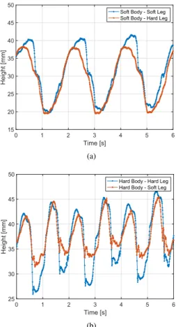
From the data presented in Fig. 9 it can be seen that the centroid of the soft body generally tends to be below 36 mm and it drops down to 20 mm at its minimum.
For the hard body; the soft legged hybrid has the same high peaks as the hard legged robot. However the lowest peaks of soft legged hybrid are considerably higher than the hard legged robot. This behavior is observed visually as well and the reason is that when the hard body drops from maximum pitch to minimum pitch, hard leg slips during initial impact; whereas the soft leg grips to the point of first contact, causing the centroid to remain higher.
Generally a low centroid position is preferred for better obsta-cle climbing performance since it reduces the chance of flipping during climbing. Hence, the soft body should have an advantage since the centroid drops to lower heights than the hard body and this was observed in the experiments.
The centroid position analysis reveal how drastic the robot’s dynamics change due to the body compliance. Even though the hard and soft bodies take steps with the same frequency, the oscillations in the centroid positions are slower in the soft body compared to the hard body. Ideally, the stepping frequency should be selected by considering the body dynamics with the resonant frequency of the system in mind. However, we do not currently have a model representing the dynamics of such a soft-bodied mobile robot. In this study, the stepping frequency was selected by considering the limitations of the motors rather then the dynamics of the system.
D. Obstacle Climbing Analysis
Evaluating and comparing the performance of the robots by testing their ability to climb obstacles is a common method. For
Fig. 9. Centroid height data of soft and hard bodies. (a) Soft body configura-tions, (b) hard body configurations.
TABLE II
MAXIMUMOBSTACLESSCALED FORDIFFERENTCONFIGURATIONS
the obstacle climbing tests, the obstacle height was gradually increased and the maximum heights that the robots can scale was recorded.
The maximum obstacle height that the robots could climb were presented in terms of body heights in Table II. The body height is chosen as the neutral height when the roll and pitch angle is zero and the legs are positioned so that the robots are at their maximum heights which is 36 mm.
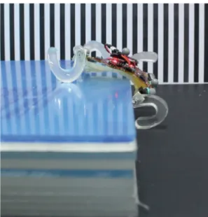
As expected, the soft bodied and soft legged robot (SQuad) performed the best with a scalable obstacle height of 51.8 mm (1.44 Body Heights) whereas the fully hard test robot performed the worst at 31.7 mm (0.88 Body Heights).
The effect of the body type is significant for the obstacle climbing tests. Regardless of the leg type, the soft bodied robots were able to climb higher obstacles than the hard bodied robots could. Similarly, regardless of the body type, both the soft body and hard body performs better with a soft leg rather than a hard leg.
Fig. 10. SQuad climbing the obstacle 1.44 times its body height.
A screen shot of SQuad climbing the obstacle 1.44 times its body height is shown in Fig. 10.
VI. CONCLUSION ANDFUTUREWORKS
In this work, a new untethered miniature soft quadruped, SQuad is presented and its performance is compared with a fully hard test robot and two hybrid test robots. SQuad has four c-shaped legs, all driven individually by a DC motor. The body of the robot and its legs are made out of PDMS and it carries a PCB made out of flexible copper-clad polyimide sheets. The c-leg design proved out to be crucial for the robot to show very strong obstacle scaling capabilities. The walking and obstacle clearance experiments showed how the soft robot was better in comparison to its rigid twin and the hybrids; with less tremble in pitch angle and centroid displacement. Stiffness analyses also showed the major flexibility difference between the robots; and ultimately, how it helped the soft robot achieve the tasks better.
As the future works, we will model the robot in order to opti-mize body and leg designs; add a communication method such as Wi-Fi or Bluetooth to the microcontroller in order to control the robot with external and real-time inputs; try out different gaits to compare different maneuverability characteristics and obstacle climbing performance; design and build a contraction mechanism for the body and the legs in order to further utilize the softness of the robot and to pass through openings smaller than its cross-section area.
[2] K. C. Galloway et al., “Soft robotic grippers for biological sampling on deep reefs,” Soft Robot., vol. 3, no. 1, pp. 23–33, 2016.
[3] X. Huang, K. Kumar, M. Khalid Jawed, Z. Ye, and C. Majidi, “Soft electrically actuated quadruped (seaq) integrating a flex circuit board and elastomeric limbs for versatile mobility,” IEEE Robot. Autom. Lett., vol. 4, no. 3, pp. 2415–2422, Jul. 2019.
[4] C. Laschi, M. Cianchetti, B. Mazzolai, L. Margheri, M. Follador, and P. Dario, “Soft robot arm inspired by the octopus,” Adv. Robot., vol. 26, no. 7, pp. 709–727, 2012.
[5] H.-T. Lin, G. G. Leisk, and B. Trimmer, “Goqbot: A caterpillar-inspired soft-bodied rolling robot,” Bioinspiration Biomimetics, vol. 6, no. 2, 2011, Art. no. 026007.
[6] T. Umedachi and B. A. Trimmer, “Design of a 3D-printed soft robot with posture and steering control,” in Proc. IEEE Int. Conf. Robot. Autom., 2014, pp. 2874–2879.
[7] A. Menciassi, S. Gorini, G. Pernorio, L. Weiting, F. Valvo, and P. Dario, “Design, fabrication and performances of a biomimetic robotic earthworm,” in Proc. IEEE Int. Conf. Robot. Biomimetic, 2004, pp. 274–278.
[8] Y. Sugiyama and S. Hirai, “Crawling and jumping of deformable soft robot,” in Proc. IEEE/RSJ Int. Conf. Intell. Robots Syst., 2004, vol. 4, pp. 3276–3281.
[9] M. T. Tolley et al., “A resilient, untethered soft robot,” Soft Robot., vol. 1, no. 3, pp. 213–223, 2014.
[10] C. D. Onal and D. Rus, “Autonomous undulatory serpentine locomotion utilizing body dynamics of a fluidic soft robot,” Bioinspiration
Biomimet-ics, vol. 8, no. 2, 2013, Art. no. 026003.
[11] Y. S. Song et al., “Soft robot for gait rehabilitation of spinalized rodents,” in Proc. IEEE/RSJ Int. Conf. Intell. Robots Syst., 2013, pp. 971–976. [12] N. W. Bartlett et al., “A 3D-printed, functionally graded soft robot
powered by combustion,” Science, vol. 349, no. 6244, pp. 161–165, 2015.
[13] J. T. Muth et al., “Embedded 3D printing of strain sensors within highly stretchable elastomers,” Adv. Mater., vol. 26, no. 36, pp. 6307–6312, 2014.
[14] Y. Mengüç et al., “Wearable soft sensing suit for human gait measurement,”
Int. J. Robot. Res., vol. 33, no. 14, pp. 1748–1764, 2014.
[15] M. Wehner et al., “An integrated design and fabrication strategy for entirely soft, autonomous robots,” Nature, vol. 536, no. 7617, pp. 451–455, 2016.
[16] A. F. Guc, M. A. I. Kalin, C. Karakadioglu, and O. Ozcan, “C-quad: A miniature, foldable quadruped with c-shaped compliant legs,” in Proc.
IEEE Int. Conf. Robot. Biomimetics, Dec. 2017, pp. 26–31.
[17] U. Saranli, M. Buehler, and D. E. Koditschek, “RHex: A simple and highly mobile hexapod robot,” Int. J. Robot. Res., vol. 20, no. 7, pp. 616–631, 2001.
[18] R. S. Pierre and S. Bergbreiter, “Gait exploration of sub-2 g robots using magnetic actuation,” IEEE Robot. Autom. Lett., vol. 2, no. 1, pp. 34–40, Jan. 2017.
[19] G. F. Franklin, J. D. Powell, and A. Emami-Naeini, Feedback Control of