JABFM
Journal of Applied Biomaterials & Functional Materialshttps://doi.org/10.1177/2280800019882645
Journal of Applied Biomaterials & Functional Materials
October-December: 1 –11 © The Author(s) 2019 Article reuse guidelines: sagepub.com/journals-permissions DOI: 10.1177/2280800019882645 journals.sagepub.com/home/jbf
Creative Commons Non Commercial CC BY-NC: This article is distributed under the terms of the Creative Commons Attribution-NonCommercial 4.0 License (http://www.creativecommons.org/licenses/by-nc/4.0/) which permits non-commercial use, reproduction and distribution of the work without further permission provided the original work is attributed as specified on the SAGE and Open Access pages (https://us.sagepub.com/en-us/nam/open-access-at-sage).
Introduction
Poor retention and instability of dentures are the chief rea-sons for functional problems and complaints in edentulous patients. Bone resorption is often remarkably greater in the mandible than in the maxilla in these patients.1 Due to this
natural process in the mandible, there is a need to increase retention and support of overdenture prostheses in con-junction with implant rehabilitation.2 Since several studies
reported3,4 high success rates for implant rehabilitation,
overdentures have become an acceptable alternative for patients with severe residual ridge resorption. In addition
Effect of mucosa thicknesses on stress
distribution of implant-supported
overdentures under unilateral loading:
Photoelastic analysis
Ozgun Yusuf Ozyilmaz
1, Filiz Aykent
2and Gulsum Sayin Ozel
3Abstract
Introduction: The aim of this study was to evaluate the effect of different heights of attachment and mucosa thicknesses
on the stress distribution of two implant-retained mandibular overdenture designs under loading using the photoelastic stress analysis method.
Materials and methods: Six photoelastic models of an edentulous mandibula were fabricated with two solitary
implants that were placed in the canine regions. The attachment systems studied were ball and locator stud attachments. Both the ball and locator groups included three models that had different residual ridge heights so as to provide different mucosa thicknesses (1 mm–1 mm, 1 mm–2 mm, 1 mm–4 mm). A static vertical force of 135 N was applied unilaterally (each on the right then the left side) to the central fossa of the first molars. Models were positioned in the field of a circular polariscope to observe the distribution of isochromatic fringes around the implants and the interimplant areas under loading. The photoelastic stress fringes were monitored and recorded photographically.
Results: The ball attachment groups showed higher stress values than did the locator groups under loading. Both
attachment systems produced the lowest stress values in stimulated 1 mm–1 mm mucosa thickness models. The models with 1 mm–2 mm mucosa thicknesses showed higher stress values than did other models for both attachment systems. The highest stress value observed around both attachment systems was the moderate level in all test models.
Conclusion: In different height mucosa thicknesses, locator attachment models distributed the load to the other side
of the implant and its surrounding tissue, whereas the ball attachment did not. Regardless of mucosal thickness and attachment type, the implant on the loading side was subjected to the highest stress concentration.
Keywords
Solitary implants, photoelastic analysis, mucosa thickness, abutment height, stress distribution Date received: 14 May 2019; revised: 18 September 2019; accepted: 23 September 2019
1Department of Prosthodontics, Faculty of Dentistry, Bezmialem Vakif
University, Istanbul, Turkey
2Department of Prosthodontics, Faculty of Dentistry, Yildirim Beyazit
University, Ankara, Turkey
3Department of Prosthodontics, Faculty of Dentistry, Istanbul Medipol
University, Istanbul, Turkey
Corresponding author:
Dr Ozgun Yusuf Ozyilmaz, Department of Prosthodontics, Bezmialem Vakif University Faculty of Dentistry, Vatan Road, Istanbul, 34214, Turkey.
Email: [email protected] Original Research Article
to the increased retention and stability that an implant-supported overdenture (ISOD) allows, further advantages over conventional complete dentures include increased comfort and chewing abilities,1,5 protection of the residual
ridge, and an enhanced quality of life.6
According to the McGill Consensus Statement of 2002, the primary treatment option for edentulous patients is ISOD using two solitary implants in the mandible.2,3
Mandible overdentures planned with two implants satisfy the requirements for treatment and lead to low surgical damage of tissue; this method also costs less and is the simplest proper prosthodontic procedure.7 The abutment
types commonly used for the two implant-supported man-dible overdentures include bars of different designs as well as balls and magnets.8-11 The recently presented locator
system has been widely used by dentists and has gained a considerable market share in the implant industry.8 It has
been introduced as an alternative single attachment against the most used retention system, which is called the ball anchor system. Although both stud attachment systems have been used for several years in the implant industry, there remains a lack of detailed information about them. There are various opinions regarding the superiority of each, the various implant heights, and mucosa thickness on the stress distribution.12,13
The soft tissue structure and shape around the bone and the implant types used might affect the stress distribution in the cortical bone that is located in the peri-implant zone. Overloading situations may also cause wearing out of parts of the implant system or micro/macrofracture of the implant due to the incompatibility between components or failure of the implant due to crestal bone loss.8,14 Height of
the attachment and mucosa thickness are also important factors in the design of ISODs. To reduce the lever arm effect that increases the level of stress transmitted to the peri-implant bone, the attachment must be as short as pos-sible. The height of the attachment also influences space requirements inside the denture, and fractures may occur with insufficient acrylic resin thickness.15,16 Mandible
bone resorption can occur at various levels in the right and left side of the anterior mandible.17 This condition
intro-duces the need to use an attachment with a different
vertical height level, such that two independent implants can be positioned at the same occlusal height, parallel to the occlusal plane. If one implant was higher than the other, the prostheses would disengage from the lower implant during function and would rotate primarily on the higher implant. This situation accelerates the wear of the attachment on the lower implant, and because the higher implant receives the majority of the occlusal load, an increased amount of crestal bone loss can occur.18,19
Similarly to other bones, mandibular bone can be regarded as a composite material.20 Polymers and
fiber-reinforced polymers can be used to replicate the mandible spongy and cortical bones, respectively.21 The mandible
model used within this investigation is a photoelastic poly-mer based on an epoxy resin.22 It has an elastic modulus of
about 2 GPa,23 thus the elastic properties of our model is in
between the moduli of spongy and cortical bone.24
A variety of techniques are used to simulate the mathe-matical and visual evaluation of the stress distribution of the implant and bone during chewing in the mouth. These are photoelastic stress analysis (PESA), two-dimensional (2D) or three-dimensional (3D) finite element analysis (FEA), and strain-gauge (SG) analysis.25 Experimental SG
analysis on mandible models is essential to calibrate theo-retical FEA mandible models.26 Among these methods,
PESA eliminates the variations caused by the patient or the operator performing the experiment. This technique has been extensively used to investigate the interaction of tis-sue response and stress distribution among implant–bone prosthetic restorations and physical properties of implants in dentistry.27-29 Several studies have evaluated stress
dis-tribution between the same heights of attachments using FEA1,5 and SG;30 the effects of implant angulation and
prostheses connection have also been investigated,31 but
there is no study that evaluates different heights of attach-ments by using PESA. Therefore, the aim of this in vitro study was to evaluate the influence of different heights of attachments and mucosa thickness for two different ISODs, namely, the ball and locator attachment (Figure 1), on the vertical pressure and stresses around the implant surface bone under unilateral loading on overdenture pros-theses using PESA method.
Materials and methods
Preparation of acrylic and photoelastic models
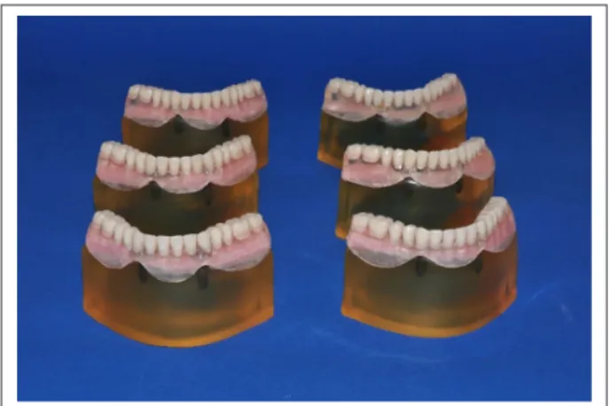
An edentulous mandible wax model (Poliwax, Bilkim Kimya, Izmir, Turkey) was fabricated and shaped in the same vertical height level for both sides of the mandible. A wax model was obtained from a patient who had adequate bone height of the mandible. This model was duplicated twice, and the midline of the second wax model was marked with a digital caliper. The left mandible area was diminished 1 mm below the right side (1 mm–2 mm). The third wax model was also shaped as the left side of the jaw was 3 mm lower than the right side (1 mm–4 mm). Then, three master wax models (1 mm–1 mm, 1 mm–2 mm, 1 mm–4 mm) were obtained and duplicated; the six models were obtained to produce two of each of the master mod-els. These wax models were turned into six edentulous mandible acrylic models (Meliodent; Heraeus Kulzer, Hanau, Germany, Figure 2).
The acrylic models were polished with 320-, 400-, or 600-grid silicon carbide abrasive paper. Two perforations were made in the canine areas with a parallelogram (Orthofex, Fogászat Gyártơ, KFT, Budapest, Hungary) and a distance of 22 mm between each of the two canine teeth was set in a similar manner to that in the mouth.27,32
Screw-type implants (Fixture OsseoSpeed™ Implant, Astra Tech, Mölndal, Sweden), 4.0×11 mm, were placed into holes in the acrylic models. Stud attachments, namely, the ball and locator, were merged with implants on the models. Using a drill at the top of the parallelogram, the height difference between implant levels was checked on both sides of the mandible to determine the reference point; ball attachment levels were checked from there at the peak point, while locators were controlled from their buccal points. Precise adjustments were made by checking the lines indicating the change in mm of the up-and-down movement on the side of the parallelogram to determine whether the vertical heights were the same. Thus, the
implants were positioned evenly on top of the alveolar ridge. Six silicone impressions (Zetaplus, Zhermack, Rovigo, Italy) were derived from acrylic models that have implants and then photoelastic resin material (PL–2 and PLH–2; Vishay Measurements Group, North Carolina, USA) based on an epoxy resin was poured into the silicone molds according to the manufacturer’s recommendations.
Creation of mucosa morphology
As the prosthetic ending process on the model can create stress, the negatives of models were obtained with silicone impressions and stone models were prepared. Models were measured with a digital caliper from the center of the stone mold to the middle of the implants, and the same measured distance was marked on the distal side of the implants as a horizontal projection. These areas were defined as the lim-its for the determination of different mucosa heights while arranging the process of mucosa heights. Posterior edentu-lous areas of photoelastic models were fixed by light-polymerized base plates (Vertex U.V. Light Curing Trayplast, Vertex Dental, Zeist, Netherlands) at a 3 mm thickness to represent soft tissue thickness.33,34
Mucosa around the implant of the two models of 1 mm– 2 mm were prepared as 2 mm around the implant on the left side and 1 mm around the implant on the right side, while mucosa around implant circles of the 1 mm–1 mm models were prepared with a base plate with a thickness of 1 mm. In the two remaining models, to simulate mucosa thickness a 4-mm base plate was used in the left side of the implant and was set in 1-mm base plates in the right side of the implant. However, the base plate thickness was 2 mm (Figure 3), and 1 mm thickness was needed. The base plate was then thinned homogeneously on the glass plate with the help of a glass cup until it reached 1 mm.
Standardization of dentition and prosthetics
finishing procedures
Pink modeling wax was placed on the mandible model with the mucosa height base plate set and the artificial teeth were set up (Figure 4). Then, a silicon mold was made from this denture to standardize the tooth arrange-ment for all models. After the wax was removed with hot water, the mold in which the teeth were placed for a trans-parent acrylic (Orthoplast, Vertex Dental, Zeist, Netherlands) was polymerized by heat. The mucosa-formed gypsum model was placed into a silicon mold with hand pressure, and the overflows were removed and placed in a Biodent oven (Dikan 105, Mersin, Turkey) for 10 min-utes at 2.5 bar at 55°C to polymerize the transparent acrylic. By using a transparent material in the construction of the prostheses, it was hoped that light would pass through the model in order to observe the stress lines.27,33
Ball and locator abutments were mounted on the models
Figure 2. Acrylic models prepared according to different
mucosa heights and then be converted to photoelastic models by placing ball and locator attachments (1 mm–1 mm; 1 mm–2 mm; 1 mm–4 mm).
using a torque switch with a force of 25 Ncm (Astra Tech, Mölndal, Sweden). While the process kits were put on the locator abutments, titanium thread pieces were put on the ball abutments. Overdenture prostheses were fitted to the photoelastic models by adding transparent acrylic to the inner surfaces of the prostheses to accommodate the female parts.35 They were then placed in the Biodent oven
again for polymerization. To simulate the mucosa in the photoelastic model, a fluid-like elastic material (Gingifast; Zhermack SpA, Badia Polesine, Italy) was inserted into the gap created by the light-polymerized base plate on the inner surfaces of the prostheses, and prostheses were shaped to clearly view the stress lines around the implants during the photographing of the photoelastic models (Figure 5).
Mounting of models in the polariscope device
and loading
Before application of loading, all photoelastic models were checked by photograph using a circular polariscope to ensure that any stress-fringe was or was not in the models.36
Mineral oil (Castrol, Istanbul, Turkey) was varnished on all models in order to facilitate photoelastic observation dur-ing evaluation. The loaddur-ing process was carried out on a universal test machine (TSTM 02500, Elista Ltd., Istanbul, Turkey). A total of 135 N force was applied to the central fossa of both first molar teeth in the vertical direction.27,32
This load amount was chosen since it is close to the highest bite force measured in patients who use ISODs.37 This
loading region was chosen because it is located in the zone where chewing strength is highest in patients using ISODs, as the most effective elevator muscles are in this zone.27,32
The results of stress tests of the models were observed by a digital camera that was equipped with a macro lens (Macro Lens-Canon EF 100 mm F/2.8, Canon Inc. Headquarters, Tokyo, Japan) to obtain clear images (Canon EOS 650D, Canon Inc. Headquarters, Tokyo, Japan). A ring flash (Sigma EM 140 DG; Sigma Corporation, New York, USA) was used to prevent the beam from shading the image, and to ensure that the illumination of the photo-graphed pattern was identical in each region. Models were kept at 50°C for 20 min in an oven to eliminate residual
Figure 3. (A) Frontal and (B) Occlusal view of different mucosa heights during preparation by light-polymerized base plates which
created gap for fluid-like elastic material for inner surfaces of the prostheses.
Figure 4. Standardized artificial teeth arrangement to use in
all models. The impression was taken by this master model so that obtained guidance teeth model transferred to all other models from this master model to ensure standardization of all models.
Figure 5. Appearance of finished prostheses with mimic
mucosa before occlusal loading on photoelastic models. Prostheses were shaped to clearly view the stress lines around the implants during the photographing of the photoelastic models.
stress in the photoelastic models after each loading.34
Before each installation, the models were examined in the polariscope device to make sure there were no stress accu-mulation lines. The stress concentrations and their sites were subjectively compared by the same evaluator. The fol-lowing terminology was used to interpret stress intensity (number of fringes) in the polariscope under white light:28
1. Low stress – 1 or 0 fringes, 2. Moderate stress – 2 or 3 fringes, 3. High stress – more than 3 fringes.
Results
Similar stress fringes were observed in terms of attach-ment types with the same alveolar bone level in each implant side; therefore, only the results from the right side are presented. However, both attachments’ patterns and implants with the different alveolar bone levels are pre-sented from both right and left-side loading. Before occlusal loading, each model was examined to ensure that there was no residual stress.
Right-side loadings
Ball attachment 1 mm–1 mm abutment height model. Sym-metrically moderate stress values were observed in the api-cal region of the implant on the force-applied side. The mesial coronal region of the implant had a moderate stress spread over a large area. Moderate stress was observed in the mesial apical region of the contralateral implant. Mid-span moderate stress was observed in the coronal distal region (Figure 6(a)).
Ball attachment 1 mm–2 mm abutment height model. At the right apical side of the implant, the mesial and distal
regions were found to have moderate stresses, while the collar region had low stress. Low stress was observed dis-tal to the apical side of the contralateral implant, and low stress was also found in the mesial aspect (Figure 6(b)). Ball attachment 1 mm–4 mm abutment height model. In the apical region of the implant on the loading side, a moder-ate stress was observed symmetrically. Stress in the apical region spread widely from the distal side of loading implant to the alveolar crest. Low stress was observed in a very narrow area of the mesial apical of the contralateral implant (Figure 6(c)).
Locator attachment 1 mm–1 mm abutment height model. Moderate stress fringes were observed at the apical side of the loading side implant and at the mesial apical triplet, and low stress was observed in the distal coronal region. Moderate stress was observed along the mesial axis of the contralateral implant and at the distal apical area. In the apical region, a narrow field of moderate stress was observed (Figure 7(a)).
Locator attachment 1 mm–2 mm abutment height model. Moderate stress was observed on the apical right side of the implant. In the distal middle triple zone mod-erate stress was observed, and modmod-erate stress was also observed in the coronal region. Moderate stress was observed in the alveolar crest region between the two implants near the alveolar crest. Stress was observed moderately on the contralateral mesial apical triplet (Figure 7(b)).
Locator attachment 1 mm–4 mm abutment height model. Stress was observed moderately on the apical side of the implant on the loaded side. In the mesial apical tri-ple, there was a moderate stress. Moderate stress was also
Figure 6. (A) Stress patterns of ball attachment 1–1 mm loading from right side. (B) Stress patterns of ball attachment 1–2 mm
loading from right side. (C) Stress patterns of ball attachment 1–4 mm loading from right side. (D) Stress patterns of ball attachment 1–2 mm loading from left side. (E) Stress patterns of ball attachment 1–4 mm loading from left side.
observed in the apical of the opposite side of the implant. No stress was observed in the coronal regions between implants (Figure 7(c)).
Left-side loadings
Ball attachment 1 mm–2 mm abutment height model. Mod-erate stress value was observed at the apical side of the implant on the loading side. In the distal coronal region, moderate stress was observed. A moderate stress distribu-tion was observed over a wide area between coronal regions of the implants. At the apical side of the contralat-eral implant, moderate stress was observed (Figure 6(d)). Ball attachment 1 mm–4 mm abutment height model. At the apical left side of the implant, moderate stress was observed. Stress was observed in the middle apical triple region and moderate stress was seen in the distal apical triple and coronary when stress was detected (Figure 6(e)). Locator attachment 1 mm–2 mm abutment height model. At the apical and coronal side of the implant on the side of loading, moderate stresses were observed. In the alveolar crest region between the two implants, medium stress was found spreading over a large area near the crest. Stress was observed moderately at the apical side of the contralateral implant (Figure 7(d)).
Locator attachment 1 mm–4 mm abutment height model. Moderate stress was observed around the implant on the side of the loading. At the apical side of the con-tralateral implant, a moderate stress event was observed (Figure 7(e)).
Discussion
In this study, the 1 mm–1 mm mucosa thickness models showed lower stress values than those obtained from
models with 1 mm–2 mm and 1 mm–4 mm mucosal thick-nesses. This difference was determined to be greater in the locator model than in the ball attachment model. As a fur-ther consequence of the study, in models with different mucosal thicknesses, more stress was observed around the implant which is on the force-loading side.
In the literature, stresses on implants in ISOD prosthe-ses are usually determined by PESA.27-29,32-35,38,39 The
pho-toelastic mandible model used in current study consisted of integration of the implants with the epoxy resin, which simulates the bone tissue and also impression material in the ISOD to represent the mucosa around the stud attachments.32,34
The absence of differences between cortical and tra-becular bone, despite the resin being used to produce pho-toelastic mandible models with a modulus of elasticity similar to bone tissue, might modify the magnitude of the stress concentrations. However, neither the location of stress concentrations nor the behavior would be changed substantially.32 Soft tissue elasticity differs depending on
the amount of soft tissue and individual bone. In the ISOD model, such variables remain the same and can be con-trolled.40 Thus, the analytical results help to make accurate
predictions about implants and surrounding bone tissue. In the present study, the resin was hardened in a silicone mold, as was done in other studies.27,34 The implants used
were placed in acrylic models and then photoelastic resin models were prepared. This method aimed to prevent the stresses that might occur during the preparation of the nest in the photoelastic models. In many previous stud-ies27-29,32-35,38,39,41 the mucosa around the implants located
in the anterior region was eliminated, and artificial mucosa material was placed only in the posterior region under the prosthesis. This study was designed to provide conditions closer to the oral environment by using artificial mucosa to mimic material around the anterior implants.
Tanino et al.42 investigated the load transfer of
stress-relieving materials placed on two implants independently
Figure 7. (A) Stress patterns of locator attachment 1–1 mm loading from right side. (B) Stress patterns of locator attachment
1–2 mm loading from right side. (C) Stress patterns of locator attachment 1–4 mm loading from right side. (D) Stress patterns of locator attachment 1–2 mm loading from left side. (E) Stress patterns of locator attachment 1–4 mm loading from left side.
of each other using the FEA method. Again, Meijer et al.43
studied loading conditions on overdenture prostheses with two independent implants using the FEA method. In both studies it was noted that the largest stress values were seen around the implant on the loading side. Similarly, research-ers44 have examined the effects of different attachment
systems on the stress transmission of ISOD prostheses. In the distal region where force was applied, moderate stress development was observed, and very low stress occurred on the opposite side of where the force was applied. In this study, similar to the results of previous studies, the most intense stresses in unilateral loads were concentrated on the loaded side implant.
Both ball and locator systems used in the current study transmitted moderate stress to the implant–bone interface in all experimental models. This result is consistent with the study of da Silva et al.,45 who examined the stresses
that different retention types transmitted to alveolar bone and implants. The O-ring attachment system transmits stress to the implants at moderate levels. Machado et al.34
investigated the effects of the three different stud attach-ment systems on the stresses transmitted to the implants in implant-supported mandibular overdentures. Low levels of stress were found around the implants in the O-ring sys-tem. Fanuscu and Caputo44 reported that, in the two
differ-ent attachmdiffer-ent systems examined, the force was transmitted to the implants in the maxilla overdentures, indicating that the ball attachment system caused stress transmission on the loading side at a high level. The results of our study are in disagreement with these two studies. Differences in the magnitude of the stresses in available literature investiga-tions are thought to be dependent on the magnitude of force applied on models and the differences in the force application areas. It has been reported that the shift of the load site from anterior to posterior causes an increase in the stress of the toothless area and a decrease in stress in the implants.45,46
Ochiai et al.33 reported that in a PESA study, low stress
was observed in the loading side implant in the locator attachment system, while stress was distributed in the opposite side implants. Çelik and Uludağ27 observed a
higher stress level in the locator system than the ball sys-tem as a medium stress level. They again reported that the locator system distributed the stress in the opposite implant while the ball attachment system could not create it. The results obtained from this study support the results of stud-ies by Ochiai et al.33 and Çelik and Uludağ.27 In all locator
experiment models, the load was distributed on both implants, but more intense stress occurred in the loading-side implant. In ball attachment test models, lower stress intensity was observed in the 1 mm–2 mm and 1 mm–4 mm models on the opposite side of loading, regardless of loading site.
Hojo et al.47 examined locator and extracoronal
resil-ient attachment (ERA) attachment systems. They found
that the ERA system showed minimal differences in stress transmission between implants under unilateral loadings. The results from our study were similar to theirs, as we found that the ball attachment system functions closely to that of the ERA; it did not transmit stress opposite the implants under unilateral loadings. In models with differ-ent mucosa thicknesses, the locator design was more stable and caused less stress on both the implants and the alveolar crest than did the ball attachment under unilateral load-ings. For this reason, there was no gap between the male and female parts of the prosthesis provided with the ball attachment and the design of the retaining system. Applied force is therefore transmitted directly to the implants. When a resilient-type attachment such as a locator is used, under occlusal loads, the stress-reducing effect of the gap between the male and female parts reduces the forces directly transmitted to the implants.19 Furthermore, mucosa
support is more abundant in the locator holders, and some of the force can be transmitted through the mucosa to the alveolar crest at the loading point.
The highest stress concentration observed in the implants was due to the resilience difference between the implants (20–30 μm) and the mucosa (approximately 500 μm).48,49 Therefore, it increases stress values on more
resilient mucosal implants.1,48
Recently, a study18 compared ball and locator attachment
systems using the FEA method in models with different bone heights independently around two implants that were supporting overdenture prostheses. The authors found lower stress values in the locator models than in the ball models. This result was consistent with those of our study. The authors suggested that this may be attributed to the dual retention mechanism (through both external and internal mating surfaces) of the locator attachment that provides ver-tical resiliency. The inside and outside mating areas provide more retention surfaces and thereby increase resiliency.50,51
In addition, it was explained that the ability of the den-ture cap to gently pivot in any direction over the male accommodates natural movements during occlusion and the pliancy of the soft tissue supporting the overdenture, possibly also providing additional resiliency.52
Furthermore, when the bone height difference was 1 mm in the models (1 mm–2 mm), while observing the increase in stress, they found the lowest stress values in the models with 3 mm bone height (1 mm–4 mm) differences. Again, these results are partially compatible with our study. The authors believe this small difference is related to stimula-tion of the soft tissue which provided a more realistic approach in the current study. In the 1 mm–4 mm models, the stress value was lower than in the 1 mm–2 mm models (as with the previous study) but it was not the lowest of all the values, as in the previous study. This difference is thought to be due to the use of different analysis methods among the studies because of the lack of response of the biological system of finite element modeling.
crest, there is a tendency for the complete mandible den-ture to be pushed anteriorly under chewing forces.53
It is unknown what proportion will be propelled by increasing the load and deformation of the resilient tissue that supports the prosthesis. As force is applied to the model, both deformations in the resilient material and stress values in the implants increase. This increase takes place gradually in relation to the characteristics of the resilient material.53 When force is applied to the resilient
material, the substance takes on a portion of the force, and changes shape by absorbing the energy.
The mechanical properties of an implant play an impor-tant role as they affect tissue healing and remodeling, and the importance of designing devices that mimic the replaced tissue is well evident.55 The mechanical behavior
clearly varies with the type of tissue, and anisotropy repre-sents an important characteristic common to most biologi-cal tissues. Another important feature of most natural soft tissues, such as tendons, ligaments, and intervertebral discs, evidences a non-Hookean behavior; hence, their stress–strain curve is nonlinear, displaying a J-shaped region (compressive stress–strain curve).56,57
Biological materials are dynamic, complex, and multi-functional, characteristics which are difficult to achieve in purely synthetic systems. It was previously believed that artificial biomaterials had to be designed to provide a high strength associated with a high modulus of elasticity at low strain levels. However, in contrast to most artificial materi-als, soft tissues are characterized by a large amount of strain before failure, and they are flexible and tough, show-ing a high strength.58,59
Soft tissues exhibit viscoelastic behaviors such as stress-relaxation and creep, which show the ability of the natural structures to attenuate the stress concentration when they are strained, and to limit rapid deformations when they are subjected to high stresses.58
Initially, when the deformation starts to increase with the application of force, the force applied at the same amount as the deformation reaches a certain level and does not produce the same amount of deformation as previously measured. After the substance is completely compressed, it starts acting as a solid substance and transmitts the force according to solid body principles. For this reason, it is expected that the graph showing the deformation caused by the application of the modeling force covered with a
their ability to behave as solid materials by compressing after a certain thickness of the soft tissues as described above, while higher stress is observed in 1 mm–2 mm models for both holder types than in other models.
Ichikawa et al.48 argued that the difference between the
soft tissue and the displacement angle of the implants may cause concentration of stress around the implant. Assunçao et al.1 investigated the effects of ISOD prostheses with
three different mucosa thicknesses (1 mm, 3 mm, 5 mm) and mucosa-assisted full dentures in stress transmission. The authors reported that the overdenture group showed higher stress values than did the full prosthesis group. When mucosal resilience and thickness increased in ISOD prostheses, these were found to increase maximal stress values. This stress increase was related to the increase in the load on the implants due to the decrease in prosthetic activity.
Our study offers results that are partially compatible with those of Assunçao et al.,1 who found an increase in
stress when the mucosal thickness increased from 1 mm to 2 mm in both types of attachments, while stress values were decreasing in the models which had 4 mm mucosa thickness, as opposed to the previous study. This differ-ence may be because the mucosa heights of the previous studies were symmetrical in both regions of the mandible, as in the present study, except that in the 1 mm–1 mm models, the mucosa thicknesses in the left and right side of the mandibula were different. Most likely in models with 1 mm–2 mm (which are thought to be a more efficient use of the soft mucosa characteristics), mucosa material under occlusal loads pushes the prosthesis anteriorly so that greater stress values are seen on the implants.53,60
Displacement of the oral mucosa supporting the pros-thetic quadrant is greater than the resilience of materials used in in vitro studies. For this reason, the force transmit-ted to the implants is greater when sharing forces between implants and soft tissue in the mouth. Shigeto et al.61
reported that prosthetic reinforcement is achieved by the residual ridge and the mucobuccal fold, and that load shar-ing occurs at different ratios at different crest heights.
In our study, the stress intensity was greater on the mesial and distal sides of the implants. This is similar to the results of Meijer et al.,62 who found that stress was
con-centrated on the mesial and distal sides of implants in overdentures supported by nonsplinted implants using the
2D FEA method. This may be because the mandible chew-ing forces in a denture made on independent supports force the implants to approach each other. Thus, stresses are transmitted equally to mesial and distal implants.63
Since the magnitude of the forces that may result in destruction of implants or surrounding hard tissues is not known, it is useful to try to reduce the forces as much as possible40 so that rehabilitation is long-lasting. The
load-ing direction and size in in vivo conditions are very differ-ent from those of in vitro conditions. It is useful to plan in vivo studies to examine the effects of imitative variables in laboratory conditions.
Conclusions
Within the limitations of this study the following conclu-sions were drawn:
1. Regardless of mucosal thickness and attachment type, the implant on the loading side was subjected to the highest stress concentration.
2. In both types of attachments, the same average stress concentration was observed on and around the implants in the models of those implants hav-ing the same vertical height. In different height mucosa thicknesses (1 mm–2 mm, 1 mm–4 mm), locator attachment models distributed the load to the other side of the implant and its surrounding tissue, whereas the ball attachment did not.
3. The highest observed stress level was moderate for both attachment systems.
4. According to the results of this study, implants should be placed at equal bone heights and care should be taken to create equal mucosa thick-nesses. If overdenture prostheses must be made on implants with different bone heights and different mucosa thicknesses after surgery, the choice of a locator attachment type (instead of a ball attach-ment) and selection of bilateral balancing occlu-sion (instead of unilateral balancing occluocclu-sion) will be positively affected by the prognosis of implants in relatively balancing the stresses transmitted to the implants.
Declaration of conflicting interests
The author(s) declared no potential conflicts of interest with respect to the research, authorship, and/or publication of this article.
Funding
The author(s) disclosed receipt of the following financial support for the research, authorship, and/or publication of this article: This research was supported by the project number 10202052 by Selcuk University Scientific Research Projects Coordinator.
ORCID iD
Ozgun Yusuf Ozyilmaz https://orcid.org/0000-0003-4802-1604
References
1. Assunção WG, Barão VA, Tabata LF, et al. Comparison between complete denture and implant-retained overden-ture: Effect of different mucosa thickness and resiliency on stress distribution. Gerodontology 2009; 26(4): 273–281. 2. Feine JS, Carlsson GE, Awad MA, et al. The McGill
con-sensus statement on overdentures. Mandibular two-implant overdentures as first choice standard of care for edentulous patients. Gerodontology 2002; 19: 3–4.
3. Hong HR, Pae A, Kim Y, et al. Effect of implant posi-tion, angulaposi-tion, and attachment height on peri-implant bone stress associated with mandibular two-implant over-dentures: A finite element analysis. Int J Oral Maxillofac
Implants 2012; 27(5): 69–76.
4. Esposito M, Grusovin MG, Coulthard P, et al. A 5-year fol-low-up comparative analysis of the efficacy of various osse-ointegrated dental implant systems: A systematic review of randomized controlled clinical trials. Int J Oral Maxillofac
Implants 2005; 20(4): 557–568.
5. Assunção WG, Tabata LF, Barão VA, et al. Comparison of stress distribution between complete denture and implant-retained overdenture-2D FEA. J Oral Rehabil 2008; 35(10): 766–774.
6. Stellingsma K, Slagter AP, Stegenga B, et al. Masticatory function in patients with an extremely resorbed mandible restored with mandibular implant-retained overdentures: Comparison of three types of treatment protocols. J Oral
Rehabil 2005; 32(6): 403–410.
7. Schmitt A and Zarb GA. The notion of implant-supported overdentures. J Prosthet Dent 1998; 79(1): 60–65.
8. Krennmair G, Seemann R, Fazekas A, et al. Patient pref-erence and satisfaction with implant-supported mandibular overdentures retained with ball or locator attachments: A crossover clinical trial. Int J Oral Maxillofac Implants 2012; 27(6): 1560–1568.
9. Weinländer M, Piehslinger E and Krennmair G. Removable implant-prosthodontic rehabilitation of the edentulous man-dible: Five-year results of different prosthetic anchorage con-cepts. Int J Oral Maxillofac Implants 2010; 25(3): 589–597. 10. Cune M, van Kampen F, van der Bilt A, et al. Patient
satis-faction and preference with magnet, bar-clip, and ball-socket retained mandibular implant overdentures: A cross-over clinical trial. Int J Prosthodont 2005; 18(2): 99–105. 11. Ellis JS, Burawi G, Walls A, et al. Patient satisfaction with
two designs of implant supported removable overdentures; ball attachment and magnets. Clin Oral Implants Res 2009; 20(11): 1293–1298.
12. Kleis WK, Kämmerer PW, Hartmann S, et al. A comparison of three different attachment systems for mandibular two-implant overdentures: One-year report. Clin Implant Dent
Relat Res 2010; 12(3): 209–218.
13. Bilhan H, Geckili O, Mumcu E, et al. Maintenance require-ments associated with mandibular implant overdentures: Clinical results after first year of service. J Oral Implantol 2011; 37(6): 697–704.
overdentures. Int J Oral Maxillofac Implants 2013; 28(1): 1–10.
17. Bianchi AE, Dolci G Jr, Sberna MT, et al. Factors affect-ing bone response around loaded titanium dental implants: A literature review. J Appl Biomater Biomech 2005; 3(3): 135–140.
18. Ozan O and Ramoglu S. Effect of implant height differences on different attachment types and peri-implant bone in man-dibular two-implant overdentures: 3D finite element study.
J Oral Implantol 2015; 41(3): 50–59.
19. Misch CE. Dental implant prosthetics. 2th Ed., Elsevier Mosby, St. Louis, Missouri, 2005.
20. Barkaoui A and Hambli R. Finite element 3D modeling of mechanical behavior of mineralized collagen microfibrils. J
Appl Biomater Biomechan 2011; 9(3): 199–206.
21. Gloria A, Ronca D, Russo T, et al. Technical features and criteria in designing fiber-reinforced composite materials: From the aerospace and aeronautical field to biomedi-cal applications. J Appl Biomater Biomechan 2011; 9(2): 151–163.
22. Hossain MF, Chan HP, Kouzani AZ, et al. Generalized characteristics of photo-elastic birefringence in polymer strip waveguides. Optical Materials Express 2015; 5(5): 1030–1044.
23. Yu Z, Cui A, Zhao P, et al. Preparation and properties stud-ies of UV-curable silicone modified epoxy resin composite system. J Appl Biomater Funct Mater 2018; 16(1_suppl): 170–176.
24. Singh D, Rana A, Jhajhria SK, et al. Experimental assess-ment of biomechanical properties in human male elbow bone subjected to bending and compression loads. J Appl
Biomater Funct Mater 2019; 17(2): 2280800018793816.
25. Assuncao WG, Barao VA, Tabata LF, et al. Biomechanics studies in dentistry: Bioengineering applied in oral implan-tology. J Craniofac Surg 2009; 20: 1173–1177.
26. De Santis R, Mollica F, Zarone F, et al. Biomechanical effects of titanium implants with full arch bridge rehabilita-tion on a synthetic model of the human jaw. Acta Biomater 2007; 3(1): 121–126
27. Çelik G and Uludağ B. Photoelastic stress analysis of various retention mechanisms on 3-implant-retained mandibular overdentures. J Prosthet Dent 2007; 97: 229–235.
28. Çelik G and Uludağ B. Effect of the number of supporting implants on mandibular photoelastic models with different implant-retained overdenture designs. J Prosthodont 2014; 23: 274–280.
29. Tokar E and Uludağ B. Effect of low profile stud attach-ment configurations on stress distribution characteristics of implant-retained overdentures. Int J Oral Maxillofac
Implants 2018; 33: 754–763.
33. Ochiai KT, Williams BH, Hojo S, et al. Photoelastic analysis of the effect of palatal support on various implant-supported overdenture designs. J Prosthet Dent 2004; 91: 421–427. 34. Machado AC, Cardoso L, Brandt WC, et al. Photoelastic
analysis of the distribution of stress in different systems of overdentures on osseous-integrated implants. J Craniofac
Surg 2011; 22: 2332–2336.
35. Mazaro JV, Filho HG, Vedovatto E, et al. Evaluation of stress patterns produced by implant-retained overdentures and implant-retained fixed partial denture. J Craniofac Surg 2011; 22: 2153–2157.
36. Cehreli M, Duyck J, De Cooman M, et al. Implant design and interface force transfer. A photoelastic and strain-gauge analysis. Clin Oral Implants Res 2004; 15: 249–257. 37. Mericske-Stern R and Zarb GA. Overdentures: An
alter-native implant methodology for edentulous patients. Int J
Prosthodont 1993; 6: 203–208.
38. Teixeira FM, de Assis Claro CA, Neves AC, et al. Influence of loading and use of occlusal splint in implant-supported fixed prostheses. J Craniofac Surg 2012; 23(5): 477–480. 39. Sadowsky SJ and Caputo AA. Effect of anchorage systems
and extension base contact on load transfer with mandibular implant-retained overdentures. J Prosthet Dent 2000; 84: 327–334.
40. Porter JA Jr, Petropoulos VC and Brunski JB. Comparison of load distribution for implant overdenture attachments. Int
J Oral Maxillofac Implants 2002; 17: 651–662.
41. Asvanund P and Morgano SM. Photoelastic stress analysis of external versus internal implant-abutment connections. J
Prosthet Dent 2011; 106: 266–271.
42. Tanino F, Hayakawa I, Hirano S, et al. Finite element analy-sis of stress-breaking attachments on maxillary implant-retained overdentures. Int J Prosthodont 2007; 20: 193–198. 43. Meijer HJ, Starmans FJ, Steen WH, et al. Loading condi-tions of endosseous implants in an edentulous human man-dible: A three-dimensional, finite-element study. J Oral
Rehabil 1996; 23: 757–763.
44. Fanuscu MI and Caputo AA. Influence of attachment sys-tems on load transfer of an implant-assisted maxillary over-denture. J Prosthodont 2004; 13: 214–220.
45. da Silva DP, Cazal C, de Almeida FC, et al. Photoelastic stress analysis surrounding implant-supported prosthesis and alveolar ridge on mandibular overdentures. Int J Dent 2010; 2010: 780670.
46. Sadowsky SJ. Mandibular implant-retained overdentures: A literature review. J Prosthet Dent 2001; 86: 468–473. 47. Hojo S, Ochiai KT, Sadowsky S, et al. Load transfer by
magnetic and resilient attachments for mandibular implant overdentures. Bull Kanegawa Dent Coll 2004; 32: 15–19. 48. Ichikawa T, Horiuchi M, Wigianto R, et al. In vitro study
of stud attachments on load transfer to the implant and soft tissue. Int J Prosthodont 1996; 9: 394–399.
49. Barao VA, Assunçao WG, Tabata LF, et al. Effect of differ-ent mucosa thickness and resiliency on stress distribution of implant-retained overdentures-2D FEA. Comput Methods
Programs Biomed 2008; 92(2): 213–223.
50. Büttel AE, Bühler NM and Marinello CP. Locator or ball attachment: A guide for clinical decision making. Schweiz
Monatsschr Zahnmed 2009; 119(9): 901–918.
51. Trakas T, Michalakis K, Kang K, et al. Attachment sys-tems for implant retained overdentures: A literature review.
Implant Dent 2006; 15(1): 24–34.
52. Locator attachment product sheet. Escondido, CA: ZEST Anchors LLC, 2011.
53. Heckmann SM, Winter W, Meyer M, et al. Overdenture attachment selection and the loading of implant and denture-bearing area. Part 2: A methodical study using five types of attachment. Clin Oral Implants Res 2001; 12: 640–647. 54. Setz J, Kramer A, Benzing U, et al. Complete dentures fixed
on dental implants: Chewing patterns and implant stress. Int
J Oral Maxillofac Implants 1989; 4: 107–111.
55. Gershon B, Cohn D and Marom G. Utilization of composite laminate theory in the design of synthetic soft tissues for biomedical prostheses. Biomaterials 1990; 11(8): 548–552. 56. De Santis R, Sarracino F, Mollica F, et al. Continuous fibre
reinforced polymers as connective tissue replacement.
Composites Sci Technol 2004; 64(6): 861–871.
57. Gloria A, Russo T, De Santis R, et al.Composite materi-als for spinal implants. In: Biomedical Composites (Second Edition). Woodhead Publishing Series in Biomaterials, Elsevier Ltd, 2017, pp.139–161.
58. Gloria A, Causa F, De Santis R, et al. Dynamic-mechanical properties of a novel composite intervertebral disc prosthesis. J Mater Sci Mater Med 2007; 18(11): 2159–2165.
59. Shikinami Y, Kotani Y, Cunningham BW, et al. A bio-mimetic artificial disc with improved mechanical proper-ties compared to biological intervertebral discs. Adv Funct
Mater 2004; 14(11): 1039–1046.
60. Bidez MW and Misch CE. Force transfer in implant den-tistry: Basic concepts and principles. J Oral Implantol 1992; 264–274.
61. Shigeto N, Hamada T, Iwanaga H, et al. Pressure distribu-tion using tissue condidistribu-tioners on simplified edentulous ridge models. Part 1: The influence of the height of the residual ridge. Int J Prosthodont 1995; 8: 490–495.
62. Meijer HJ, Kuiper JH, Starmans FJ, et al. Stress distribution around dental implants: Influence of superstructure, length of implants, and height of mandible. J Prosthet Dent 1992; 68: 96–102.
63. Menicucci G, Lorenzetti M, Pera P, et al. Mandibular implant-retained overdenture: Finite element analysis of two anchorage systems. Int J Oral Maxillofac Implants 1998; 13: 369–376.