© TÜBİTAK
doi:10.3906/elk-1906-181 h t t p : / / j o u r n a l s . t u b i t a k . g o v . t r / e l e k t r i k /
Research Article
Piezoresistive disposable weight sensor with increased sensitivity
Kuter ERDİL, Tuğçe AYRAÇ, Ö. Gökalp AKCAN, Y. Dağhan GÖKDEL∗
Department of Electrical and Electronics Engineering, Faculty of Engineering, İstanbul Bilgi University, İstanbul, Turkey
Received: 27.06.2019 • Accepted/Published Online: 25.12.2019 • Final Version: 28.03.2020
Abstract: This study presents the design, simulation, implementation, and experimental characterization of a paper-based perforated disposable weight sensor system with a double piezoresistive layer. The demonstrated system is designed to achieve highly sensitive weight sensing operations with low-cost materials. For that purpose, the main fabrication material of the proposed disposable sensor is selected as a 289- µ m-thick Strathmore 400 series Bristol paper. Approximately 48- µ m-thick piezoresistive graphite paste is coated onto both sides of the paper-based cantilever beam with the aim of acquiring more sensitive weight-sensing capability. Additionally, the proposed paper-based structure has rows of closely spaced perforations at prespecified locations to facilitate the bending of the cantilever beam and to further increase the sensitivity of the system. A peripheral electronic read-out circuitry is developed and integrated into the system. It is experimentally demonstrated that the proposed weight-sensing system can measure miniature weights ranging to 2 g with a resolution of 20 mg. The implemented sensor has a sensitivity of 17.13 mV/mN or 168.01 mV/g. Key words: Weight sensor, piezoresistive sensor, paper substrate, perforated-structure, disposable sensor, read-out circuitry
1. Introduction
Today, there is a gradually increasing need for disposable and low-cost but sufficiently sensitive and robust sensors. In this vein, this work presents a paper-based perforated sensor that is developed together with its pertinent electronic read-out system as a low-cost and disposable device for the purpose of sensing of microweights and micropressures. The presented weight-sensing system is designed to be cheap and fabricated using a disposable material (Strathmore 400 series Bristol paper), and, most crucially, it aims to perform highly sensitive and robust weight/pressure-sensing operations.
Thus, in achieving this objective, (1) a piezoresistive graphite layer is carefully formed on both sides of the devised paper-based cantilever beam with the aim of simultaneously forming both tensile and compressive stress when there is bending due to the exerted weight. These two inversely altering resistance values are directly utilized to substantially unbalance the Wheatstone bridge circuit that is a part of the electronic read-out circuitry. Moreover, (2) the presented paper-based cantilever device has rows of closely spaced perforations where the applied stress due to weight exertion reaches its maximum value in order to promote the bending of the device and to further increase the sensitivity of the system. Finally, (3) a peripheral electronic read-out circuitry that harbors a Wheatstone bridge circuit with two oppositely changing resistors and an instrumentation amplifier is integrated into the weight-sensing system.
∗Correspondence: [email protected]
It is a well-known fact that Si-based sensors and devices need relatively long and expensive fabrication processes that are usually performed in clean-room environments. Today, alternative fabrication methods and materials are specifically required where quick and cheap prototyping becomes a necessity. Various disposable MEMS sensors are reported in the literature. Utilization of polymer materials as the main fabrication material is one of the most frequently preferred methods for low-cost disposable sensors.
A flexible polyimide-based force sensor was previously described, where polyimide is employed both as a flexible substrate and as an elastic dielectric material [1]. There are also proposed systems that employ poly-dimethylsiloxane (PDMS) as a base fabrication material for flexible capacitive tactile sensors [2]. Furthermore, materials such as ionic polymer metal composites (IPMCs) [3], polydimethylsiloxane (PDMS) [4], SU8 [5], pary-lene [6], PVDF [7, 8], conducting polymers [9,10], and polymers [11–15] are preferred for mostly tactile and pressure sensor fabrication.
A good alternative to cheap and flexible polymer fabrication materials is generic paper owing to its abundance, easy accessibility, and suitability to fabricate low-cost sensing devices in a very quick manner. In the literature various sensors implemented using paper as the main fabrication material have been reported [16–23].
It should be stated once again that the main aim of this work is to develop a low-cost weight sensor with increased sensitivity. Therefore, a piezoresistive sensing mechanism is preferred to delicately sense the change in weight occurring at tip of the paper-based cantilever beam. Lately, there have been many reported low-cost tactile, pressure, and force and biosensing devices that use the piezoresistive sensing mechanism [24–27]. It was also demonstrated that carbon nanotubes together with an epoxy composite can be used as a piezoresistive pressure sensor having sensitivity of 13 kPa−1 [28].
The remainder of this paper is organized as follows. First, the operation principle of the proposed system is thoroughly explained in Section 2. Afterwards, in Section 3and in Section 4, the proposed cantilever beam design is elaborated and then simulated using finite-element method software, respectively. After describing the implementation process of the sensing device in Section 5, the electronic read-out circuit is explained in the following section. The paper is concluded by sharing the acquired experimental results in Section 7and a comprehensive discussion in Section 8.
2. Operation principle
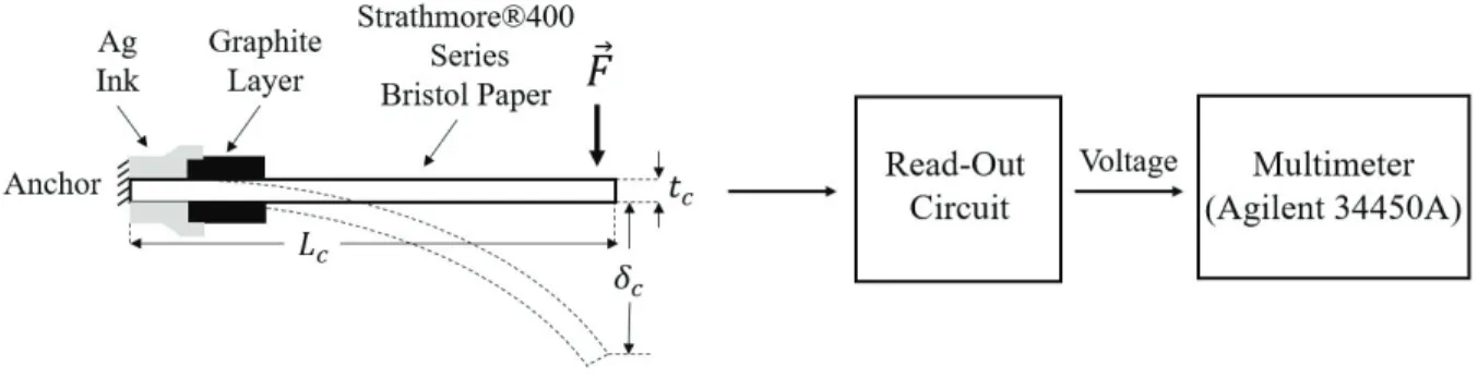
The designed weight-sensing system harbors three essential components. These are a disposable paper-based weight sensor, a simple read-out circuitry that is able to detect small changes in resistance stemming from stress occurring on the piezoresistive graphite layer, and a generic multimeter (Agilent 34450A). The underlying operation principle of the proposed system is illustrated in Figure1.
The proposed paper-based fixed-free cantilever beam whose top and bottom surfaces at the anchor point are coated with thin-film piezoresistive graphite layers is directly bent in the direction of the point-force ⃗F that
is exerted to the tip of the structure as delineated in Figure 1. The formula describing this relation between tip-displacement δc of the cantilever beam and the applied point-force |F | is given in Equation1from [29]:
δc=
4|F |Lc3
Ewctc3
, (1)
Figure 1. System diagram of the proposed weight-sensing system. System harbors a paper-based sensor along with a read-out circuit and a multimeter. Total resistance change arising from the applied force to tip of the cantilever beam is detected and then amplified using the implemented read-out circuitry and subsequently fed into a multimeter.
width, length, and thickness of the cantilever beam, respectively. The tip-displacement δc, whose magnitude
increases linearly with the amplitude of the exerted force, simultaneously creates both a tensile stress on the top piezoresistive graphite layer and a counter compressive stress on the bottom surface of the graphite layer (or vice versa) depending on the direction of the applied force. The maximum stress, σmax, occurring on the
graphite layer is given in Equation 2 [29–31]. Assuming that the thickness of the proposed sensing structure,
tc, is identical to the thickness of the main fabrication material, it can be said that one can carefully choose an
optimal value for length Lc and width wc of the proposed cantilever beam structure and attain a considerable
amount of augmentation in tensile and compressive stresses that are formed on the top and bottom piezoresistive layers as shown in Figure1. Maximum stress occurs at the fixed end of the cantilever and its magnitude linearly decreases towards the deflected end [30]:
σmax=
6|F |Lc
wctc2
. (2)
In conjunction with alternating mechanical stress, a resistance change of ∆R arises for each (top and bottom) piezoresistive graphite layer. These related resistance changes are detected and subsequently amplified using a single read-out circuitry that is simply composed of a Wheatstone bridge circuit and an instrumental amplifier (INA128). Acquired voltage signals are then delivered to a generic multimeter (Agilent 34450A), which ultimately ensures an accurate sensing of the applied force.
3. Proposed design
Figure2illustrates the proposed perforated paper-based weight sensor. Critical design parameters affecting the performance of the structure are precisely shown in the figure. The related values of these design parameters are given in Table 1. The paper-based sensing structure is designed in a such a way that the disposable device has an uncomplicated clean geometry easing the following fabrication and measurement steps. Therefore, a generic simple cantilever geometry is chosen for this study. Secondly, the stress occurring due to the applied force on the tip of the structure should be maximized in order to increase the sensitivity (mV/g). Therefore, the width
wc1 of the cantilever beam is continuously enlarged to wc2 as we move through the cantilever beam, from the
anchor to the tip-point, as shown in Figure 2a. This rise ensures a shift in the location of the center of the mass of the structure towards the tip, consequently creating an augmentation in the stress level. Finally, the
structure is designed to have its maximum stress formed in the direction of A− A′ as demonstrated in Figure
2a.
Figure 2. Technical illustration of the proposed sensing structure showing the design parameters: (a) top view of the structure, (b) close-up view of the perforated structure together with the graphite layer, (c) side view of the proposed sensing structure.
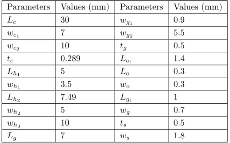
Table 1. Parameters and values of proposed design illustrate in Figure2.
Parameters Values (mm) Parameters Values (mm)
Lc 30 wg1 0.9 wc1 7 wg2 5.5 wc2 10 tg 0.5 tc 0.289 Lo1 1.4 Lh1 5 Lo 0.3 wh1 3.5 wo 0.3 Lh2 7.49 Lg1 1 wh2 5 wg 0.7 wh3 10 ts 0.5 Lg 7 ws 1.8
In order to benefit from the accumulating stress in the A−A′ direction, a serpentine-shaped piezoresistive
layer is preferred at that location as depicted in Figure2b. The resistor that is composed of the above-mentioned serpentine-shaped piezoresistive graphite film with a thickness of 50 µ m is precisely positioned 1 mm away from the fixed end of the paper-based structure with the main aim of optimally harvesting the resistance change. As Table 1 elaborates, the length ( Lg), width ( wg2), and thickness ( tg) of this layer are chosen as 700 µ m,
550 µ m, and 50 µ m, respectively. The tip of cantilever beam is designed to have an area of size proportionate to the apex of an index finger in order to facilitate the subsequent force-displacement characterization process. Therefore, the width of the tip of the cantilever ( wc2) is selected as 10 mm. Moreover, in order to get the
minimum possible width for the fixed end wc1 of the proposed cantilever beam and choose meaningful puncture
sizes, or in other words, for increasing the stress created at the anchor point, the sensitivity, minimum feature sizes, and fabrication limits were investigated. In that vein, the line width of the graphite layers ( wg) is chosen
to be 700 µ m, while dependently the width of the fixed end of the cantilever beam ( wc1) is selected as 7 mm
and finally the technology-limited puncture size ( Lo × wo) is preferred to be 400 µ m × 400 µm. Afterwards,
every other parameter that is tabulated in Table 1 is carefully selected in conjunction with the initial choice of wc2 without being oblivious to possible fabrication errors and the technology limits of our implementation
process, which will be elaborated in Section 6.
Moreover, as illustrated in Figure2a, there exists two nonoperational ears that are placed at the right-and left-hright-and sides of the Ag contact pads. These redundant surfaces are used to immobilize the structure onto the printed circuit board harboring the peripheral electronics circuits and to ensure a robust operation.
4. Simulation results
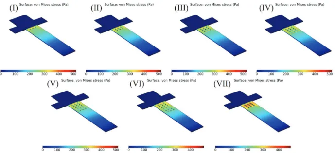
In the following step, the proposed designs are simulated to examine their performance. Figures3and4illustrate these finite-element method (FEM) simulations of the various perforation patterns.
Figure 3. Finite-element method simulation results of various perforation patterns for sensing structures showing the maximum stress values at the fixed end of the cantilever.
The main objective of these simulations is to evaluate which puncture topology has a stronger effect on augmenting the stress (σmax) at the anchor assuming a constant weight value (0.1 mg) exerted onto the tip
of the cantilever beam. Pertinent simulation results are tabulated in Table 2. At this point, it is critical to indicate that the puncture sizes are chosen considering the fabrication resolution and capabilities of the laser cutter that is used. The resolution of the Epilog Helix 24, 60 W, is tested and it is determined that a minimum of 400 µ m×400µm squares can be laser-cut without over-burning the edges.
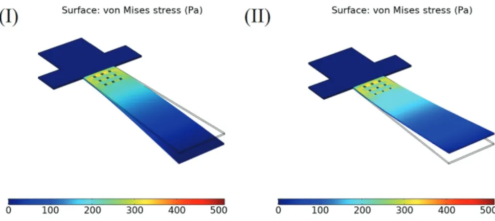
Figure 4. Simulation results of compressive (I) and tensile (II) behavior enlarging the perforated cantilever beam. Maximum stress value is observed as 518 Pa with 240.27 nm tip displacement. View of the stress density distribution on the paper-sensing structure as a result of applied weight to tip and its tip displacement are marked.
Table 2. FEM simulation results for various perforation patterns.
Design number Puncture size (µm× µm) Array size Anchor stress (Pa) Tip displacement (nm)
I 400× 400 3× 1 518 257.77 II 400× 400 3× 2 515 260.36 III 400× 400 3× 3 525 262.64 IV 400× 400 3× 4 516 264.66 V 400× 400 3× 5 514 266.30 VI 400× 400 3× 6 513 267.75 VII 400× 3800 3× 1 474 277.60
As can be deduced from the simulation results tabulated in Table 2, as the array size gets larger, the stress occurring at the anchor exhibits almost an inverted U-curve behavior, whereas the tip displacement of the cantilever beam continuously increases from approximately 257.77 nm to 277.60 nm. Even though acquiring a stress value as large as possible at the anchor for an applied force is the desired effect, one should also scrutinize the increase in tip displacement value and prevent the unnecessary bending of the cantilever beam. The reason for this consideration is twofold. First, the initial bending/displacement of the cantilever beam without exertion of external force must be negligible so that the final product will have a larger dynamic range of sensing. Secondly, having a larger initial bending affects the equilibrium between initial resistance values of the top (tensile) and bottom (compressive) piezoresistive layers, which are assumed to be equal for the subsequent electronic read-out circuit. For these reasons, design number III is selected as the optimum one since it not only keeps the balance between initial resistance values but also ensures a considerable increase of anchor-stress for an externally applied force.
Lastly, Figure4shows the FEM simulation results of the final proposed design for the paper-based sensing structure whose dimensions are tabulated in Table1. It must be stated that this paper-based sensing structure uses a 3×3 puncture array with a puncture size of 400 µm× 400 µm. It is shown through the simulation that
exerting 0.1 mg onto this structure produces a stress value of 518 Pa at the anchor point where the piezoresistive layer lies.
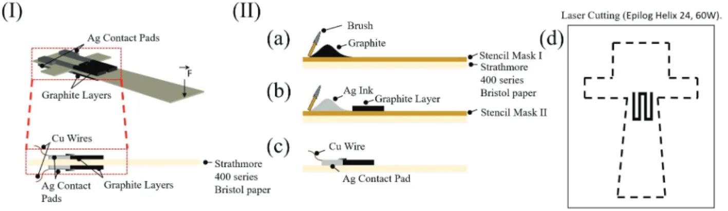
5. Implementation
Figure5shows various steps of the fabrication process of our proposed perforated paper-based disposable weight sensor. In this work, as the main fabrication material and the method, a 289- µ m-thick Strathmore 400 series Bristol paper and screen-printing are preferred. The predicted final conceptual view of the proposed sensing structure having two separate graphite layers located on the top and bottom surfaces of the paper cantilever beam, along with their Ag contact pads, is depicted in Figure5(inset I). As the first step, the silk stencil mask (mask I) shown in inset II-a having a pore size of 36 µ m and an approximate thickness of 48 µ m is utilized to apply the graphite paste onto both sides of the paper. In this work, an electrically highly resistant graphite paste (Bare Conductive ink, 55 Ω/Sq @ 50 microns) was selected considering its good adhesion and nontoxic, water-soluble properties. Graphite paste is skillfully applied to the Bristol paper by means of a rubber brush as depicted in inset II-a and 48- µ m-thick graphite is coated on the paper-based cantilever beam. Subsequently, silver electrical contact pads are formed resorting to a second stencil mask (mask II) as in Figure5 (inset II-b), again having the same pore size of 36 µ m and approximate thickness of 48 µ m together with a low-resistant silver paste (Gwent C2130809D5 Silver:Silver Chloride paste 60:40), which was selected considering its high conductivity and low curing temperature properties. The same prior procedure has been followed as illustrated in inset II-b to coat the electrical contact pads. The Ag layer of roughly 48 µ m thick is delicately coated to ensure electrical connectivity between the sensor and the read-out electronic circuitry.
Figure 5. (I) Three dimensional (3D) drawing of the proposed double-side perforated paper-based structure including a graphite layer and Ag contact pads. (II) Fabrication process of the double-side perforated paper-based sensor.
In order to obtain a double-sided structure as elaborated in Section 2, the same process is carefully duplicated on the other surface of the cantilever beam after a sensitive alignment step. In the final step, the cantilever beam is precisely cut employing the help of a laser cutter (Epilog Helix 24, 60 W). The fabrication process is concluded by connecting Cu wires to Ag pads to ensure electrical connectivity as in Figure 5 (inset II-c).
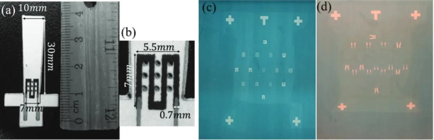
The fabricated perforated paper-based structure is shown in Figure 6a and a close-up view of the top surface of the graphite and Ag-coated structure is shown on the right-hand side of Figure 6b along with its measurement dimensions. Close-up views of the aforementioned stencil mask I and stencil mask I are depicted in Figures6c and6d.
Figure 6. (a) View of the fabricated paper-based force sensor and (b) close-up view of the serpentine piezoresistive layer with 400 µ m × 400µm perforated structures. (c) Close-up view of the graphite layer mask (stencil mask I) and
(d) close-up view of the Ag contact pads mask (stencil mask II).
6. Electronic read-out circuitry
As shown in Figure5, the proposed sensing system has two thin-film graphite layers that are separately coated on the top and bottom surfaces of the same cantilever beam, whereas a typical piezoresistive pressure/weight sensor [16–18] employs just one thin-film layer to detect the resistance changes caused by exerting force through mass m⃗g . Assuming that the alternating resistance values of the top and bottom graphite layers due to the utilized mass are + ∆R and - ∆R , one may successively employ Wheatstone bridge circuitry with two varying resistors and then an instrumentation amplifier, as illustrated in Figure 7a, in order to be able to detect the slightest resistance changes + ∆R and - ∆R [32]. Output voltage of the proposed read-out system is stated in Equation3, with G being the gain of the instrumentation amplifier:
Figure 7. (a) Electronic read-out circuit that consists of a Wheatstone bridge circuit with two inversely changing graphite resistors and a subsequent instrumentation amplifier, INA128, to further amplify the voltage signal acquired trough the resistance change. Top (b) and bottom (c) views of the printed circuit board for the proposed electronic read-out circuit. Implemented PCB has dimensions of 26 mm × 22 mm.
VOU T =
VIN
2 ∆R
R G. (3)
The main objective of the Wheatstone bridge circuit in this system is to detect the unknown value of ∆R , which is actually the resistance change of the thin-film graphite layers [17]. At the beginning, the circuit
calibrates the system output by balancing the two branches of the bridge circuit and by ensuring to initially acquire a zero-volt output when there is no bending. Since the sensing structure begins to be bent and the tip displacement δc starts to gradually increase as a consequence of the exerted mass m⃗g , the value of ∆R begins
to augment and correspondingly the circuit becomes unbalanced and an output voltage starts to emerge. As shown in Figure7a, a Wheatstone bridge circuit having two inversely changing resistors R + ∆R and R− ∆R
is chosen in this study. Immediately after the mass m⃗g acts on the tip of the paper-based cantilever beam, the arising bending forms a tensile and a compressive stress on the top and bottom graphite layers, respectively. These opposing types of stress cause + ∆R and - ∆R changes in the proposed circuit [33,34].
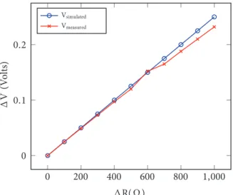
0 200 400 600 800 1,000 0 0.1 0.2 ∆ R( Ω ) ∆ V (V olts) Vsimulated Vmeasured
Figure 8. Plot of the output voltage change ( ∆ V) as a function of resistance change ( ∆ R). Blue line corresponds to simulation results of proposed read-out circuit, whereas red line corresponds to measurement results of system with implemented PCB.
Distinct from conventional Wheatstone bridge circuits, having two conversely differentiating resistors that unbalance the bridge in the circuit inherently increases the gain of the systems’ transfer function by twofold as stated in Equation3. To further increase the sensitivity of the system, an instrumentation amplifier (INA128) is attached to the output of the Wheatstone bridge circuit [35,36]. The amplifier is designed to possess a voltage gain of G , which is equal to 100 V/V. The output voltage that is formed at the output of the circuit as a result of increased stress in the graphite piezoresistive layer is then amplified via the instrumentation amplifier and fed into a digital multimeter. The proposed electronic read-out circuit is implemented using surface mount devices as a printed circuit board (PCB) and is shown in Figures7b and 7c. The length and width of the board are 26 mm and 22 mm, respectively. The proposed electronic read-out circuit is simulated with LTspice software for an increasing value of R and the simulation result is shown in Figure8 as Vsimulated. It is also tested with an
implemented PCB and the measurement result is indicated as Vmeasured. On the other hand, the test setup
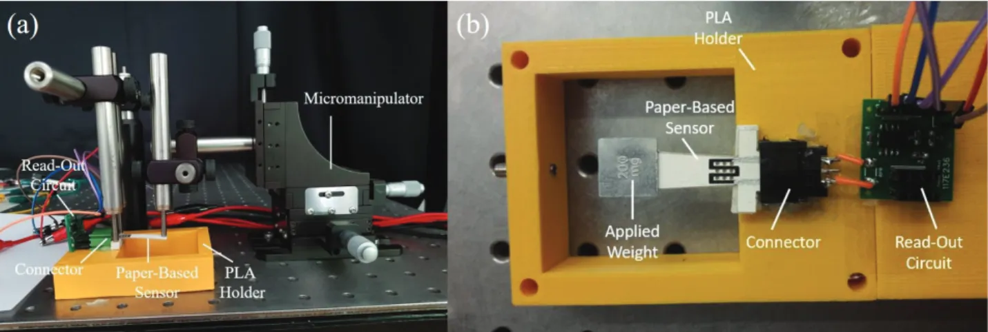
shown in Figure 9a is designed to detect the stress level and corresponding resistance change values caused by the force generated by using different weights at the free end of the paper-based structure. Experimental data are collected by following the same procedure. Figure 10plots the normalized resistance change ∆ R/R of the proposed weight-sensing systems under the application of an increasing point-force that causes a linear rise of the tip displacement value.
Figure 9. (a) Experimental test setup to monitor the tip displacement versus the normalized resistance change of the proposed sensing system. (b) View of the experimental setup for the proposed force-sensing system with an applied weight. 0 500 1,000 1,500 2,000 2,500 3,000 0 1 2 3 4 5 ·10−2 Displacement (µm) ∆ R/ R (Ω /Ω ) S.B. 400 series A.S. background A.S. tech. draw. A.S. met. background A.S. tracing
Figure 10. Plot of the normalized resistance change ( ∆ R/R) for increasing tip displacement ( δc). Red, pink, blue, cyan, and black lines show that behavior of different papers. They correspond to Strathmore 400 series Bristol paper, Alex Schöller background paper, Alex Schöller technical drawing paper, Alex Schöller metallized background paper, and Alex Schöller tracing paper.
7. Experimental results
In the following step, the proposed sensing system is tested. The test setup that is used to monitor the behavior of the designed and implemented system is shown in Figure9a. The former shows the devised test setup that monitors the change in resistance occurring in the piezoresistive layer. It was previously explained that the level of resulting stress at the anchor point of the paper-based structure increases in direct proportion to the amount of tip displacement ( δc) caused by the bending of the paper structure.
As shown in Figure9a, the paper-based structure is fixed onto a platform using a three-dimensional (3D) printed holder made out of PLA (polylactic acid) filament. The tip displacement at the free-end point of the
paper is formed by means of the micromanipulator, which has motion sensitivity of 5 µ m. The paper-based cantilever beam is getting slowly bent through the micromanipulator and dependently the stress value at the anchor is gradually raised. The stress levels and the resistance change values occurring on the graphite layer are transmitted to the read-out circuit through the connector, which is fixed to the PLA holder via Ag contact pads.
In this test, the effects of using different kinds of fabrication materials such as Strathmore 400 series Bristol paper, Alex Schöller background paper, Alex Schöller technical drawing paper, Alex Schöller metallized background paper, and Alex Schöller tracing paper are investigated. When the tip displacement( δc) value
is gradually increased from 0 to 3000 µ m with the help of the micromanipulator as indicated in Figure 9a, normalized resistance change ( ∆R/R) of the Strathmore 400 series Bristol paper is monitored and it is seen that the normalized resistance change linearly increases from 0 to 0.04982 Ω/Ω as emphasised in Figure 10.
Moreover, it is also reported for the other cantilever beams that when their tip displacements ( δc) are
increased from 0 to 3000 µ m, normalized resistance changes ( ∆R/R) increase from 0 to 0.02588 Ω/Ω , 0.02389 Ω/Ω , 0.04480 Ω/Ω , and 0.01167 Ω/Ω for Alex Schöller background paper, Alex Schöller technical drawing paper, Alex Schöller metallized background paper, and Alex Schöller tracing paper, respectively, as shown in Figure 10.
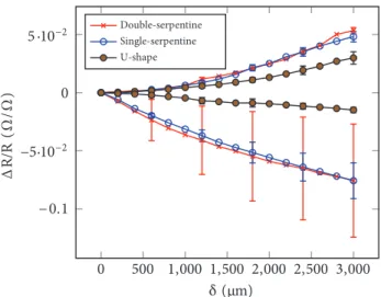
According to the test results, the Strathmore 400 series Bristol paper having magnitude of 0.04982 Ω/Ω , which is the maximum normalized resistance change ( ∆R/R) value without having any plastic deformation for the paper-based structure, is selected among all the other paper-based fabrication materials. Furthermore, Figure 11 plots the alternating normalized resistance changes versus the tip displacement with an emphasis on the effect of changing piezoresistive layers both in number and topology. In this plot, the change in the negative direction represents the resistance change due to compressive stress, whereas the change in the positive direction corresponds to the change in resistance through tensile stress. As the experimental results show, the single-serpentine piezoresistive layer design is stable and linear, but on the other hand it has a similar sensitivity compared to the double-serpentine structure. Thus, we resorted to the single-serpentine shaped piezoresistive layer in the final implementation.
8. Discussion
The aim of this study is to design and manufacture a paper-based disposable weight sensor with improved sensitivity. Numerous fabrication methods and materials are compared in the literature. It that vein, it has been reported that the paper-based structures are more suitable for creating disposable devices since they are easy to fabricate, abundant, and cheap.
As elucidated above, in this work, we propose a quick-to-fabricate paper-based, perforated cantilever beam having two single-serpentine shaped piezoresistive layers to measure applied weight. Figure 12 clearly shows that the perforated sensor having a double-sided piezoresistive layer has a higher sensitivity level (17.13 mV/mN) compared to the generic nonperforated paper-based sensor with a single sensing layer (0.84 mV/mN). In this work, the sensitivity of a simple paper-based weight sensor [17] is improved almost 20 times using the proposed methods. The sensitivity of a cheaper paper-based sensor used with old-fashioned and unrepeatable fabrication methods [18] is enhanced almost 19 times using ours. A concise comparison between this work and the works reported in [17] and [18] is tabulated in Table3.
0 500 1,000 1,500 2,000 2,500 3,000 −0.1 −5·10−2 0 5 ·10−2 δ (µm) ∆ R/ R (Ω /Ω ) Double-serpentine Single-serpentine U-shape
Figure 11. Plot of the normalized resistance change for increasing tip displacement. Since the proposed sensing structure has two piezoresistive layers, one being located above and the other below the paper-based structure, the plots are almost symmetrical along the ∆ R/R=0 line considering the opposing stresses (tensile and compressive) forming in respective layers. 0 500 1, 000 1, 500 2, 000 0 0. 1 0. 2 0. 3 0. 4 mass (milligrams) ∆ V (V olts) Double PR layer Single PR layer
Figure 12. Plot of the output voltage change ( ∆ V) as a function of the applied mass. Red line corresponds to mass-dependent voltage change of a paper-based sensor with a single-sided screen-printed piezoresistive (PR) layer, whereas blue line corresponds to the one with a two-side screen-printed piezoresistive layer. The one having a double-sided PR layer has 168.01 mV/g (=17.13 mV/mN) sensitivity, whereas the one with the single-sided PR layer has 85.13 mV/g (=8.68 mV/mN) sensitivity.
9. Conclusion
In this work, a paper-based perforated disposable weight sensor system with double piezoresistive layer has been designed, fabricated, and characterized along with the peripheral electronic circuit. The demonstrated system is designed to achieve a highly sensitive weight-sensing operation with low-cost materials. For that purpose, the main fabrication material of the proposed disposable sensor is chosen as 289- µ m-thick Strathmore 400 series Bristol paper. Approximately 48- µ m-thick piezoresistive graphite paste is coated onto both sides of the paper-based cantilever beam with the aim of acquiring more sensitive weight-sensing capability. Additionally,
Table 3. Comparison of specifications of our paper-based weight sensor to the works in [17] and [18].
Specifications This Work Reference [17] Reference [18] 1. Substrate Strathmore 400 series
Bristol paper (289 µm thick) Whatman 3MM chromatography paper (340 µm thick) A4 paper (88 µm thick)
2. Pattern method for substrate
Laser equipment Laser equipment (Epilog Helix 24, 60 W) Scissors 3. Beam size L× (w1– w2)× t 30 mm × (7-10 mm) × 0.289 mm 44.5 mm × 7.7 mm × 0.34 mm 45 mm × 8 mm × 0.088 mm 4. Young’s modulus 2.388 GPa 1.98± 0.17 GP a 0.03 GPa 5. Force & mass ranges 2 g (19.6 mN) 16 mN 50 mN 6. Force & mass
resolutions
20 mg (196 µN) 120 µN 500 µN
7. Sensitivity 168.01 mV/g (17.13 mV/mN)
0.84 mV/mN 0.9 mV/mN 8. Sensing material Graphite (Bare Conductive
Electric Paint)
Graphite ink Graphite pencil 9. Pattern method for
sensing material
Silk screen-printing Silk screen-printing Hand-drawing 10. Electrode material Ag ink (Gwent
C2130809D5:Silver Chloride paste 60:40)
Ag ink Copper foil
11. Fabrication process <10 min in laboratory <1 h in laboratory <30 min in any place 12. Device cost <$0.04 per device $0.04 per device $0.01 per device
the proposed paper-based structure has rows of closely spaced perforation at prespecified locations to facilitate the bending of the cantilever beam and to further increase the sensitivity of the system. A peripheral electronic read-out circuitry is developed and integrated into the system. It is experimentally demonstrated that the proposed weight-sensing system can measure miniature weights ranging to 2 g with a resolution of 20 mg and costs under $0.04 per device. The implemented sensor has sensitivity of 17.13 mV/mN or 168.01 mV/g. We showed that the sensitivity of a simple paper-based weight sensor is improved almost 20 times using the proposed methods.
Acknowledgment
This work was funded by TÜBİTAK EEEAG, Project No: 117E236. The authors would like to sincerely thank TÜBİTAK and research group members Öznur Mete, Elif Teker, Batuhan İstanbullu, Berkay Alçiçek, and Berfin Gedlaç.
References
[1] Dobrzynska JA, Gijs MAM. Flexible polyimide-based force sensor. Sensors and Actuators A: Physical 2012; 173 (1): 127-135. doi: 10.1016/j.sna.2011.11.006
[2] Lee HK, Chung J, Chang SI, Yoon E. Normal and shear force measurement using a flexible polymer tactile sensor with embedded multiple capacitors. Journal of Microelectromechanical Systems 2008; 17 (4): 934-942. doi: 10.1109/JMEMS.2008.921727
[3] Bonomo C, Fortuna L, Giannone P, Graziani S, Strazzeri S. A resonant force sensor based on ionic polymer metal composites. Smart Materials and Structures 2007; 17 (1): 015014. doi: 10.1088/0964-1726/17/01/015014
[4] Lee, HK, Chung J, Chang SI, Yoon E. Real-time measurement of the three-axis contact force distribution using a flexible capacitive polymer tactile sensor. Journal of Micromechanics and Microengineering 2011; 21 (3): 035010. doi: 10.1088/0960-1317-21-3-035010.
[5] Hasenkamp W, Forchelet D, Pataky K, Villard J, Van LH et al. Polyimide/SU-8 catheter-tip MEMS gauge pressure sensor. Biomedical Microdevices 2012; 14 (5): 819-828. doi: 10.1007/s10544-012-9661-8
[6] Crum B, Li W. Parylene-based fold-and-bond wireless pressure sensor. In: The 8th Annual IEEE International Conference on Nano/Micro Engineered and Molecular Systems; Suzhou, China; 2013. pp. 1155-1158.
[7] Su YF, Kotian RR, Lu N. Energy harvesting potential of bendable concrete using polymer based piezoelectric generator. PComposites Part B: Engineering 2018; 153: 124-129. doi: 10.1016/j.compositesb.2018.07.018
[8] Wang X, Sun F, Yin G, Wang Y, Liu B, Dong M. Tactile-sensing based on flexible PVDF nanofibers via electro-spinning: a review. Sensors 2018; 18 (2): 330. doi: 10.3390/s18020330
[9] Steffens C, Brezolin AN, Steffens J. Conducting polymer-based cantilever sensors for detection humidity. Scanning 2018; 6: 4782685. doi: 10.1155/2018/4782685
[10] Nambiar S, Yeow JTW. Conductive polymer-based sensors for biomedical applications. Biosensors and Bioelectron-ics 2011; 26 (5): 1825-1832. doi: 10.1016/j.bios.2010.09.046
[11] Plum TJ, Saxena V, Jessing RJ. Design of a MEMS capacitive chemical sensor based on polymer swelling. In: 2006 IEEE Workshop on Microelectronics and Electron Devices; Boise, ID, USA; 2006. pp. 49-50.
[12] Kumar N, Piccin O, Meylheuc L, Barbé L, Bayle B. Design and modeling of a polymer force sensor. IEEE/ASME Transactions on Mechatronics 2015; 21 (1): 555-564. doi: 10.1109/TMECH.2015.2448662
[13] Pyo S, Lee JI, Kim MO, Lee HK, Kim J. Polymer-based flexible and multi-directional tactile sensor with multiple NiCr piezoresistors. Micro and Nano Systems Letters 2019; 7 (1): 1-20. doi: 10.1186/s40486-019-0085-6
[14] Cheng MY, Lin CL, Lai YT, Yang YJ. A polymer-based capacitive sensing array for normal and shear force measurement. Sensors 2010; 10 (11): 10211-10225. doi: 10.3390/s101110211
[15] Shu Y, Li C, Wang Z, Mi W, Li Y et al. A pressure sensing system for heart rate monitoring with polymer-based pressure sensors and an anti-interference post processing circuit. Sensors 2015; 15 (2): 3224-3235. doi: 10.3390/s150203224
[16] Liu XY, O’Brien M, Mwangi M, Li XJ, Whitesides GM. Paper-based piezoresistive MEMS force sensors. In: 2011 IEEE 24th International Conference on Micro Electro Mechanical Systems; Cancun, Mexico; 2011. pp. 133-136. [17] Liu X, Mwangi M, Li X, O’Brien M, Whitesides GM. Paper-based piezoresistive MEMS sensors. Lab on a Chip
2011; 11 (13): 2189-2196. doi: 10.1039/C1LC20161A
[18] Ren TL, Tian H, Xie D, Yang Y. Flexible graphite-on-paper piezoresistive sensors. Sensors 2012; 12 (5): 6685-6694. doi: 10.3390/s120506685
[19] Phan HP, Dao DV, Dinh T, Brooke H, Qamar A et al. Graphite-on-paper based tactile sensors using plastic laminating technique. In: 2015 28th IEEE International Conference on Micro Electro Mechanical Systems; Estoril, Portugal; 2015. pp. 825-828.
[20] Crowley K, Nakidde D, Travis J, Agah M. Paper-based MEMS hair cell array. In: SENSORS, IEEE; Baltimore, MD, USA; 2013. pp. 1-4.
[21] Qian Q, Wang Y, Zhang M, Chen L, Feng J et al. Ultrasensitive paper-based polyaniline/graphene com-posite strain sensor for sign language expression. Comcom-posites Science and Technology 2019; 181: 1-20. doi: 10.1016/j.compscitech.2019.05.017
[22] Yu Z, Tang Y, Cai G, Ren R, Tang D. Paper electrode-based flexible pressure sensor for point-of-care immunoassay with digital multimeter. Analytical Chemistry 2018; 91 (2): 1222-1226. doi: 10.1021/acs.analchem.8b04635 [23] Fastier WJ, Dinh T, Dau V, Phan HP, Yang F et al. Low-cost graphite on paper pressure sensor for a robot gripper
with a trivial fabrication process. Sensors 2018; 18 (10): 3300. doi: 10.3390/s18103300
[24] Wu Y, Karakurt I, Beker L, Kubota Y, Xu R et al. Piezoresistive stretchable strain sensors with human machine interface demonstrations. Sensors and Actuators A: Physical 2018; 279: 46-52. doi: 10.1016/j.sna.2018.05.036 [25] Stassi S, Cauda V, Canavese G, Pirri C. Flexible tactile sensing based on piezoresistive composites: a review.
Sensors 2014; 14 (3): 5296-5332. doi: 10.3390/s140305296
[26] Lin X, Gao S, Fei T, Liu S, Zhao H et al. Study on a paper-based piezoresistive sensor applied to monitoring human physiological signals. Sensors and Actuators A: Physical 2019; 292: 66-70. doi: 10.1016/j.sna.2019.04.009
[27] Turner A, Karube I, Wilson GS. Biosensors: Fundamentals and Applications. New York, NY, USA: Oxford University Press, 1987.
[28] Sanli A, Ramalingame R, Kanoun O. Piezoresistive pressure sensor based on carbon nanotubes/epoxy composite under cyclic loading. In: 2018 IEEE International Instrumentation and Measurement Technology Conference; Houston, TX, USA; 2018. pp. 1-5.
[29] Young WC, Budynas RG, Sadegh AM. Roark’s Formulas for Stress and Strain. New York, NY, USA: McGraw-Hill, 2002.
[30] Liu C. Foundations of MEMS. Upper Saddle River, NJ, USA: Prentice Hall, 2012. [31] Senturia SD. Microsystem Design. Boston, MA, USA: Kluwer Academic Publishers, 2001.
[32] Ayraç T, Gökdel YD. A read-out system for disposable paper-based sensors. In: 2018 3rd International Conference on Computer Science and Engineering; Sarajevo, Bosnia-Herzegovina; 2018. pp. 386-389.
[33] Khan SA, Islam T. Precision active bridge circuit for measuring incremental resistance with ANN compensation of excitation voltage variation. Journal of Sensor Technology 2011; 1 (3): 57-64. doi: 10.4236/jst.2011.13008
[34] Kester W. Practical Design Techniques for Sensor Signal Conditioning. New York, NY, USA: Analog Devices, 1999. [35] Madzhi NK, Khuan LY, Abdullah MF, Ahmad A. Development of a low cost self-sensing piezoresistive micro-cantilever biosensor and read-out circuitry for measuring salivary-amylase activity. In: 2010 2nd International Conference on Electronic Computer Technology; Kuala Lumpur, Malaysia; 2010. pp. 9-13.
[36] Anuar AFM, Johari S, Wahab Y, Zainol MZ, Fazmir H et al. Development of a read-out circuitry for piezoresistive microcantilever electrical properties measurement. In: 2015 IEEE Regional Symposium on Micro and Nanoelec-tronics (RSM); Kuala Terengganu, Malaysia; 2015. pp. 1-4.
![Table 3. Comparison of specifications of our paper-based weight sensor to the works in [ 17 ] and [ 18 ].](https://thumb-eu.123doks.com/thumbv2/9libnet/4266842.68309/13.918.106.814.170.645/table-comparison-specifications-paper-based-weight-sensor-works.webp)
