Yildiz Technical University Press, Istanbul, Turkey
This paper was recommended for publication in revised form by Regional Editor Hakan Demir
1Department of Mechanical Engineering, Bursa Technical University, Bursa, Turkey
*E-mail address: [email protected] Orcid id: 0000-0003-3421-2020
Manuscript Received 25 January 2018, Accepted 06 April 2018
NUMERICAL INVESTIGATION OF LAMINAR MIXED CONVECTION IN A SQUARE
CROSS-SECTIONED CYLINDRICAL ANNULAR ENCLOSURE
Osman Turan1,*
ABSTRACT
Steady-state laminar mixed convection of Newtonian fluids in a square cross-sectioned cylindrical annular enclosure with rotating inner wall and heated top cover has been numerically analysed based on axisymmetric incompressible flow simulations. Richardson number, Reynolds number and 𝑟𝑖/𝑅 effects on heat and momentum
transport have been investigated for the range of Richardson number 0 ≤ 𝑅𝑖 ≤ 1, Reynolds number 500 ≤ 𝑅𝑒 ≤ 2000 and 0.25 ≤ 𝑟𝑖/𝑅 ≤ 8 at a representative value of Prandtl number (i.e. 𝑃𝑟 = 1.0). A scaling
analysis has been also carried out in order to elucidate the possible influences of Reynolds, Richardson and Prandtl numbers and 𝑟𝑖/𝑅 on the mean Nusselt number. It has been found that the mean Nusselt number 𝑁𝑢̅̅̅̅ demonstrates a
monotonically decreasing trend with increasing 𝑅𝑖 whereas 𝑁𝑢̅̅̅̅ increases with increasing 𝑟𝑖/𝑅 and 𝑅𝑒 which is
consistent with scaling estimation. It is also observed that the flow pattern in the case of purely forced convection (i.e. 𝑅𝑖 = 0) is significantly different from those in mixed convection (i.e. 𝑅𝑖 > 0). In the case of 𝑅𝑖 = 0 (i.e. purely forced convection), a one-cell flow structure with two small vortexes on the top corners is observed for 𝑟𝑖/𝑅 ≤ 1,
whereas a second cell appears in the flow field for 𝑟𝑖/𝑅 > 1 at 𝑅𝑒 = 1000. On the other hand, in the case of mixed
convection (i.e. 𝑅𝑖 > 0), two-cell and four-cell flow structures occur in the flow field depending on 𝑅𝑖 and 𝑟𝑖/𝑅 for
the range of 𝑅𝑖, Re and 𝑟𝑖/𝑅 considered here at 𝑃𝑟 = 1.0. Based these observations, a flow regime diagram has been
proposed here for mixed convection (i.e. 𝑅𝑖 > 0) for the range of 𝑅𝑖, 𝑅𝑒 and 𝑟𝑖/𝑅 analysed in this study.
Keywords: Mixed Convection, Rotating Wall, Richardson number, Cylindrical Enclosure, Annular Enclosure
INTRODUCTION
Mixed convection in a cylindrical container with rotating one of the wall has been extensively analysed due to its wide range of applications such as chemical processing, bio-chemical synthesis, polymer processing, food preparation, pharmacology. In these applications, mixed convection plays a vital role not only in heat transfer rate but also influences the mixing rate for low Reynolds number cases. Therefore, it is necessary to investigate heat transfer characteristics and flow structure in this configuration so that the rates of heat transfer and mixing can be optimised. However, heat transfer and mixing rates in this configuration depend on many parameters such as container geometry and the rotational speed of the wall. Two special cases of rotating flow problems which are the flows on top a rotating disk and inside an enclosure with a rotating one of the end covers have been commonly investigated in the current literature. Theodore von Karman pioneered the analysis of flows on top a rotating disk and such flows are commonly referred to as von-Karman flows, and an extensive review of such flows is provided in Ref. [1]. In addition to this, flow in cylindrical enclosures with a rotating cover has also been extensively analysed from various different viewpoints due to its wide range of roles in a range of different engineering applications. Vogel [2,3], Ronnenberg [4] and Bertela and Gori [5] analysed fluid flows in cylindrical enclosures with a rotating end wall, and the findings of these studies [1-4] have subsequently been extended by Escudier [6] based on an experimental analysis where the criterion for vortex breakdown has been proposed in terms of aspect ratio H/R and Reynolds number Ω𝑅2/𝜈. Besides
these experimental studies, several numerical investigations [7-12] analysed fluid flows in cylindrical enclosures with a rotating end wall. The flow produced in a conical container by a rotating end wall has also been numerically analysed by Escudier et al. [12] who reported that vortex breakdown is suppressed beyond a certain angle of inclination of the sidewall for both convergent (increasing radius towards the rotating end wall) and divergent (decreasing radius towards the rotating end wall) geometries.
The analysis of heat transfer characteristics in cylindrical enclosures with a rotating cover received relatively limited attention [9-11]. Lee and Hyun [10] analysed the effects of Prandtl number on heat transfer rate in this configuration and revealed that Prandtl number has an important influence on the heat transfer characteristics and advective transport has been found to strengthen with increasing Prandtl number. Iwatsu [11] investigated the effects of Reynolds and Richardson numbers at Pr = 1, in the range of 100 ≤ Re ≤ 3000, and 0 ≤ Ri ≤ 1, on the flow pattern
Journal of Thermal Engineering, Research Article, Vol. 6, No. 1, pp. 1-15, January, 2020
2
and heat transfer rate for swirling flows in cylindrical enclosures with an aspect ratio of unity (i.e. AR = H/R = 1), and a heated rotating top wall based on numerical simulations. The analysis by Iwatsu [11] revealed that advective (diffusive) transport strengthens (weakens) and accordingly, the mean Nusselt number increases with decreasing Richardson number. Existing analyses on flow induced by the rotation of one of the end covers in a cylindrical enclosure have been also summarised in a recent paper by Turan et al. [13] according to the boundary conditions, the governing non-dimensional parameters and the nature of the investigation (i.e. whether it is experimental or numerical).
Majority of the investigations in the existing literature related to mixed convection in enclosure spaces have been carried out for rectangular enclosure with rotating top or bottom cover. Although cylindrical annular space with rotating inner wall is more relevant to real engineering applications than rectangular enclosures with rotating top or bottom cover (especially in mixing processes), there is no study where laminar mixed convection of Newtonian fluids in cylindrical annular enclosures has been analysed in detail in existing literature. This gap in existing literature has been addressed here by numerically analysing mixed convection of Newtonian fluids in a square cross-sectioned cylindrical annular enclosure with rotating inner wall and heated top cover for the range of Richardson and Reynolds numbers 0 ≤ 𝑅𝑖 ≤ 1 and 500 ≤ 𝑅𝑒 ≤ 2000 respectively for 0.25 ≤ 𝑟𝑖/𝑅 ≤ 8 at a representative value of
Prandtl number (i.e. 𝑃𝑟 = 1.0). In this respect, the main objective of the present paper is to demonstrate the influences of Richardson and Reynolds numbers and 𝑟𝑖/𝑅 on mixed convection induced by a rotating inner wall in a cylindrical
annular enclosure with an aspect ratio of unity.
The rest of the article will be organised as follows. The necessary mathematical background and numerical implementation will be discussed in the next section, which will be followed by a detailed scaling analysis. Following these sections, results will be presented and subsequently discussed. The main findings are summarised and conclusions are drawn in the final section.
MATHEMATICAL BACKGROUND
Governing equations and boundary conditions
In this study, the flow is assumed to be laminar, incompressible, steady and axisymmetric (i.e. two-dimensional). The conservation equations in the cylindrical coordinate system take the following form for steady-state incompressible axisymmetric swirling flows:
Mass conservation equation
𝜕𝑢 𝜕𝑟+ 𝑢 𝑟+ 𝜕𝑤 𝜕𝑧 = 0 (1)
Momentum conservation equations 𝜌 (𝑢𝜕𝑢 𝜕𝑟− 𝑣2 𝑟 + 𝑤 𝜕𝑢 𝜕𝑧) = − 𝜕𝑝 𝜕𝑟+ 𝜇 [ 1 𝑟 𝜕 𝜕𝑟(𝑟 𝜕𝑢 𝜕𝑟) − 𝑢 𝑟2+ 𝜕2𝑢 𝜕𝑧2] (2a) 𝜌 (𝑢𝜕𝑣 𝜕𝑟+ 𝑢𝑣 𝑟 + 𝑤 𝜕𝑣 𝜕𝑧) = 𝜇 [ 1 𝑟 𝜕 𝜕𝑟(𝑟 𝜕𝑣 𝜕𝑟) − 𝑣 𝑟2+ 𝜕2𝑣 𝜕𝑧2] (2b) 𝜌 (𝑢𝜕𝑤 𝜕𝑟 + 𝑤 𝜕𝑤 𝜕𝑧) = − 𝜕𝑝 𝜕𝑧+ 𝜌𝑔𝛽(𝑇 − 𝑇𝑟𝑒𝑓) + 𝜇 [ 1 𝑟 𝜕 𝜕𝑟(𝑟 𝜕𝑤 𝜕𝑟) + 𝜕2𝑤 𝜕𝑧2] (2c)
Energy conservation equation 𝜌𝑐𝑝(𝑢 𝜕𝑇 𝜕𝑟+ 𝑤 𝜕𝑇 𝜕𝑧) = 𝑘 ( 1 𝑟 𝜕𝑇 𝜕𝑟+ 𝜕2𝑇 𝜕𝑟2+ 𝜕2𝑇 𝜕𝑧2) (3)
where 𝜇 is the dynamic viscosity, 𝑇𝑟𝑒𝑓 is the reference temperature for evaluating the buoyancy term 𝜌𝑔𝛽(𝑇 − 𝑇𝑟𝑒𝑓)
in the momentum conservation equation in the vertical direction, and here 𝑇𝑟𝑒𝑓 is taken to be the cold cover temperature
𝑇𝑐. In addition, thermo-physical properties (thermal conductivity, specific heat, viscosity etc.) are considered to be
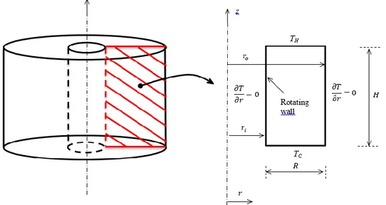
constant and independent of temperature in this analysis for the sake of implicitly. The numerical investigation is carried out for an axisymmetric domain which is schematically shown in Figure 1. The aspect ratio (AR = H/R) of the cylindrical container is considered to be unity (i.e. AR = H/R = 1). The bottom and top covers of the cylindrical
3
enclosures are kept at different temperatures (𝑇𝐶 < 𝑇𝐻), while the cylindrical surface is considered to be adiabatic in
nature. The temperature difference between the top and bottom covers are maintained small enough to ensure that Boussinesq approximation remains valid. No-slip boundary condition and impenetrable walls indicate that all the velocity components are identically zero at the non-rotating walls. For the rotating inner wall, radial and axial velocity components are identically zero due to impenetrability and no-slip conditions, and the tangential velocity component is given by 𝑉~𝛺𝑅(1 + 𝑟𝑖/𝑅).
Figure 1. Schematic diagrams of the simulation domain Non-dimensional numbers
The ratio between inertial and viscous forces represents the strength of the forced convection component in this analysis. This ratio can be quantified by the Reynolds number Re which is defined as:
𝑅𝑒 = 𝜌Ω𝑅
2
𝜇 (4)
The natural convection component of mixed convection can be characterised by the Grashof number, which represents the ratio of buoyancy to viscous forces, in the following manner:
𝐺𝑟 = 𝜌
2𝑔𝛽Δ𝑇𝐻3
𝜇2 (5)
Another important non-dimensional number is Rayleigh number, Ra, which demonstrates that the ratio of the strengths of thermal transports due to buoyancy to thermal diffusion, which is defined here in the following manner:
𝑅𝑎 = 𝜌
2𝑐
𝑝𝑔𝛽Δ𝑇𝐻3
𝜇𝑘 = 𝐺𝑟𝑃𝑟 (6)
where Pr is the Prandtl number, which is defined as: 𝑃𝑟 = 𝜇𝑐𝑝
𝑘 (7)
Prandtl number shows the ratio of momentum diffusion to thermal diffusion. The Prandtl number also represents the ratio of the hydrodynamic boundary layer to thermal boundary layer thicknesses. In addition to this, Richardson number is a well-known non-dimensional parameter for mixed convection, which is used to evaluate the relative importance of the natural to forced convection:
Journal of Thermal Engineering, Research Article, Vol. 6, No. 1, pp. 1-15, January, 2020 4 𝑅𝑖 = 𝐺𝑟 𝑅𝑒2= 𝑔𝛽Δ𝑇𝐻3 Ω2𝑅4 (8)
The rate of convective heat transfer is generally characterised by the heat transfer coefficient h, which is expressed in a non-dimensional form in terms of the Nusselt number Nu, as:
𝑁𝑢 =ℎ𝑅
𝑘 (9)
and the heat transfer coefficient h is defined as:
ℎ = |−𝑘𝜕𝑇 𝜕𝑧|𝑤𝑓
× 1
𝑇𝑤𝑎𝑙𝑙− 𝑇𝑟𝑒𝑓𝑓
| (10)
where subscript ‘wf’ refers to the condition of the fluid in contact with the wall, Twall is the wall temperature and Tref
is the appropriate reference temperature, which can be taken to be TC (TH) for the hot (cold) wall respectively. For this
configuration the mean heat transfer coefficient ℎ̅ and 𝑁𝑢̅̅̅̅ are given by: ℎ̅ = ∫ ℎ2𝜋𝑟𝑑𝑟/𝜋(𝑟𝑜2− 𝑟𝑖2) 𝑟𝑜
𝑟𝑖 and
𝑁𝑢
̅̅̅̅ = ℎ̅𝑅/𝑘, respectively.
Numerical implementation, grid-independency, and bench-marking
In this study, the conservation equations of mass, momentum and energy have been solved in the framework of a finite-volume method using a computational fluid dynamics (CFD) software ANSYS-FLUENT, which was previously successfully used for simulations of the flows induced by rotating one of the end covers of a cylindrical container [11,13]. A second-order central difference scheme is used for the discretisation of the diffusive terms and a second-order up-wind scheme is used for the convective terms. Coupling of pressure and velocity is achieved using the well-known SIMPLE (Semi-Implicit Method for Pressure-Linked Equations) algorithm [14]. The convergence criteria have been taken to be 10-7 for all the relative (scaled) residuals.
Three different non-uniform meshes M1 (100 × 100), M2 (200 × 200) and M3 (300 × 300) have been investigated for each configuration, and the details of these meshes have been provided in Table 1 where the normalised minimum grid spacing ∆𝑚𝑖𝑛,𝑐𝑒𝑙𝑙/𝑅 and grid expansion ratio 𝑟𝑒 are provided. The numerical uncertainties for the mean
Nusselt number 𝑁𝑢̅̅̅̅ for 𝑅𝑖 = 1.0 and 𝑟𝑖/𝑅 = 1 at 𝑅𝑒 = 1000 and 𝑃𝑟 = 1 are shown in Table 1. It indicates that
the maximum relative error levels (ea) among the meshes are under 1.0%. Based on this analysis, the simulations have
been conducted using mesh M2 (200 × 200) for this configurations, which is found to be sufficient for providing high accuracy and computational efficiency. In addition to a grid-independency study, the simulation results have also been compared to the study by Iwatsu [11], in which mixed convection of Newtonian fluids in a cylindrical enclosure with heated rotating top cover, for different Richardson and Reynolds number values at 𝑃𝑟 = 1.0. As shown in Figure 2, the present simulations results remain in excellent agreement with the corresponding benchmark data reported by Iwatsu [11].
Table 1. The details of the meshes and the relative error for 𝑁𝑢̅̅̅̅ for 𝑅𝑖 = 1.0 and 𝑟𝑖/𝑅 = 1 at 𝑅𝑒 = 1000 and
𝑃𝑟 = 1 Mesh Details M1 M2* M3 ∆𝑚𝑖𝑛,𝑐𝑒𝑙𝑙/𝑅 4.60 × 10⁻³ 2.30 × 10⁻³ 1.15 × 10⁻³ 𝑟𝑒 1.028 1.014 1.007 Relative Error 𝑁𝑢 ̅̅̅̅ 1.4625 1.4518 1.4492 ea (%) 0.73 0.18
5
Figure 2. Comparison of present simulation results with benchmark results by Iwatsu [11] SCALING ANALYSIS
A scaling analysis has been carried out in order to elucidate the possible influences of Reynolds, Richardson and Prandtl numbers and 𝑟𝑖/𝑅 on the mean Nusselt number. The wall heat flux can be scaled as:
𝑞~𝑘∆𝑇 𝛿𝑡ℎ
~ℎ∆𝑇 (11)
Using Eq. (11), the Nusselt number can be scaled as:
𝑁𝑢~ℎ𝑅 𝑘 ~ 𝑅 𝛿𝑡ℎ ~𝑅 𝛿𝑓1(𝑅𝑒, 𝑅𝑖, 𝑃𝑟) (12)
where fı is a function of Re, Ri, and Pr, which accounts for the ratio of hydrodynamic to thermal boundary layer thicknesses (i.e. 𝛿 𝛿⁄ 𝑡ℎ~𝑓1(𝑅𝑒, 𝑅𝑖, 𝑃𝑟)). In order to determine the hydrodynamic boundary thickness 𝛿, the order of
magnitudes of inertial and viscous forces in the radial direction can be equated:
𝜌𝑉
2
𝑅 ~ 𝜏
𝛿 (13)
The shear stress can be scaled as 𝜏~𝜇 (𝑈/𝛿) and thus Eq. (13) can be rewritten as:
𝜌𝑉 2 𝑅 ~ (𝜇 𝑈 𝛿) 1 𝛿 (14)
Using Eq. (14), hydrodynamic boundary thickness 𝛿 can be estimated as:
𝛿~√𝜇𝑈𝑅
𝜌𝑉2 (15)
Here, 𝑈 and 𝑉 are the characteristic velocity scales in radial and tangential directions respectively. Eq. (15) can be rewritten by using the velocity scales 𝑉~𝛺𝑅(1 + 𝑟𝑖/𝑅) and 𝑈~𝑎[𝛺𝑅(1 + 𝑟𝑖/𝑅)] + 𝑏[√𝑔𝛽𝛥𝑇𝑅(1 + 𝑟𝑖/𝑅)] as
follows: Re 500 1000 1500 2000 2500 3000 Nu 1 2 3 4 5 6 7 8 9 10 11 12 Correlation [11] Present Study 100 Ri = 0.1 Ri = 0 Ri = 1
Journal of Thermal Engineering, Research Article, Vol. 6, No. 1, pp. 1-15, January, 2020 6 𝛿 𝑅~ 1 𝑅𝑒1/2(1 + 𝑟 𝑖/𝑅)1/2 √𝑎 + 𝑏(𝑅𝑎/𝑃𝑟) 1/2 𝑅𝑒 ( 1 1 + 𝑟𝑖/𝑅 ) 1/2 (16a) or 𝛿 𝑅~ 1 𝑅𝑒1/2(1 + 𝑟 𝑖/𝑅)1/2 √𝑎 + 𝑏 ( 𝑅𝑖 1 + 𝑟𝑖/𝑅 ) 1/2 (16b)
where 𝑎 = 𝑒−𝜃𝑅𝑖 and 𝑏 = 1 − 𝑒−𝜃𝑅𝑖 , with 𝜃 being a parameter, ensure 𝑈~𝛺𝑅(1 + 𝑟
𝑖/𝑅) for small values of 𝑅𝑖 (i.e.
for forced convection) whereas one obtains √𝑔𝛽𝛥𝑇𝑅(1 + 𝑟𝑖/𝑅) for large values of 𝑅𝑖 (i.e. for natural convection).
According to Ri, Eq. (16) provides different scaling estimates. For example, for fully forced convection (i.e. Ri = 0) Eq. (16) yields,
𝛿 𝑅~
1
𝑅𝑒1/2 (17a)
For Ri ≫ 1 (when natural convection dominates the flow) one obtains: 𝛿 𝑅~ 1 𝑅𝑒( 𝑅𝑎 𝑃𝑟) 1/4 (17b) Equation (17b) shows that the effects of rotation sustain even for 𝑅𝑖 ≫ 1. Substituting Eq. (16) in Eq. (12b) leads to the following scaling estimate for the mean Nusselt number:
𝑁𝑢 ̅̅̅̅~𝑅𝑒1/2(1 + 𝑟 𝑖/𝑅)1/2[𝑎 + 𝑏 ( 𝑅𝑖 1 + 𝑟𝑖/𝑅 ) 1/2 ] −1/2 𝑓1(𝑅𝑒, 𝑅𝑖, 𝑃𝑟) (18)
Equation (18) offers important physical insights into the influences of Re, Ri, and 𝑟𝑖/𝑅 on the mean Nusselt
number 𝑁𝑢̅̅̅̅. In the following section, this scaling predictions will be used for discussing Ri and 𝑟𝑖/𝑅 effects on 𝑁𝑢̅̅̅̅. RESULTS AND DISCUSSION
Influences of 𝑹𝒊
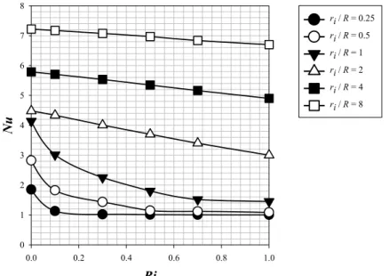
The variations of the mean Nusselt number 𝑁𝑢̅̅̅̅ with Richardson number 𝑅𝑖 are presented in Figure 4 for different 𝑟𝑖/𝑅 values at 𝑅𝑒 = 1000 and 𝑃𝑟 = 1. Figure 4 shows that 𝑁𝑢̅̅̅̅ monotonically decreases with increasing 𝑅𝑖
which is consistent with the scaling estimation given by Eq. (18). This can be explained in the following manner. For mixed convection (i.e. 𝑅𝑖 > 0), the relative strengths of inertial, buoyancy and viscous forces determine the flow behaviour. For 𝑅𝑖 = 0, which corresponds to purely forced convection, the flow is governed by the inertial and viscous forces. The influence of buoyancy force starts to strengthen with increasing 𝑅𝑖, and therefore the competition between buoyancy and viscous forces becomes increasingly important with increasing 𝑅𝑖. However, this configuration, where the top cover is hotter than the bottom one, represents a stable condition where the lighter hot fluid sits on top of heavier cold fluid so the effects of natural convection remain significant only close to the heated top cover and thus the net advective transport weakens and the mean Nusselt number decreases with increasing Ri. In addition, it is also observed from Figure 4 that the influence of Richardson number on the mean Nusselt number weakens with increasing 𝑟𝑖/𝑅 and a decreasing in the mean Nusselt number with increasing Ri remains relatively limited levels in the case of
high 𝑟𝑖/𝑅 values. This is also expected from the scaling estimation given by Eq. (18). Eq. (18) explicitly indicates that
the ratio of 𝑅𝑖 /(1 + 𝑟𝑖/𝑅) decreases with increasing 𝑟𝑖/𝑅. As a results of this, the influence of Richardson number
on the mean Nusselt number decreases with increasing 𝑟𝑖/𝑅. The observations made from Figure 4 can further be
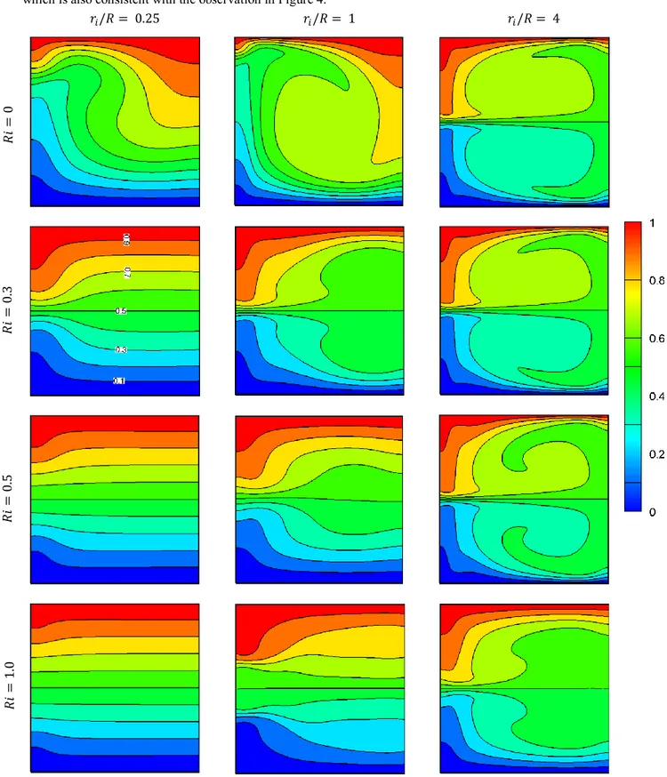
explained from the non-dimensional temperature countors 𝜃, which are presented in Figure 3 for different 𝑅𝑖 values at 𝑅𝑒 = 1000 and 𝑃𝑟 = 1. It can be observed from Figure 3 that isotherms become increasingly parallel to the horizontal walls with increasing Ri in the case of small 𝑟𝑖/𝑅 (i.e. 𝑟𝑖/𝑅 = 0.25). This indicates that convection weakens with
increasing Ri and thermal transport takes place predominantly due to conduction for large values of Ri. This leads to a decrease in the mean Nusselt number with increasing Ri as observed in Figure 4. On the other hand, it is also observed
7
from Figure 3 that the influence of Richardson number on the isotherm weakens with increasing 𝑟𝑖/𝑅 (i.e. 𝑟𝑖/𝑅 = 4)
which is also consistent with the observation in Figure 4.
𝑟𝑖/𝑅 = 0.25 𝑟𝑖/𝑅 = 1 𝑟𝑖/𝑅 = 4
Figure 3. Contours of non-dimensional temperature 𝜃 for different values of 𝑅𝑖 and 𝑟𝑖/𝑅 at 𝑅𝑒 = 1000 and 𝑃𝑟 = 1
𝑅𝑖 = 0 𝑅𝑖 = 0 .3 𝑅𝑖 = 0 .5 𝑅𝑖 = 1 .0
Journal of Thermal Engineering, Research Article, Vol. 6, No. 1, pp. 1-15, January, 2020
8
Figure 4. Variation of 𝑁𝑢̅̅̅̅ with 𝑅𝑖 for different 𝑟𝑖/𝑅 values at 𝑅𝑒 = 1000 and 𝑃𝑟 = 1 Influences of 𝒓𝒊/𝑹
The variation of the mean Nusselt number 𝑁𝑢̅̅̅̅ with 𝑟𝑖/𝑅 for low (i.e. 𝑅𝑖 = 0.1) and high (i.e. 𝑅𝑖 = 1.0)
Richardson number cases at 𝑅𝑒 = 1000 and Pr = 1 are shown in Figure 5. It can be seen from Figure 5 that 𝑁𝑢̅̅̅̅ increases with increasing 𝑟𝑖/𝑅 for both low and high Ri values. This is consistent with the scaling estimate of the mean
Nusselt number given by Eq. (18) which also suggests that 𝑁𝑢̅̅̅̅ is expected to increase with increasing 𝑟𝑖/𝑅. An increase
in Nusselt number with increasing 𝑟𝑖/𝑅 bears the signature of strengthening of advective transport. This can be
substantiated from Figure 6, in which the distributions of non-dimensional swirl velocity component 𝑉𝜙 (= 𝑣𝐻/𝛼 )
along the vertical mid-plane ((𝑟𝑜− 𝑟𝑖)/𝑅 = 0.5) are shown for 𝑅𝑖 = 0.1 and 1.0 at 𝑅𝑒 = 1000 at Pr = 1. Figure 6
demonstrates that the magnitude of 𝑉𝜙 increases with increasing 𝑟𝑖/𝑅 values, which is an evident of strengthening of
advective transport in the flow field. This also leads to an increase in the mean Nusselt number observed in Figure 5.
Figure 5. Variation of mean Nusselt number 𝑁𝑢̅̅̅̅ with 𝑟𝑖/𝑅 for 𝑅𝑖 = 0.1 and 1.0 at 𝑅𝑒 = 1000 and 𝑃𝑟 = 1
Ri 0.0 0.2 0.4 0.6 0.8 1.0 Nu 0 1 2 3 4 5 6 7 8 ri / R = 0.25 ri / R = 0.5 ri / R = 1 ri / R = 2 ri / R = 4 ri / R = 8
Ri
0.0 0.2 0.4 0.6 0.8 1.0Nu
0 1 2 3 4 5 6 7 8 ri / R = 0.25 ri / R = 0.5 ri / R = 1 ri / R = 2 ri / R = 4 ri / R = 8r
i/ R
0.1 1 10Nu
0 1 2 3 4 5 6 7 8 ri / R = 0.1 ri / R = 1.0
9
The strengthening of advective transport with increasing 𝑟𝑖/𝑅, which is observed in Figs. 5 and 6, could
alternatively be explained by integrating convective heat transport through the boundary layer thickness on the bottom cover: 𝑄𝑐𝑜𝑛𝑣= 𝑄𝑎𝑑𝑣+ 𝑄𝑑𝑖𝑓𝑓= ∫ 𝜌𝑐𝑝𝑢∆𝑇𝑑𝑧 𝛿 0 − ∫ 𝑘(𝜕𝑇/𝜕𝑟)𝑑𝑧 𝛿 0 (19) where 𝑄𝑎𝑑𝑣= ∫ 𝜌𝑐𝑝𝑢∆𝑇𝑑𝑧 𝛿 0 ~𝜌𝑐𝑝𝑈∆𝑇𝛿 (20a) 𝑄𝑑𝑖𝑓𝑓= − ∫ 𝑘 ( 𝜕𝑇 𝜕𝑟) 𝑑𝑧 𝛿 0 ~(𝑘∆𝑇)𝛿 𝑅 (20b)
where 𝛿 is the hydro-dynamic boundary layer thickneess on the horizontal walls. Substituting 𝑈~𝑎[𝛺𝑅(1 + 𝑟𝑖/𝑅)] +
𝑏[√𝑔𝛽𝛥𝑇𝑅(1 + 𝑟𝑖/𝑅)] and the scaling relation for 𝛿 from Eq. (16) into Eqs. (20a) and (20b) yield the following
scaling estimates for the magnitudes of 𝑄𝑎𝑑𝑣 and 𝑄𝑑𝑖𝑓𝑓:
𝑄𝑎𝑑𝑣~(𝑘 ∆𝑇) 𝑃𝑟 𝑅𝑒1/2(1 + 𝑟𝑖/𝑅)1/2[𝑎 + 𝑏 ( 𝑅𝑖 1 + 𝑟𝑖/𝑅 ) 1/2 ] 3/2 (21a) 𝑄𝑑𝑖𝑓𝑓~(𝑘 ∆𝑇) 𝑅𝑒−1/2(1 + 𝑟𝑖/𝑅)−1/2[𝑎 + 𝑏 ( 𝑅𝑖 1 + 𝑟𝑖/𝑅 ) 1/2 ] 1/2 (21b)
Eqs. (21a) and (21b) indicate that the advective heat transport 𝑄𝑎𝑑𝑣 strengthens with increasing 𝑟𝑖/𝑅 whereas
diffusive heat transport 𝑄𝑑𝑖𝑓𝑓 weakens with increasing 𝑟𝑖/𝑅. For this reason, the mean Nusselt number 𝑁𝑢̅̅̅̅ and
non-dimensional swirl velocity component 𝑉𝜙 show an inceare with increasing 𝑟𝑖/𝑅, as shown in Figs. 5 and 6.
(a) (b)
Figure 6. The distributions of non-dimensional swirl velocity component 𝑉𝜙 (= 𝑣𝐻/𝛼 ) along the vertical
mid-plane ((𝑟𝑜− 𝑟𝑖)/𝑅 = 0.5) for different 𝑟𝑖/𝑅 values for (a) 𝑅𝑖 = 0.1 and (b) 1.0 at 𝑅𝑒 = 1000 at Pr = 1 z / H 0.0 0.2 0.4 0.6 0.8 1.0 V 0 200 400 600 800 1000 1200 1400 ri / R = 0.25 ri / R = 1.00 ri / R = 4.00 Ri = 0.1 z / H 0.0 0.2 0.4 0.6 0.8 1.0 V 0 200 400 600 800 1000 1200 1400 1600 r i / R = 0.25 r i / R = 1.00 ri / R = 4.00 Ri = 1.0
Journal of Thermal Engineering, Research Article, Vol. 6, No. 1, pp. 1-15, January, 2020
10
Influences of 𝑹𝒆
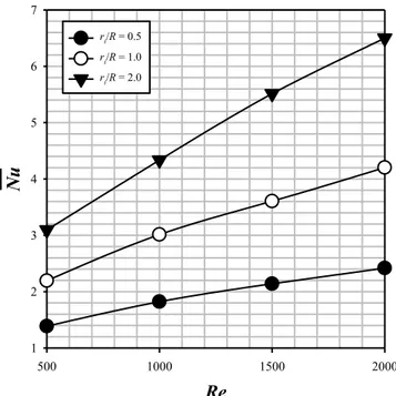
The variation of the mean Nusselt number 𝑁𝑢̅̅̅̅ with Reynolds number 𝑅𝑒 for different 𝑟𝑖/𝑅 values at
𝑅𝑖 = 0.1 (i.e. a representative mixed convection case) and Pr = 1 are shown in Figure 7. It can be seen from Figure 7 that 𝑁𝑢̅̅̅̅ increases with increasing Re for all 𝑟𝑖/𝑅 case. This is consistent with the scaling estimate of the mean Nusselt
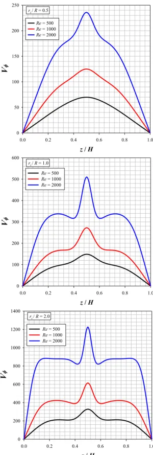
number given by Eq. (18) which also suggests that 𝑁𝑢̅̅̅̅ is expected to increase with increasing 𝑅𝑒. In addition to this, the distributions of non-dimensional swirl velocity component 𝑉𝜙 (= 𝑣𝐻/𝛼 ) along the vertical mid-plane (𝑟/𝑅 = 0.5)
are shown in Figure 8 for different values 𝑟𝑖/𝑅 at 𝑅𝑖 = 0.1 (i.e. a representative mixed convection case) at Pr = 1. It
can be seen from Figure 8 that the magnitude of 𝑉𝜙 increases with increasing 𝑅𝑒 for all 𝑟𝑖/𝑅 cases. This indicate a
strengthening of advective transport with increasing Reynolds number, which leads to an increase in heat transfer rate in the enclosure as observed in Figure 7. This can also be explained by Eq. (21a) which indicates that the convective heat transport 𝑄𝑐𝑜𝑛𝑣 strengthens with increasing 𝑅𝑒 as observed in Figs. 7 and 8. For this reason, the mean Nusselt
number 𝑁𝑢̅̅̅̅ increaes with increasing 𝑅𝑒 for all 𝑟𝑖/𝑅 cases (Figure 7).
Figure 7. Variation of mean Nusselt number 𝑁𝑢̅̅̅̅ with Reynolds number 𝑅𝑒 for different 𝑟𝑖/𝑅 values at 𝑅𝑖 = 0.1 and
𝑃𝑟 = 1
Flow regimes
The variation of non-dimensional stream functions Ψ = 𝜓/𝛼 are shown in Figure 9 for different 𝑅𝑖 and 𝑟𝑖/𝑅
values at 𝑅𝑒 = 1000 and 𝑃𝑟 = 1. It is apparent from Figure 9 that the flow pattern in the case of purely forced convection (i.e. 𝑅𝑖 = 0) is significantly different from those in mixed convection. In the case of 𝑅𝑖 = 0 (i.e. purely forced convection), a one-cell flow structure with two small vortexes on the top corners is observed for 𝑟𝑖/𝑅 ≤ 1,
whereas a second cell appears in the flow field for 𝑟𝑖/𝑅 > 1 at 𝑅𝑒 = 1000. On the other hand, in the case of mixed
convection (i.e. 𝑅𝑖 > 0), two-cell and four-cell flow structures occur in the flow field depending on 𝑅𝑖, and 𝑟𝑖/𝑅 for
the range of 𝑅𝑖 and 𝑟𝑖/𝑅 considered here at 𝑅𝑒 = 1000. It is also worth noting that similar behaviour has also been
observed for different Reynolds number values (i.e. Re = 500 and 2000). Based these observations, a flow regime diagram has been proposed here for mixed convection (i.e. 𝑅𝑖 > 0) for the range of 𝑅𝑖 and 𝑟𝑖/𝑅 analysed in this study.
According to this diagram, the flow patterns in the mixed convection for this configuration are classified into two
different zones in terms of Richardson number 𝑅𝑖 and 𝑟𝑖/𝑅 as shown in Figure 10. The region, where
𝑅𝑖 + 1 ≤ 1.75 (𝑟𝑖/𝑅)0.22 (𝑅𝑖 + 1 ≤ 1.50 (𝑟𝑖/𝑅)0.22) for 𝑅𝑒 ≤ 1000 (𝑅𝑒 > 1000) is termed as the Regime 1, which
exhibits two-cell flow pattern. The Regime 2 is characterised by 𝑅𝑖 + 1 > 1.75 (𝑟𝑖/𝑅)0.22 (𝑅𝑖 + 1 > 1.50 (𝑟𝑖/𝑅)0.22)
for 𝑅𝑒 ≤ 1000 (𝑅𝑒 > 1000) where a four-cell flow pattern occurs. It needs to be highlighted that the boundaries which distinguish one regime from another in Figure 10 are based on the observations made from simulation results. As such these boundaries should not be treated rigidly but need to be considered only in an order of magnitude sense.
Re
500 1000 1500 2000Nu
1 2 3 4 5 6 7 ri/R = 0.5 ri/R = 1.0 ri/R = 2.0
11
Figure 8. The distributions of non-dimensional swirl velocity component 𝑉𝜙 (= 𝑣𝐻/𝛼 ) along the vertical mid-plane
((𝑟𝑜− 𝑟𝑖)/𝑅 = 0.5) for different 𝑅𝑒 values for 𝑟𝑖/𝑅 = 0.5, 1.0 and 2.0 at 𝑅𝑖 = 0.1 and 𝑃𝑟 = 1 z / H 0.0 0.2 0.4 0.6 0.8 1.0 V 0 50 100 150 200 250 Re = 500 Re = 1000 Re = 2000 ri / R = 0.5 z / H 0.0 0.2 0.4 0.6 0.8 1.0 V 0 100 200 300 400 500 600 Re = 500 Re = 1000 Re = 2000 ri / R = 1.0 z / H 0.0 0.2 0.4 0.6 0.8 1.0 V 0 200 400 600 800 1000 1200 1400 Re = 500 Re = 1000 Re = 2000 ri / R = 2.0
Journal of Thermal Engineering, Research Article, Vol. 6, No. 1, pp. 1-15, January, 2020 12 𝑅𝑖 = 0 𝑅𝑖 = 0.1 𝑅𝑖 = 0.3 𝑅𝑖 = 0.5 𝑅𝑖 = 0.7 𝑅𝑖 = 1 𝑟𝑖 /𝑅 = 0 .25 𝑟𝑖 /𝑅 = 0 .5 𝑟𝑖 / 𝑅 = 1 𝑟𝑖 /𝑅 = 2 𝑟𝑖 /𝑅 = 4
Figure 9. Contours of non-dimensional stream functions (i.e. Ψ = 𝜓/𝛼) for different values of 𝑅𝑖 and 𝑟𝑖/𝑅 at
𝑅𝑒 = 1000 and 𝑃𝑟 = 1
Figure 10. Flow regime diagram on 𝑟𝑖/𝑅 – 𝑅𝑖 plane for mixed convection (i.e. 𝑅𝑖 > 0) for the considered
configuration in this study for 500 ≤ 𝑅𝑒 ≤ 2000 and 𝑃𝑟 = 1 ri / R 0.0 0.5 1.0 1.5 2.0 Ri 0.0 0.2 0.4 0.6 0.8 1.0 Regime 1 Regime 2 𝑹𝒊 = 𝟏. 𝟕𝟓(𝒓𝒊/𝑹)𝟎.𝟐𝟐− 𝟏 𝑹𝒊 = 𝟏. 𝟓𝟎(𝒓𝒊/𝑹)𝟎.𝟐𝟐− 𝟏 for 𝑅𝑒 ≤ 1000 for 𝑅𝑒 > 1000
13
CONCLUSION
The effects of Ri and 𝑟𝑖/𝑅 on heat and momentum transport in steady state laminar mixed convection in a
square cross-sectioned cylindrical annular enclosure with a rotating inner wall and heated from top cover have been numerically analysed based on axisymmetric incompressible flow condition at 𝑃𝑟 = 1. It has been found out that 𝑁𝑢̅̅̅̅ demonstrates a monotonically decreasing trend with increasing 𝑅𝑖 for the range of 𝑟𝑖/𝑅 and 𝑅𝑒 considered here. It has
been also found that advective transport in the flow field strengthens with increasing 𝑟𝑖/𝑅 and 𝑅𝑒. This leads to an
increase in the mean Nusselt number with increasing 𝑟𝑖/𝑅 and 𝑅𝑒 which is consistent with the scaling estimation of
the mean Nusselt number. In addition, it has been observed that flow pattern in the case of purely forced convection (i.e. 𝑅𝑖 = 0) is significantly different from those in mixed convection (i.e. 𝑅𝑖 = 0). In the case of 𝑅𝑖 = 0 (i.e. purely forced convection), a one-cell flow structure with two small vortexes on the top corners is observed for 𝑟𝑖/𝑅 ≤ 1,
whereas a second cell appears in the flow field for 𝑟𝑖/𝑅 > 1. On the other hand, in the case of mixed convection (i.e.
𝑅𝑖 > 0), two-cell and four-cell flow structures occur in the flow field depending on 𝑅𝑖, 𝑅𝑒 and 𝑟𝑖/𝑅 for the range of
𝑅𝑖, 𝑅𝑒 and 𝑟𝑖/𝑅 considered here at 𝑃𝑟 = 1.0. Based these observations, a flow regime diagram has been proposed
here for mixed convection (i.e. 𝑅𝑖 > 0) for the range of 𝑅𝑖 and 𝑟𝑖/𝑅 analysed in this study. NOMENCLATURE
a Bridging function AR Aspect ratio, (AR = H/R) b Bridging function
cp Specific heat at constant pressure, J/kgK
ea Relative error
f1 General Function
g Gravitational acceleration, m/s2 Gr Grashof number
h Heat transfer coefficient, W/m2K H Height of cylindrical enclosure, m k Thermal conductivity, W/mK Nu Nusselt number
𝑁𝑢
̅̅̅̅ Mean Nusselt number Pr Prandtl number q Heat flux, W/m2 𝑄 Heat transfer rate, W ri Inner radius, m
ro Outer radius, m
R Radius of cylindrical enclosure, m Ra Rayleigh number
Re Reynolds number
Ri Richardson number
T Temperature, K
U Characteristic velocity scales in radial direction, m/s V Characteristic velocity scales in tangential direction, m/s 𝑉𝜙 Non-dimensional swirl velocity, (𝑉𝜙= 𝑣𝐻/𝛼)
α Thermal diffusivity, m2/s
β Coefficient of thermal expansion, 1/K 𝛾̇ Shear rate, 1/s
δ,δth Hydrodynamic and thermal boundary layer thickness, m
θ Non- dimensional temperature, ( θ = (T-TC )/( TH-TC )) μ Plastic viscosity, Ns/m2
Journal of Thermal Engineering, Research Article, Vol. 6, No. 1, pp. 1-15, January, 2020 14 𝜈 Kinematic viscosity, m2/s ρ Density, kg/m3 𝜏 Shear stress, N/m2 Ω Angular velocity, 1/s 𝜓 Stream function, m2/s
Ψ Non-dimensional stream function, (Ψ = 𝜓/𝛼)
Subscripts adv Advective C Cold wall conv Convective diff Diffusive H Hot wall r Radial direction ref wall Reference value Wall value
wf Condition of the fluid in contact with the wall z Axial direction
𝜙 Tangential direction
Special characters
∆𝑇 Difference between hot and cold wall temperature ( = ( TH-TC )), K ∆𝑚𝑖𝑛,𝑐𝑒𝑙𝑙
cell , min
Minimum cell distance, m r Grid expansion ratio
REFERENCES
[1] Zandbergen PJ, Dikstra D. Von Karman swirling flows. Annual Reviews Fluid Mechanics 1987;19:465-491. https://doi.org/10.1146/annurev.fl.19.010187.002341
[2] Vogel HU, Experimentelle Ergebnisse über die laminare Strömung in einem zylindrischen Gahause mit darin rotieren-der Scheibe. MPI Bericht 6; 1968.
[3] Vogel HU, Rückströmungsblasen in Drallsströmungen. Festschrift 50 Jahre Max-Planck-Institut für Strömungsforschung 1925-1975, 1975.
[4] Ronnenberg B. Ein selbstjustierendes 3-Komponenten-Laserdoppleranemometer nach dem Vergleichsstrahlverfahren, angewandt für Untersuchungen in einer stationaren sylinder-symmetrischen Drehströmung mit einem Rückstromgebiet. MPI Bericht 20, 1977.
[5] Bertela M, Gori F. Laminer flow in a cylindrical container with a rotating cover. Journal of Fluids Engineering 1982;104:31-39. https://doi.org/10.1115/1.3240849.
[6] Escudier MP. Observations of the flow produced in a cylindrical container by rotating endwall. Experiments in Fluids 1984;2:189-196. https://doi.org/10.1007/BF00571864.
[7] Lugt HJ, Haussling HJ. Axisymmetric vortex breakdown in rotating fluid within a container. Journal of Applied Mechanics 1982;49:921-923. https://doi.org/10.1115/1.3162645.
[8] Lopez JM. Axisymmetric vortex breakdown: Part1. Confined swirling flow. Journal Fluid Mechanics 1990;221: 533-552. https://doi.org/10.1017/S0022112090003664.
[9] Kim WN, Hyun JM. Convective heat transfer in a cylinder with a rotating lid under stable stratification. Int J of Heat and Fluid Flow 1997;18:384-388. https://doi.org/10.1016/S0142-727X(97)00012-X.
[10] Lee CH, Hyun JM. Flow of a stratified fluid in a cylinder with a rotating lid. Int J of Heat and Fluid Flow 1999;20: 26-33. https://doi.org/10.1016/S0142-727X(98)10041-3.
[11] Iwatsu R. Flow pattern and heat transfer of swirling flows in cylindrical container with rotating top and stable temperature gradient. International Journal of Heat and Mass Transfer 2004; 47: 2755-2767. https://doi.org/10.1016/j.ijheatmasstransfer.2003.11.032.
[12] Escuider MP, O’Leary J, Poole RJ. Flow produced in a conical container by a rotating end wall. Int J of Heat and Fluid Flow 2007;28:1418-1428. https://doi.org/10.1016/j.ijheatfluidflow.2007.04.018.
15
[13] Turan O, Yigit S, Chakraborty N. Effects of wall heating on laminar mixed convection in a cylindrical enclosure with a rotating end wall. Journal of Thermal Science 2018;131:80-93. https://doi.org/10.1016/j.ijthermalsci.2018.05.005
![Figure 2. Comparison of present simulation results with benchmark results by Iwatsu [11] SCALING ANALYSIS](https://thumb-eu.123doks.com/thumbv2/9libnet/4034518.56469/5.918.301.619.107.412/figure-comparison-present-simulation-results-benchmark-scaling-analysis.webp)