AN AXISYMMETRIC CONTACT PROBLEM FOR A BI-LAYERED TRANSVERSELY ISOTROPIC SLAB RESTING ON A RIGID CIRCULAR SUPPORT
M. İlker BAY1, Behcet DAĞHAN2, Mesut UYANER3
1Devlet Su İşleri Genel Müdürlüğü Makina, Etlik Cad. No:47 06110 Etlik/ANKARA, Turkey 2Selçuk University, Faculty of Engineering, Mechanical Engineering Department, Konya, Turkey 3Selçuk University, Faculty of Engineering, Metallurgical and Materials Engineering Dept., Konya, Turkey
1[email protected], 2[email protected], 3[email protected]
ABSTRACT: This paper is concerned with the continuous contact problem of two transversely isotropic
layers resting on a circular support. The external load is applied to the layers by a rigid cylindrical block. It is assumed that the contact between all surfaces is frictionless and body forces are not taken into account. The problem is formulated in terms of singular integral equations obtained from the continuous contact position. Equations are solved numerically by using the Gauss-Chebyshev integration method. Furthermore, numerical results as pressure distributions under the rigid cylindrical block are given for different material combinations.
Keywords: Contact problem, Transversely isotropic material, Rigid cylindrical block, Circular support, Singular integral equation.
Rijit Çembersel Destek Üzerinde Duran İki Katmanlı Enine-İzotrop Slabın Eksenel Simetrik Temas Problemi
ÖZET: Bu makale, çembersel destek üzerinde duran iki adet enine-izotrop katmanın sürekli temas
problemini ele almaktadır. Dış yük, katmanlara bir rijit silindirik blok vasıtasıyla tatbik edilmiştir. Tüm yüzeylerin arasındaki temasın sürtünmesiz olduğu kabul edilmiş ve kütle kuvvetleri hesaba katılmamıştır. Problem, sürekli temas konumundan elde edilen tekil integral denklemler cinsinden formüle edilmiştir. Denklemler Gauss-Chebyshev integrasyon yöntemi ile nümerik olarak çözülmüştür. Bunun dışında, rijit silindirik blok altındaki basınç dağılımlarına ait sayısal sonuçlar birçok farklı malzeme kombinasyonları için verilmiştir.
Anahtar Kelimeler: Temas problemi, Enine-izotrop malzeme, Rijit silindirik blok, Çembersel destek, Tekil integral denklemi.
1. INTRODUCTION
In recent years, there is an increasing interest on anisotropic materials due to high strength over density ratio and tailor fit strength properties. Also, the elastic properties of the materials become different due to certain technological processes such as rolling and the condition of anisotropy must be considered. Metallic substances, such as zinc and magnesium are characterised as being transversely isotropic and have five elastic constants. Many
fiber-reinforced composite materials are also characterised as transversely isotropic media.
Adams and Zeid, 1984 have investigated an elastic punch moving across the surface of a semi-infinite solid. Bakırtaş, 1980 studied a rigid punch problem in a non-homogeneous elastic half-space. The axially symmetric double contact problem for frictionless elastic layer studied by Civelek and Erdoğan, 1974. Civelek, 1972 introduced the axi-symmetric contact problem for an elastic layer on a frictionless half-space. Uyaner et al., 2000 have investigated plastic zones in a transversely
isotropic cylinder containing a ring shaped crack. Fabrikant and Sankar, 1986 introduced concentrated force underneath a punch bonded to a transversely isotropic half-space. The non-symmetrical plane elasticity problem of an elastic layer supported by two elastic quarter plane solved by Aksoğan et al., 1997. The frictionless contact problem between an infinite layer bonded to a rigid support and a rigid stamp considered by Kahya et al., 2001 . Punch problem for an elastic layer overlying an elastic foundation analyzed by Dhaliwal, 1970. Frictionless contact problem for an elastic layer under axisymmetric loading were studied by Geçit and Erdoğan, 1978. Ratwani and Erdoğan, 1973 have investigated on the plane contact problem for a frictionless elastic layer. Geçit, 1986 introduced the axisymmetric double contact problem for a frictionless elastic layer indented by an elastic layer. Avci et al., 2006a studied an axisymmetric smooth contact for an elastic isotropic infinite hollow cylinder compressed by an outer rigid ring with circular profile. Uyaner et al., 2002 considered a problem in an elastic-perfectly plastic dissimilar layered medium. They assumed that a transversely isotropic layer is sandwiched between two isotropic semi-infinite half spaces, and contains a penny-shaped crack located in its mid-plane. A contact problem for a transversely isotropic cylinder radially compressed by a rigid toroidal indenter was considered by Avci et al., 2006b.
In this study, the plane elastostatic problem of transversely isotropic layers resting on a circular support under effect of pressure load by means of a rigid cylindrical block is considered. The general equation of stresses and displacements are obtained by using the general equation of elasticity and Hankel transform among integral transform techniques. The continuous contact problem is considered. A set of linear algebraic equation is obtained by applying the expression of stresses and displacements to secondary conditions of the continuous contact problem. When the set of linear algebraic equation is solved, the unknown constant coefficients using the equation of stresses and displacements are obtained. The singular integral equations are numerically solved by using the Gauss-Chebyshev integration method. The diagrams of pressure distributions under the rigid cylindrical block are plotted.
2. BASIC FORMULATION
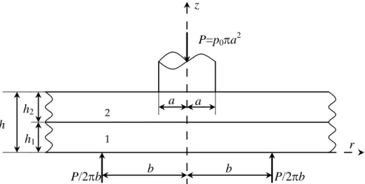
Consider two infinite transversely isotropic layers of thickness h, shown in Fig. 1. The external uniform compression load P is applied to the transversely isotropic layers through a frictionless semi-infinite cylinder of diameter 2a. The body forces are neglected. It is assumed that the contact between the layers is frictionless and the interface transmits only compressive stresses.
Figure 1. Geometry of the problem
Referring to Fig. 1, the equilibrium and the compatibility equations are expressed in cylindrical coordinates as
P=p
0πa
2P/2
πb
b
b
P/2
πb
a
a
h
h
2h
1z
r
1 20
=
−
+
∂
∂
+
∂
∂
r
z
r
r rz rτ
σ
σ
θσ
(1a)0
=
+
∂
∂
+
∂
∂
r
z
r
rz z rzσ
τ
τ
(1b) For transversely isotropic bodies the stress components can be written as (Lekhnitskii, 1981) z r rc
ε
c
ε
c
ε
σ
=
11+
12 θ+
13 (2a) z rc
c
c
ε
ε
ε
σ
θ=
12+
11 θ+
13 (2b) z r zc
ε
ε
c
ε
σ
=
13(
+
θ)
+
33 (2c) rz rzc
γ
τ
=
44 (2d) wherer
u
r∂
∂
=
ε
(3a)r
u
=
θε
(3b)z
w
z∂
∂
=
ε
(3c)r
w
z
u
rz∂
∂
+
∂
∂
=
γ
, (3d)The stress components may be expressed in terms of displacements u(r,z) and w(r,z) as,
z
w
c
r
u
c
r
u
c
r∂
∂
+
+
∂
∂
=
11 12 13σ
(4a)z
w
c
r
u
c
r
u
c
∂
∂
+
+
∂
∂
=
12 11 13 θσ
(4b)z
w
c
r
u
r
u
c
z∂
∂
+
+
∂
∂
=
13 33σ
(4c)
∂
∂
+
∂
∂
=
r
w
z
u
c
rz 44τ
(4d)where cij (i,j=1..4) are elastic constants. Substituting equations (4a), (4b), (4c), and (4d) into the equations (1a) and (1b) the following two partial differential equations are obtained.
(
)
0
1
2 44 13 2 2 44 2 2 2 11=
∂
∂
∂
+
+
∂
∂
+
−
∂
∂
+
∂
∂
r
z
w
c
c
z
u
c
r
u
r
u
r
r
u
c
(5)0
1
1
)
(
2 2 33 2 2 44 2 44 13=
∂
∂
+
∂
∂
+
∂
∂
+
∂
∂
+
∂
∂
∂
+
z
w
c
r
w
r
r
w
c
z
u
r
r
z
u
c
c
(6)In order to solve these differential equations Hankel transform pairs can be used as
ξ
ξ
ξ
ξ
z
J
r
d
z
r
u
(
,
)
(
,
)
1(
)
0Φ
=
∫
∞ (7a)dr
r
J
z
r
u
r
z
)
(
,
)
(
)
,
(
1 0ξ
ξ
=
∞∫
Φ
(7b)ξ
ξ
ξ
ξ
z
J
r
d
z
r
w
(
,
)
(
,
)
0(
)
0Ψ
=
∞∫
(8a)dr
r
J
z
r
w
r
z
)
(
,
)
(
)
,
(
0 0ξ
ξ
=
∞∫
Ψ
(8b)For a transversely isotropic layer, it is necessary to select the displacements functions
) , ( zr
u and w( zr, ) of the forms
∫
∞+
+
+
=
0 1(
)
)
(
)
,
(
r
z
ξ
A
e
1ξB
e
2ξC
e
3ξD
e
4ξJ
ξ
r
d
ξ
u
i i m z i m z i m z i m z (i=1,2) (9)∫
∞
−
+
−
+
−
+
−
=
0 0 4 3 4 3 3 3 2 3 2 1 3 1)
(
)
(
)
(
)
(
)
(
)
,
(
4 3 2 1ξ
ξ
ξ
ξ ξ ξ ξJ
r
d
e
D
d
m
fm
e
C
d
m
fm
e
B
d
m
fm
e
A
d
m
fm
z
r
w
z m i z m i z m i z m i i (i=1,2) (10)where
A
i,
B
i,
C
i,
D
i (i=1,2) are unknownfunctions which are determined from the boundary conditions and m1, m2, m3, m4, d, f as
2
4
2 3 , 1b
a
a
m
=
±
−
(11a)2 4 2 4 , 2 b a a m =− ± − (11b) ) ( ) ( 44 13 44 2 44 13 33 11 c c c c c c c d + + − = (12a) 44 13 33 c c c f + = (12b)
where J0(ξr) and J1(ξr)are Bessel functions
of first kind. Stresses and strains can be written after substituting u( zr, ) and w( zr, ) into the equations (4a), (4b), (4c), and (4d) as
ξ ξ ξ ξ ξ ξ σ ξ ξ ξ ξ ξ ξ ξ ξ d r J e D d m fm c c e C d m fm c c e B d m fm c c e A d m fm c c d r J e D e C e B e A r c c z r z m i z m i z m i z m i z m i z m i z m i z m i ir ) ( )) ( ( )) ( ( )) ( ( )) ( ( ) ( ) ( ) , ( 0 0 2 4 4 4 13 11 2 3 4 3 13 11 2 2 4 2 13 11 2 1 4 1 13 11 2 0 1 11 12 4 3 2 1 4 3 2 1
∫
∫
∞ ∞ − + + − + + − + + − + + + + + − = (13a) ξ ξ ξ ξ ξ ξ σ ξ ξ ξ ξ ξ ξ ξ ξ θ d r J e D d m fm c c e C d m fm c c e B d m fm c c e A d m fm c c d r J e D e C e B e A r c c z r z m i z m i z m i z m i z m i z m i z m i z m i i ) ( )) ( ( )) ( ( )) ( ( )) ( ( ) ( ) ( ) , ( 0 0 2 4 4 4 13 12 2 3 4 3 13 12 2 2 4 2 13 12 2 1 4 1 13 12 2 0 1 12 11 4 3 2 1 4 3 2 1∫
∫
∞ ∞ − + + − + + − + + − + + + + + − = (13b) ξ ξ ξ σ ξ ξ ξ ξ d r J e D d m fm c c e C d m fm c c e B d m fm c c e A d m fm c c z r z m i z m i z m i z m i iz ( ) )) ( ( )) ( ( )) ( ( )) ( ( ) , ( 0 0 2 4 4 4 33 13 2 3 4 3 33 13 2 2 4 2 33 13 2 1 4 1 33 13 2 4 3 2 1∫
∞ − + + − + + − + + − + = (13c) ξ ξ ξ τ ξ ξ ξ ξ d r J e D d m fm m c e C d m fm m c e B d m fm m c e A d m fm m c z r z m i z m i z m i z m i irz ( ) )) ( ( )) ( ( )) ( ( )) ( ( ) , ( 1 0 4 3 4 4 44 3 3 3 3 44 2 3 2 2 44 1 3 1 1 44 2 4 3 2 1∫
∞ − − + − − + − − + − − = (13d)3. SOLUTION OF THE PROBLEM
Assuming that the contacts between all surfaces are frictionless, the boundary conditions may be expressed as 0 ) , ( 1rz r z = τ
z
=
0
(14a) 0 ) , ( 1rz r z = τ z=h1 (14b) 0 ) , ( 2rz r z = τz
=
h
1 (14c) 0 ) , ( 2rz r z = τz
=
h
(14d)[
1( , )− 2( , )]
=0 ∂ ∂ z r w z r w r z=h1 (14e) ) , ( ) , ( 2 1z r z σ z r z σ = z=h1 (14f) ) ( 2 ) , ( 1 r b b P z r z =− π δ − σ , ≠ = = − b r b r b r 0 1 ) ( δ z=0 (14g) ) ( ) , ( 2z r z =−p r σ ,−a<r<a,z
=
h
(14h) 0 ) , ( 2 r h = w −∞<r<−a (14i) 0 ) , ( 2 r h = w a< r<∞ (14j)In equations (14a,…,14h) the continuity conditions for the displacements are expressed in terms of derivatives for dimensional consistency in the equations of the problem. From equilibrium condition,
∫
=− =− a z r hdr P p a r 0 2 0 2 ( , ) 2π σ π (14k)By substituting (13d) into (14a), 0 1 14 1 13 1 12 1 11A +x B +x C +x D = x (15) where )) ( ( 3 1 m fm md xi= i− i − i i=1..4 (15a)
By substituting (13d) into (14b), we get 0 1 24 1 23 1 22 1 21A +x B +x C +x D = x (16) where 1 )) ( ( 3 2 h m i i i i m fm md e i x = − − ξ i=1..4 (16a)
Substituting (13d) into (14c), the following equation can be obtained
0
2 24 2 23 2 22 2 21A
+
x
B
+
x
C
+
x
D
=
x
(17) where 1))
(
(
3 2 h m i i i i ie
d
m
fm
m
x
=
−
−
ξ i=1..4 (17a) By substituting (13d) into (14d), 0 2 34 2 33 2 32 2 31A +x B +x C +x D = x (18) h m i i i i m fm md e i x3 =( −( 3− )) ξ i=1..4 (18a)By substituting (10) into (14e), we get
0 2 44 2 43 2 42 2 41 1 44 1 43 1 42 1 41 = − − − − + + + D x C x B x A x D x C x B x A x (19) 1 ) ( 3 4 h m i i i fm md e i x = − ξ i=1..4 (19a) By substituting (13c) into (14f), 0 2 54 2 53 2 52 2 51 1 54 1 53 1 52 1 51 = − − − − + + + D x C x B x A x D x C x B x A x (20) 1 )) ( ( 13 33 4 2 5 h m i i i c c fm m d e i x = + − ξ i=1..4 (20a)
Finally, by substituting (13c) into (14g),
n D x C x B x A x D x C x B x A x = − − − − + + + 2 64 2 63 2 62 2 61 1 64 1 63 1 62 1 61 (21) )) ( (13 33 4 2 6 c c fm m d xi= + i − i i=1..4 (21a)
∫
∞ − − = 0 0( ) ) ( 2 b r r b J r dr P n δ ξ π (r=b) (21b)By using derivatives of equation (10) one can obtain
∫
∞ − + − + − + − = ∂ ∂ 0 1 2 3 4 4 2 3 3 3 2 3 2 2 2 3 1 1 2 2 ( ) ) ( ) ( ) ( ) ( ) , ( 4 3 2 1 ξ ξ ξ ξ ξ ξ ξ d r J D e fm d m C e fm d m B e fm d m A e fm d m h r w r m h m h h m h m (22) Boundary conditions in (14a,g) may be usedto eliminate seven of the eight unknowns. The mixed boundary conditions in (14h,j) may be used to obtain a system of dual integral equations for the eighth unknown function. It is convenient to reduce the mixed boundary condition to an integral equation. The integral equation will be singular. In order to avoid a strong singularity in the resulting equation, it is necessary to introduce a new function as derivative of the displacement w2(r,z), rather than the displacement. The new unknown function will be defined as follows
) , ( ) ( w2 r h r r G ∂ ∂ = (23)
∫
∫
∫
∞ − − ∞ − + + = a a a a dr r G dr r G dr r G h r w ) ( ) ( ) ( ) , ( 2 (24)Write the help of (22), boundary conditions (14i,j) and (22) are equivalent to
∫
− = a a dr r G( ) 0 (25) • Note that in −a≤r<a w2 isbounded and G(r) satisfies Hölder condition. Substituting (22) into (23)
by using (25), following equation can be obtained − + − + − + − = 2 3 4 4 2 3 3 3 2 3 2 2 2 3 1 1 4 3 2 1 ) ( ) ( ) ( ) ( ) ( D e fm d m C e fm d m B e fm d m A e fm d m B h m h m h m h m ξ ξ ξ ξ ξ (26) where
∫
− = a a d J G B ρ ρ ξρ ρ ξ ξ) 1 ( ) ( ) ( 1 (27)Equation (26) can be written as
) ( 2 74 2 73 2 72 2 71 ξ B D x C x B x A x = + + + (28) where 1 ) ( 3 7 h m i i i fm md e i x = − ξ i=1..4 (28a)
Unknown functions Ai (i=1,2) can be
obtained in terms of B(ξ) and n after solving equations (15,…,21,28). By using boundary condition (14h) under single valuedness condition (14i,j), (13c) can be written as
∫
∫
∞ − + = 0 0 2 1 1 ) ( ) ( ) ( ) ( ) ( ) ( ξ ξ ξ ρ ξ ρ ρ ξ ξ d r nJ M d r J G M r p a a (29) ) ( 1ξM converges to M∞ for larger values of
ξ, let ∞ ∞ → M ( )= M lim 1 ξ ξ (30) where + + + + + − − − − − − − − = ∞ )) ( ( / ) ( 1 3 1 3 13 13 3 33 1 2 3 33 1 2 3 13 3 13 1 3 3 33 1 3 3 33 1 13 2 1 2 3 33 2 1 3 33 3 1 3 33 3 1 2 3 3 33 3 1 m m fm m dc c m dc m d m c m m fc m c fm m c fm m dc fm c fm m c fm m c fm m dc fm f m c m M (31)
After some manipulations (29) can be written as ) ( ) ( ) , ( ) ( 3 r k d G r k r M r p a a π ρ ρ ρ ρ π + + − = −
∫
− ∞ (32) where ) , ( ) , ( ) , (r ρ M k1 r ρ πk2 r ρ k = ∞ + (33a) r r m r r m r k − − + + = ρ ρ ρ ρ ρ) ( , ) ( , ) 1 , ( 1 (33b)∫
− = ∞ 0 0 0 1 1 2( , ) ( ( )) ( ) ( ) ξ ξ ξ ξρ ξ ρξ ρ M M J J r d r k (33c)∫
∞ − = 0 0 0 2 2 0 3 ( ) ( ) ( ) 2 ) (r p a M ξ J ξb J ξr dξ k (33d) > − + < = = ρ ρ ρ ρ ρ ρ ρ ρ ρ ρ r r K r r r E r r r E r r m 2 2 1 ) , ( (33e)Where K(x) and E(x) are elliptic integrals of first and second kind respectively.
For the convenience of solving integral equation, the definition of the functions is extended to r<0 range. Thus, Equation (32) has to be solved analytically under the condition that
∫
−=
a adr
r
G
(
)
0
(34) 4. NUMERICAL SOLUTIONExamining the kernel in Equation (32), when ρ
=
r it is obvious that the first part of the
kernel, k1(r,ρ) has a simple logarithmic singularity in the form of logρ−r . The second
part of the kernel, k2(r,ρ) is bounded in the closed interval −a≤(r,ρ)≤a. The unknown
function G(ρ) is infinite but integrable at ρ=±1, therefore the solution is of the form (Muskhelishvilli, 1953).
2 / 1 )] )[( ( ) (ρ =Φ ρ a−ρ − G (35)
A standard numerical technique can be used
to find out the unknown function G(ρ). For
convenience in the numerical schema, normalization is carried out by the following dimensionless variables. η a r= (36) τ ρ a= (37)
Then equations (32) and (34) can be expressed as ) ( ) ( ) ( ) , ( 11 1 3 η η τ τ η τ η τ π p K d G K M − = + + −
∫
− ∞ (38)∫
− = 1 1 0 ) (η dη G (39) where ) , ( ) , (τη akτη K = (40)Since G(τ) has an integrable singularity and may be written as ) ( ) 1 ( ) (τ τ2 1/2Fτ G = − − (41)
The solution of Equation (38) is determined by using single-valuedness condition in Equation (39) (Erdogan and Gupta, 1972). Substituting Equation (41) into (38) we obtain
) ( ) ( ) 1 ( ) ( ) , ( 1 1 1 3 2 / 1 2 η η τ τ τ η τ η τ π p K d F K M − = + − + −
∫
− ∞ (42) ) (τF has to be obtained from Equation (42)
subjected to the single-valuedness condition.
∫
− = − 1 1 2 / 1 2) 0 1 ( ) ( η η η d F (43)Equations (41) and (42) can be evaluated by using the Gauss-Chebyshev integration formula. Thus from Equations (42) and (43) we obtain
) ( ) ( ) , ( ) ( 1 3 1 r r n k r k r k k p K K M F n η η η τ η τ τ − = + + −
∑
= ∞ (44) (r=1,...,n−1)∑
= = n r r F n 1 0 ) (η π (45) The collocation points are − − = π τ 1 1 cos n k k (k=1,...,n) (46) − − = π η 2 2 1 2 cos n r r (r=1,...,n−1) (47)
5. NUMERICAL RESULTS AND CONCLUSION
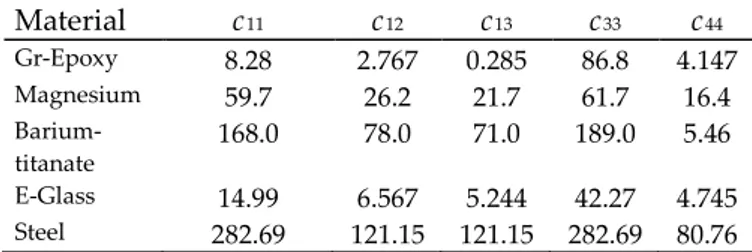
Table 1. Values of elastic constants (in GPa) (Behrens,1971; Huntington, 1958) Material c11 c12 c13 c33 c44 Gr-Epoxy 8.28 2.767 0.285 86.8 4.147 Magnesium 59.7 26.2 21.7 61.7 16.4 Barium-titanate 168.0 78.0 71.0 189.0 5.46 E-Glass 14.99 6.567 5.244 42.27 4.745 Steel 282.69 121.15 121.15 282.69 80.76
The isotropic material selected is steel with the elastic modulus of 210 GPa and the Poisson’s ratio 0.3. For the transversely isotropic materials considered in this paper. the numerical values of elastic constants are used for different materials and tabulated in Table 1.
Some of the calculated results obtained from the solution of the continuous contact problem described in the previous section for various dimensionless quantities such as a/b, h1/h2 are
shown in Figs. 2..4. It is assumed that both of transversely isotropic layers occur the same materials, the contact along the interface is frictionless.
0 0,5 1 1,5 2 2,5 3 3,5 4 4,5 5 0 0,2 0,4 0,6 0,8 1
r/a
p
(r
)/
p
0a/b=0.4
a/b=0.5
a/b=0.6
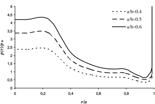
Figure 2. Pressure distribution for a/b=0.4, 0.5, 0.6 and h1/h2=0.2 in a graphite-epoxy
Fig. 2 shows the variation of the normalized pressure value, p(r)/p0 between radius of rigid
cylindrical block with r/a for h1/h2=0.2 and
different a/b for graphite-epoxy. As seen in Fig. 2, the normalized pressure under rigid stamp decreases with increasing r/a. The pressure
values is maximum for r/a=0.245486. Normalized pressure decreases between r/a=0.245486 and r/a=1. For a fixed value of h1/h2=0.2, the contact
area, a/b increases with normalized pressure, p(r)/p0. 0 0,5 1 1,5 2 2,5 3 3,5 4 0 0,1 0,2 0,3 0,4 0,5 0,6 0,7 0,8 0,9 1 r/a p (r )/ p0 h1/h2=0.5 h1/h2=1 h1/h2=2
Figure 3. Pressure distribution for h1/h2=0.5, 1, 2 and a/b=0.5 in a graphite-epoxy
Further results for the normalized pressure
distribution is shown in Fig. 3, for a fixed value of a/b=0.5. The figure shows p(r)/p
0 for three
h1/h2=0.5, 1, 2 in a graphite-epoxy. It appears
that, for a fixed value of a/b and increasing layers
thickness ratio, p(r)/p0 increasing with
decreasing r/a. However increasing of p(r)/p0 is
negligible. 0 0,5 1 1,5 2 2,5 3 3,5 4 4,5 5 0 0,2 0,4 0,6 0,8 1
r/a
p
(r
)/
p
0Magnezyum
Grafit Epoksi
E Camı
Baryum Titanat
Çelik
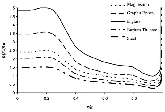
Figure 4. Pressure distribution for a/b=0.4 and h1/h2=0.3 in different materials
Fig.4 shows the normalized pressure, p(r)/p0,
between radius of rigid stamp, r/a for h1/h2=0.3
and a/b=0.4 in different materials. For steel E=210 GPa and ν=0.3 are given. As it can be seen in the figure that the normalized pressure has a sharp peak at r/a=0.245486. Normalized pressure values are bigger in E-glass layer while it is smaller in other materials. There is a small difference between pressure distribution for magnesium and barium titanate layers.
Acknowledgments
This paper was produced from the master thesis entitled “The Behavior of Transversely Isotropic Layers Resting on Circular Supported Under Effective a Rijid Cylinder Block” under supervising Assoc. Prof. Dr. Behcet DAĞHAN. The programming and evaluating results were carried out by Assoc. Prof. Dr. Mesut UYANER.
REFERENCES
Adams, G.G., Zeid, I., 1984, “An Elastic Punch Moving Across the Surface of a Semi-Infinite Solid”, Journal of Applied Mechanics, 51, 622-629
Aksoğan, O., Akavci, S.S., Becker, A.A., 1997, “The solution of the non-symmetrical contact problem of an elastic layer supported by two elastic quarter planes using three different methods”, Journal of Faculty of Engineering-Architecture, Çukurova Univ. Vol. 12, No.2, 1-13.
Avci, A., Bulu, A., Yapici, A., 2006a, "Axisymmetric smooth contact for an elastic isotropic infinite hollow cylinder compressed by an outer rigid ring with circular profile", Acta Mechanica Sinica, Vol. 22, No.1, 46-53.
Avci, A., Yapici, A., Uyaner, M., 2006b, "Contact Problem for a Transversely Isotropic Cylinder Radially Compressed by a Rigid Toroidal Indenter", Science and Engineering of Composite Materials, Vol. 13, 103-113.
Bakırtaş, K., 1980, “The Problem of a an Rigid Punch an a Non-Homogeneous Elastic Half-Space”, International Journal of Engineering Science, Vol. 18, 597-610.
Magnesium Graphit Epoxy E-glass
Barium Titanate Steel
Behrens, E., 1971, “Elastic constants of fiber-reinforced composite with transversely isotropic constituents”, Journal of Applied Mechanics, Vol. 38, 1062-1065.
Civelek, M. B., 1972, The axi-symmetric contact problem for an elastic layer on a frictionless half-space, Ph.D. Thesis, Lehigh University.
Civelek, M.B., Erdoğan, F., 1974, “The Axially Symmetric Double Contact Problem for Frictionless Elastic Layer”, International. Journal Solids and Structures, Vol. 10, 639-645.
Dhaliwal, R.S., 1970, “Punch Problem for an Elastic Layer Overlying an Elastic Foundation”, International Journal of Engineering Science, Vol. 8, 273-288.
Erdoğan, F., Gupta, G.D., 1972, “On The Numerical Solution of Singular Integral Equation”, Quarterly Journal of Applied Mathematics, Vol. 29, 525-534.
Fabrikant, V.I., Sankar, T.S., 1986, “Concentrated Force Underneath a Punch Bonded to a Transversely Isotropic Half-Space” International Journal of Engineering Science, Vol. 24, 111-117.
Geçit, M.R., Erdoğan, F., 1978, “Frictionless Contact Problem for an Elastic Layer under Axi-symmetric Loading”, International Journal of Solids and Structures, Vol. 14, 771-785.
Geçit, M.R., 1986, “The Axi-symmetric Double Contact Problem for a Frictionless Elastic Layer Indented by an Elastic Layer”, International Journal of Engineering Science, Vol. 24, 1571-1584.
Huntington, H. B., 1958, “The Elastic Constants of Crystals”, International Solid State Physics, Advances in Research and Development, F. Seitz and D. Turnbull (eds.), Vol. 7, 231-351.
Kahya, V., Birinci, A., Erdöl, R., 2001, “Frictionless Contact Problem Between an Elastic Layer Bonded to a Rigid Support and a Rigid Stamp”, Mathematical & Computational Applications, Vol. 6, No.1, 13-22.
Lekhnitskii, S.G., 1981, Theory of elasticity of an anisotropic body, Moscow, Mir Publishers Muskhelishvilli, N.I., 1953, Singular Integral Equations, P. Noordhoff, Groningen.
Ratwani, M., Erdoğan, F., 1973, “On the Plane Contact Problem for a Frictionless Elastic Layer”, International Journal of Solids and Structures, Vol. 9, 921-936.
Uyaner, M., Akdemir, A., Erim, S., Avci, A., 2000, “Plastic Zones In A Transversely Isotropic Solid Cylinder Containing a Ring Shaped Crack”, International Journal of Fracture, Vol. 106, 161-175. Uyaner, M., Ataberk, N., Avci, A., 2002, "Plastic Zones for a Penny-Shaped Crack in a Transversely
Isotropic Layer Bonded Between Two Isotropic Half Planes", European Journal of Mechanics-A Solids, Vol. 21, 401-410.