RADIATION FIELDS OF A COMPLEX SOURCE IN
2-D CIRCULAR RADOME WITH METAL
GRATINGS
A THESIS
SUBMITTED TO THE DEPARTMENT OF ELECTRICAL AND
ELECTRONICS ENGINEERING
AND THE INSTITUTE OF ENGINEERING AND SCIENCES
OF BILKENT UNIVERSITY
IN PARTIAL FULFILLMENT 6F THE REQUIREMENTS
FOR TH£ DEGREE OF
MASTER OF SCIENCE
By
Slim Ouarddnt
August 1997
RADIATION FIELDS OF A COMPLEX SOURCE IN
2-D CIRCULAR RADOME WITH METAL GRATINGS
A THESIS
SUBMITTED TO THE DEPARTMENT OF ELECTRICAL AND
ELECTRONICS ENGINEERING
AND THE INSTITUTE OF ENGINEERING AND SCIENCES
OF BILKENT UNIVERSITY
IN PARTIAL FULFILLMENT OF THE REQUIREMENTS
FOR THE DEGREE OF
MASTER OF SCIENCE
By
Slim Oiiarclani / A u g u s t 1997
τ κ ^Sdo
•R3
оеп> Q Q' '■i 3 511
I certify that I have read this thesis and that in my opinion it is fully adequate, in scope and in quality, as a thesis for the degree of Master of Science.
Prof. Dr. Ayhan Altmtaş(Supervisor)
I certify that I have read this thesis and that in my opinion it is fully adequate, in scope and in quality, as a thesis for the degree of Master of Science.
Dr. VÎa'dimir Yurchenko(Co-Supervisor)
I certify that I have read this thesis and that in my 02:>inion it is fully adequate, in scojDe and in quality, as a thesis for the degree of Master of Science.
Assoc. Prof. Dr. İrşadi Aksun
I certify that I have read this thesis and that in my opinion it is fully adequate, in scope and in quality, as a thesis for the degree of Master of Science.
y-. ID ^ f
Assoc. Prof. Dr. Gülbin Dural
Approved for the Institute of Engineering and Sciences:
Prof. Dr. Mehmet Baray
11
I certify that I have read this thesis and that in my opinion it is fully adequate, in scope and in quality, as a thesis for the degree of Master of Science.
A .
Prof. Dr. Ayhan Altıntaş(Supervisor)
I certify that I have read this thesis and that in my opinion it is fully adequate, in scope and in quality, as a thesis for the degree of Master of Science.
______________________ Dr. m aolmii' Yurchenko(Co-Supervisor)
I certify that I have read this thesis and that in my oi^inion it is fully adequate, in scope and in quality, as a thesis for the degree of Mcister of Science.
( K-> cu!lk.
Assoc. Prof. Dr. irşadı Aksun
I certify that I have read this thesis and that in my opinion it is fully adequate, in scope and in quality, as a thesis for the degree of Master of Science.
Lssoc. Prof. Dr. Gülbin Dural
Approved for the Institute of Engineering cind Sciences:
Prof. Dr. Mehmet 6 ^ a y
ABSTRACT
R A D IA T IO N FIELD S O F A C O M P L E X S O U R C E IN 2-D C IR C U L A R R A D O M E W IT H M E T A L G R A T IN G S
Slim Ouardani
M .S . in Electrical and Electronics Engineering Supervisors:
Prof. Dr. Ayhan Altıntaş Dr. Vladim ir Yurchenko
August 1997
In this thesis, the transmission effect of ci two-dimensional circular radome with periodic metal gratings is analyzed. We started with the study of gratings con sisting of periodic arrays ol thin lossy strips surrounded by vacuum. Then we investigated the behavior ol such gratings if a dielectric hiyer is inserted between them. Complex line sources are considered to simulate directed beam fields used in practice. The fields on the interior and exterior sides of the radome are repre sented by modal cylindrical waves. Taking advantage of theoretical considerations recently published, we propose an approximate method and stress the numerical aspect. Data is obtained for the far field solutions and the directivity, and their dependences on different radome parameters. It appecirs that directivity varia tions with beam orientation are deci'eased considerably by a proper insertion of the dielectric layer.
Keywords : Dielectric radome, metal gratings, directivity.
ÖZET
İKİ B O Y U T L U M E T A L IZ G A R A L I D A İR E S E L R A D O M İÇ İN D E K İ B İR K A R M A Ş IK K A Y N A Ğ IN IŞIN IM I
Slim Oıiardani
Elektrik ve Elektronik Mühendisliği Bölümü Yüksek Lisans Tez Yöneticileri:
Prof. Dr. Ayhan Altıntaş Dr. Vladim ir Yurchenko
Ağustos 1997
Bu tezde, iki boyutlu, periodik metal ızgaralı dairesel rcidomlarm cilan geçirgenliği incelenmiştir. Öncelikle, ızgaraların periodik ve kayıplı olduğu ve çevrelerinde ayrıca yalıtkan olmadığı durum incelenmiş, daha sonra bu ızgaralm arasına yalıtkan tabaka konulması durumu çözülmüştür. Pratikte kullanılcin yönlü hüzme kaynağının benzetimi için karmaşık noktaya yerleştirilmiş kaynak modeli kul lanılmıştır. Çözüm için metal ızgara ve yalıtkan tabakadan oluşan radom ge ometrisinin içinde ve dışındaki alanlar silindirik dalgalar şeklinde yazılmıştır. Dciha sonra literatürdeki son katkılardan esinlenilerek yaklaşık ama nümerik olarak verimli bir yöntem uygulanmıştır. Işınım alanının değişik radom param- etleri ile değişimi hususunda veriler elde edilmiştir. Bu ve,rilere göre hüzme kazancının, hüzmenin yönüe göre değişmesi, metal ızgara arasına konulan ycilıtkan levha ile kontrol edilebilmektedir.
Anahtar Kelimeler : Yalıtkan radom, metal ızgaralar, işimin kazancı
ACKNOWLEDGEMENT
I would like to express my deep gratitude to rny supervisors Dr. Vlademir Yurchenko and Prof. Dr. Ayhan Altıntaş for their guidcince, suggestions cind valuable encouragement throughout the development of this thesis.
I would like to thank Assoc. Prof. Dr. Irşadi Aksun ¿ind Assoc. Prof. Dr. Gülbin Dural lor reading and commenting on the thesis and for the honor they gave me by presiding the jury.
I am also indebted to my family for their patience and support.
Sincere thanks are also extended to everybody who has helped in the development of this the,sis.
VI
Contents
1 INTRODUCTION
1
2 ANALYSIS OF TRANSMISSION THROUGH A RADOME
WITH METAL GRATINGS
5
2.1 Radiation Through a Circular Radome of a Thin Periodic Metal
Grating 6
2.2 Genercil Form of Boundary Conditions 9 2.3 Algebraic Solution of the P rob lem ... 11 2.4 Radiation Through A Rcidome of Periodic Metal-Dielectric Grat
ing ... 13
3 NUMERICAL RESULTS AND DISCUSSION
16
3.1 Radomes of Periodic Metal Gratings 18 3.2 Radomes of Periodic Metal-Dielectric G r a t i n g ... 364 CONCLUSION
44
List of Figures
2.1 Geometry of the comi^Iex line s o u r c e ... 6 2.2 Geometry of circular pei ioclic metal g r a tin g s ... 7 2.3 a.nd rjT functions of ^ ... 11 2.4 Geometry of a circular radome with periodic metal gratings 15 2.5 and Vt functions oi (/ )... 15 3.1 Normalized power at the far zone for a circvdar reflector antenna:
2Rt/Zq = 5 X 10“ '’ , ka = 6.28,?’o = « /2 ,^ 0,^ap - 30 degrees, kb = 0.5... 20 3.2 Normalized power at the far zone for 2 circular opposite strips:
2RrlZo = 5 X 10“ '^, ka - 6.28,ro = o,l‘2,^ = 0,^ap — 30 degrees,
kb = 0.5... 20 3.3 Normalized power at the far zone for a grating consisting of two
resistive strips : ka = 62.8 , kb = 5 , = 0° , 2Rt!Zq = 0.1% ,
(a) Oap = 0.5° , (b) flap = 1°... 21 3.4 Normalized power at the far zone for a grating consisting of three
resistive strips : ka = 62.8 , ¿6 = 5 , /3 = 0° , 2RtIZq - 0.1% ,
(a) flap = 0.5° , (b) flap = 1°... 22
viii
LIST OF FIGURES
IX
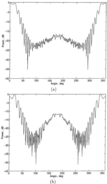
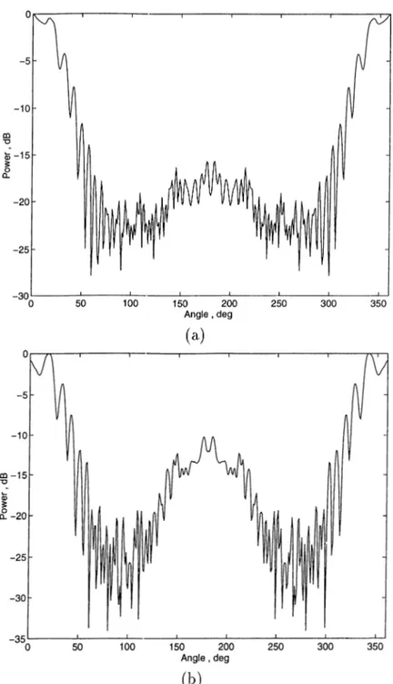
3.5 Normalized power at th<5 far zone for a grating consisting of four resistive strips : ka - 62.8 , kb = 5 , fl = 0° , 2i?y/Zo = 0.1% , (a) 0ap = 0.5° , (b) 0ap = V ... 23 3.6 Normalized power at the far zone for a grating consisting of five
resistive strips : ka = 62.8 , ^6 = 5 , /? = 0° , 2Rt/Zo = 0.1% ,
(a) = 0.5° , (b) Oap = 1°... 24 3.7 Normalized power at the far zone for a grating consisting of two
resistive strips : ka = 62.8 , kb = 5 , /3 = 0° , 2Rt/Zo = 10% , (a)
= 0.5° , (b) dap = 1° , (c) 0ap = 1.5°... 25 3.8 Normalized power at the far zone for a grating consisting of three
resistive strips : ka = 62.8 , kb — 5 , /3 — 0° , 2Rt/Zq = 10% , (a) 9ap = 0..5° , (b) 0ap = 1° , (c) 9ap = l.-5°... 26 3.9 Normalized power ¿it the far zone for ¿i gi’citing consisting of four
resistive strips: ka = 62.8 , kb = 5 , /3 = 0° , 2RtIZo = 10% , (a) 0ap = 0.5° , (b) 9ap = 1° , (c) 6ap = 1.5°... 27 3.10 Normalized power at the far zone for a grating consisting of five
resistive strips : ka = 62.8 , kb = 5 , /3 = 0° , 2RxIZq = 10% , (a)
Oap = 0.5° , (b) 0ap = 1° , (c) 0ap = 1.5°... 28 3.11 Directivity versus Angular Width of Strips {0ap) '■ ka = 62.8 ,
¿6 = 5 , = 0° , 2Rt/Zo = 10%. 30 3.12 Directivity versus Angular Width of Strips (0ap) : ka — 62.8 ,
¿¿ = 5 , ^ = 0 ° , 2RtIZo = 1%. 30
3.13 Directivity versus Angular Width of Strips (0ap) : ka — 62.8 ,
kb = 5 ,/3 = 0° , 2 Rt/Zo = 0.1%... 31 3.14 Directivity versus Beam Direction for a grating consisting of two
resistive strips : ka = 62.8 , kb = 5 , 0ap = 1° , (a) 2RtIZq = 1%
3.15 Directivity versus Beam Direction for a grating consisting of three resistive strij^s : ka = 62.8 , kb = 5 , Ogp = 1° , (a) 2RtIZq — 1%
, (b) 2RtIZo = 10%... 33 3.16 Directivity versus Beam Direction for a grating consisting of four
resistive strips : ka = 62.8 , kb = 5 , Oap = 1° , (a) 2RtIZq — 1%
, (b) 2Rt!Zo = 10%... 34 3.17 Directivity versus Beam Direction for a grating consisting of five
resistive strips : ka = 62.8 , kb = 5 , Oap = 1° > (a) 2Rt/Zq = 1%
, (b) 2RtIZo = 10%... 35
3.18 Normalized Power at the far zone for circular reflector antenna;
2Rt/Zo = 5 X lO-'’ , ka = 6.28 , ro = a /2 , ^ = 0 , Oap = 30° ,
kb = 0.5... 38 3.19 Directivity versus Thickness for a circular dielectric radome ka =
62.8, A:ro = 0,kb = 5,c, = 4 + f ... 38 3.20 Directivity versus Thickness for a circular dielectric radome ka —
62.8, fcro = 0,kb = 5,e; = 4 + fO.5. .39 3.21 Dii’ectivity versus Thickness for a circular dielectric radome ka =
Q2.8Mo = 0,kb = 10,e, =. 4 + ¿0.5... 39 3.22 Directivity versus Thickness for a circular dielectric radome ka =
62.8, kro = 0,kb = 15,e; = 4 + ¿0.5... 40 3.23 Directivity versus Thickness for a circular dielectric radome ka —
62.8, kro = 0,kb = 20,e, = 4 + ¿0.5... 40 3.24 Directivity versus Dielectric Thickness for a circular
metal-dielectric radome... 41 3.25 Directivity versus Angular Width of metal strips for a circular
metal-dielectric radome... 41
LIST OF FIGURES
XI
3.26 Directivity versus Beam Direction for a circular radome: 9ap = 0.5°;solid:metal in free si5ace;dashed:metal-diel c,. = 4;dash dotted:metal-diel ir = 4 + ¿0.5... 42 3.27 Directivity versus Beam Direction for a circular radome: 9ap —
2°;solid:metal in free space;dcxshed:metcd-diel e',. = 4;dash dotted:rnetal-diel i,· = 4 + ¿0.5... 42 3.28 Directivity versus Beam Direction for a circular rcidome: 9ap —
5°;solid:metal in free space;dashed:metal-diel e,. = 4;dash dotted:metal-diel ir = 4 + ¿0.5... 43
Chapter 1
INTRODUCTION
The transmission and reflection of the wave propagating through single and mul tiple dielectric layer systems is always an interesting subject of study which finds many applications. These systems have been studied since the early development of the wave liropagation, especially the electromagnetic waves. The layers can be planar, cylindrical or spherical, of non uniform thickness, open or closed in the form of shells.
Open layers may affect the propagation process by transmission through or guiding within them; closed layers may exhibit, in addition, phenomena at tributable to resonance, either inside the layers themselves or in the cavity en closed by the layers. One of the most important applications of the multiple dielectric layer systems is the Fabry-Parot interferometer, which has been used in the optical spectrum analyzer for a long time. When the dielectric layers are stacked in a periodic manner, a special class of laj^ered media which exhibits many interesting ¡phenomena has been found to be very useful. The examples are the Bragg reflector and various filters, such as frequency selective filters, which are capable of modifying the transmission within a certain range of frequency.
Theory of planarly layered media is a classical example which is found in textbooks, however that of cylindrically and spherically layered media was done
Chapter 1. INTRODUCTION
not long ago[l]. The concentration was on the scattering of point sources by curved layers with special interest in the cylindrical and spherical structures.
The effect of a cylindrical dielectric layer on the penetration of electromagnetic waves hcis been extensively aniilyzed for the last few years, due to its potential applications such as in the study of the performance of a radar cuitenna enclosed by a radome. A radome is a dielectric shell which is used to protect the rcidar from rain, wind, sun, etc. In the presence of the radome, the radiation pattern of the radar antenna is distorted and a shift in the beam pointing angle of the radcir appears [2].In practice, a j)recise analysis of radome performance is diffi cult, and nearly imi^ossible, because the general shape of the radome layer does not lit into the frame suitable for e.xact analysis. One must therefore resort to some approximation methods. The basic principle of approximation is to find a canonical configuration to approximate the surface of the dielectric layer. In [2] a method of modal cylindrical wave spectrum, which is an extension of the plane wave spectrum surface integration technique [3], is applied to the analysis of a two-dimensional elliptic radome. In [4] analysis of two-dimensioiicxl circu- hir dielectric layer was performed to account for the curvature effect which was ignored in the previous studies, and correct slab transmission coefficient that improve local plane slab hypothesis was found. Proj^agation of Gaussian beam through dielectric plane layer [5] and circular cylindrical layer [6] was cinalyzed. Narrow beam has been employed as basis elements in the synthesis procedure, and each beam element has been propagated through the layer to the observer by non uniform complex ray asymptotics. In [7] equivalence partial angular har monic and ray-type Green’s functions were investigated focusing on the relation between periodic and non periodic Green’s functions for a closed (0 < < 2Tr) and open ( —oo < 6 < oo) shell, respectively. Far field solutions for real and com plex line sources enclosed by a two-dimensional circular radome are obtained in [8]. Gylindrical functions are used to represent the incident field cind the scattered fields in the inner, middle, and outer regions. Boundary conditions are cipplied to the fields and analytical solutions to the problem is obtained.
Several types of boundary conditions have been developed for layered sheets to calculate the fields scattered or radiated by systems of thin layers. If the layers are modeled as infinitesimally thin structures described in terms of a set
Chapter 1. INTRODUCTION
of boundary conditions, the computational problem becomes much less intense. Generalized impedance boundary conditions are derived for planar, magnetic dielectric slab grounded by a perfect electric conducting plane and for a magnetic dielectric coated perfect electric conducting cylinder [9]. Generalized resistive boundary conditions are also obl.ained for a planar, transparent dielectric slab. Other types of boundary conditions and the corresponding integrcil equations apply to penetrable sheets, and they are described as transmission boundary conditions. Curvature corrected boundary conditions for combined resistive and conductive sheets are described in [10]. In [11], attention was focused in the case of a layered sheet with different reflection properties characterizing its two faces. The boundary conditions involve only the tangential components of the fields and a set of the corresponding surface integral equations is provided for impenetrable and penetrable sheets. These boundary conditions can also reduce to the special case of sheets with identical reflection coefficients from both sides.
So far, a brief review of the problem of electromagnetic wave penetration through dielectric la.yer is given. In recent years the diffraction analysis of elec tromagnetic waves by dielectric gratings have been intensively investigated as well. Nowadays such structures are gaining widespread use as in frequency se lective filters, radomes and polarizers. In [12] the problem of scattering from a resistive grating is formulated in the spectral domain, where the convolution form of the integral equation for the scattered field reduces to a product form which can be solved by moment method techniques. Resistive boundary conditions are used with a constant surface resistance defined for the strips that are thin com pared to the attenuation length. The transmission and reflection coefficients of the array of strips are determined from the scattered fields. Later this approach was extended to multi-layered resistive strip gi'citings [13], and in [14] the study of gratings consisting of a periodic array of thin lossy strips with arbitrary cross section is provided.
In this study, the effect of a two-dimensional circular radome with metcil grat ings, on the propagation of electromagnetic fields radiated by a complex line source is investigated. The fields on the concave and convex sides of the radome are represented by modal cylindrical waves. Boundary conditions provided in
Chapter 1. INTRODUCTION
[11] are used to derive the analytic solution of the problem. At first, the trans mission effect of circular gratings consisting of periodic arrays of lossy strips is considered. Two cases are described,high conductive (non-perfect metcvl) and high resistive (poor dielectric) thin strips. Finally the original problem is cuia- lyzed. Although we employed approximate boundary conditions to establish the field on the exterior side of the radome due to the source located on the interior side, the numerical data obtained justify strongly the validity of the method. Another important thing is that the method is effective for any number (> 1) of the strips with any angular width from 0 to ‘Ztt. This enables us to simulate
different structures already studied in literature such as reflector antennas [15] and 2-D circular dielectric radome [8], and compare with the techniques used to solve for these geometries. The size of the matrix is determined l^y the radius of curvature and fairly large structures can be treated with guaranteed accuracy. Numerical results for the far fields and directivity of various structures are ob tained. Thickness variations are also included to give a better understanding of the models. Compcirisons are given to study the validity of the method.
The outline of this thesis is as follows: In chapter 2 we introduce the bcisic concept of the method and the formulation of the problem. Numerical results are presented in chapter 3. Main conclusions follow in chapter 4.
Throughout the analysis, a sinusoidally-varying time dependence e is as sumed and suppressed.
Chapter 2
ANALYSIS OF
TRANSMISSION THROUGH
A RADOM E W ITH METAL
GRATINGS
In this analysis, complex line source is considered to simulate directed beam fields. The primary wave fields are repr<;sented as expansion series of cylindrical waves, and then the effect of transmission through the radome is analyzed to evaluate the radiation fields. Formulation of the problem is carried out for tliin periodic metal gratings and then extended to the case of periodic metal-dielectric radome.
Chapter 2. ANALYSIS OF TRANSMISSION THROUGH
...
2.1
Radiation Through a Circular Radome of
a Thin Periodic Metal Grating
In Figure 2.1 a line source is placed at the comple.x position r^s which is given b,y Tj = Fo + ib = r'ox + ib{cosfIx + sinfly) (2.1) where the parameter 6 is a measure of the source directivity, cuid the angle ¡1 represents the direction of the becim.
P'igure 2.1: Geometry of the comj^lex line source
Depending on the polarization, we denote by U the Fb or IL of the fields. The incident field due to the line source of amplitude C at the complex position
fs is given by:
U‘" { r , = C f l i ' \ k „ \ f - r , n
(2.2)
where ko is the free space wave number and Hq{ Kt) is the Hankel function of the
Chapter 2, ANALYSIS OF TRANSMISSION THROUGH
...
as where "s ~ \¡7'q — 6^ + 2ibl\^COsfi _i^rQ-\-ihcosl3 Vs = COS ( --- ) (2.;3) (2.4) (2.5)Figure 2.2: Geometiy of circular periodic metal gratings
Figure 2.2 shows a grating cojisisting of an array of circular thin metal strips surrounded by vacuum. The perfectly conducting strips have zero thickness and angular width 29ap· The array is ])eriodic with period (¡)q. To solve the problem of
a complex line source rcidiating through periodic metal grating, the scattered field should satisfy the Helmholtz equation, the Neumann or Dirichlet type boundary
Chapter 2. ANALYSIS OF TRANSMISSION THROUGH
...
condition on the strips, the continuity condition at the slots and the radiation condition at infinity. The scattered field can be expressed in integral Idrm by imposing the boundary condition as follows
/ JE ir')G o(7-?}ch^,7-e JM
M
(2.6)
in El-polarization dU‘^‘^(i^) d dn (2.7) in H-polarization where h is the outer normal, Je,h{t) are the unknown current densities, G o {f,r')is the 2-D Green’s function (i.e ^HQ^\k\f — 7''|)) and the contour M is taken as the surface of all the scatterers.
Equations (2.6) and (2.7) are widely known and can be solved numerically by the method of moments (M oM ). Unfortunately MoM solutions lead to matrixes of great order N or increase the computation time due to massive numerical inte gration. In addition the problem often becomes ill-posed and does not guarantee convergence of the solution when N oo. I'br these reasons, it is recommended to use other methods to calculate the radiated fields.
For our geometry the total field can be expressed as follows ¿/¿nc(-) ^ ^
(2.8)
U"^(f) r > a .
The scattered field satisfies the 2-D Helmholtz equation
(V^ + = 0. (2.9) Due to the axial symmetry of the problem it is expanded in series form as
rnJn{kor)U'"*’ r < a
C /-(f) = ^
^ U i(^ \ k o r)Fruj)
(
2
.10
) r > a .Chapter 2. ANALYSIS OF TRANSMISSION THROUGH
...
where r'n and are the unknown coefficients to be determined by the boundary conditions at 7’ = a.
In region 1 (?’ < a) Bessel function is chosen to represent the standing wave nature of the scattered field, wherecis in region 2 (r > a) Hankel function is chosen to satisfy the radiation condition at infinity.
Hence, the total field in region 1 is given by
+ 7’„./„(^^or)]e'"^ |7’,| < /■ < « (2.11)
n
and in region 2 cis
(2.1 2)
2.2
General Form of Boundary Conditions
The boundary conditions to be used are established in [11] for the analysis of imperfectly conducting layers. We do realize that the set of bounchiry conditions available are valid for lossy materials, nevertheless the method can be generalized to cpiite good conductors. Actually, the concept of perfectly conducting mate rial and of a perfectly conducting and infinitely thin screen is not always well understood [16]. For example, in the far infrared, gold is generally considered as infinitely conducting, however a very thin gold strip, like that found in tele scopes, can be melted by a laser beam. Thus for practical purposes if a metal is supposed to have the same permittivity and permeability of free space and a real conductivity <r(a model often used in the far infra red cuid microwave ranges), it is equivalent to a lossy dielectric with relative permittivity e,. = 1 + fo/eoa^.From now on, we consider imperfectly conducting metals.
The boundary conditions we shall be using are given in the following form
<ETirJ)>=RTir,<j>)JT{r,<l>) (2.13) < Hrir, </>) > = ,ST(r, <f>)MTir, </>) (2.14)
Chapter 2. ANALYSIS OF TRANSMISSION THROUGH ...
10
which relates the average tangential fields
1
< E rir, (/)) > = -[E2T(r, (j)) + E irir, (j))]
< H rir, Cj>) > = ^[f/2r(r, + / /i tO·, <!>)]
(2.15) (2.16) to the currents defined by the field jumps
./x(r, cj>) = h X [ //27-(r, <i>) - //ir (r , <!>)] (2.17) M r(r, (f)) = ~h X [E
2
T{r, (j)) - Eirir, (j))] (2.18)Here the subscript 1 or 2 denotes the fields in respective regions, and R j and St
have the interpretation of the electric resistivity and magnetic conductivity of the interface separating regions 1 and 2. They can be regcirded as phenomenological parameters which can be determined experimental^ through the measurement of the reflection and transmission coefficients, or evaluated analytically according to [11].
An alternative version of this set of boundary conditions is written as
h X [Hriir, <!>) - H M r, <!>)] = 6 '(a ct>)[E2T{r, c!>) + E Mf 9^)1 (2.19) - n X [i?2T(r, (¡)) - Errir, V))] - T]T{r, ^)[H2T{r, (j>) + HiT{r, (/))] (2.20)
where
^T{r,<l>) = l/i2R.Tir,<j>))
7]T{r, (j)) = l / ( 2,SV(r,</>))
(2.2 1)
(
2
.22
) Obviously, the boundary conditions have to be imposed on the strips. In our geometry, these strips form a periodic open contour, thus it is necesscuy for I^tand T}T to have a periodic step function of (j) to account for the continuity of the total electric and magnetic fields at the slots (see P’igure 2.3).
In the case of E polarization, (2.23) and (2.24) will be relating ii'. and H,j, — in the following way
Chapter 2. ANALYSIS OF TRANSMISSION THROUGH ...
11
FTU c <!>) - E i.rir, <j>) --= T^rir, <^)[//20(r, <p) + //i0 (r , m -= a (2.24) with A
0
ii> e
s
(2.2.5) (2.26) 8 \i<t>e M 0 if e -5'.Note that in the limit case A —> oo and —> 0 the boundary conditions reduce to the Dirichlet boundary condition for only perfectly conducting material Ey —
E2 — 0.
4t(<|)) ,T)t(<1))
A,5
zILl -0u|,
2 0ap IJL 2
Figure 2..3; and r/T functions of (j)
2.3
Algebraic Solution of the Problem
To find the coefficients and it is convenient to write the functions and ?;2’ ((/>) in their Fourier series expansion
inL(j)
(2.27) and
Chapter 2. ANALYSIS OF TRANSMISSION THROUGH
...
12
where and iT „,(v r„) = A , (6) C\ Ogp ^ 00 if n = 0 ^sin{nL0ap) if n ^ 0 r __ 27T “ 0 0 ·Recalling that a periodic function / with period 2tt and another cj with period
(j)o where divides 2% by an integer L are written as ./’ = and g = J2n
then their product p = f g can be expanded in a generalized Fourier series
P = EnPne‘"^with Pn = T,rn fn-rnLgm
Therefore the expansion of (2.23) and (2.24) can be performed easily and we are led to T ^^0 Em ^Tm^n—mL^n—mL ^'nUn T *■^0 Em ItTnAn—’n^LlJn—mL — Zn. ^ g-^ n "f" ^ 0 ^ ^ ^Tm - rn L ^ n - rn L ( 2 . 2 9 ) m t n ^ n + ' ^ m VTm^n-mL''^n-mL ~ VT^n‘^'n -m L D n -m L ~ . r/ ^/^771 - mL^n- mL ^^0 m (2.30) where Vn = 4^Hkoa) y ; = j P i k o a ) Zn = Jn{hrs)e~^"·^^
and Zountrinsic impechince of free space .
Note that the derivatives are with respect to the argument. Keeping only
Ntr = '2N + 1 terms in the Fourier series(?i < A^), we get ?·„ and tn by solv
Chapter 2. ANALYSIS OF TRANSMISSION THROUGH ...
13
The boundary conditions we luwe been using so far, rewritten here for conve nience are
-i^2r/> ~ Hi,p = I,t(F2z + Fiz) (2.31)
E'2z — Fiz = Vt{H2^ + Hi,j,). (2.32) By setting 7]T = 0, 7^ 0 we obtain the well known set of equations for a thin dielectric resistive sheet (i.e a sheid of high conductivity and its resistivity is siricill compared to free space impedcuice)
//20 - Hl(j> ^t{F 2z + Flz)
F2Z — Fiz
(2.33) (2..34) With these two equations we Ccin solve for r„ and independently. The field of interest is the one at the far zoikj which includes We obtained the following
equation in
XuVn - XnVn
tn T N Aq ^ ^ ^TnXn—mLin—rnL —XuVn - XuVn
Un m Vr,
where ?/„, and are as the ones used in (2.29) and (2.30).
(2.3.3)
2.4
Radiation Through A Radome of Periodic
Metal-Dielectric Grating
Previously, we have considered the problem of thin periodic metal grating. The strips are modeled as infinitely thin structures described in terms of a set of boundary conditions relating the fields from the interior and exterior sides by the two coefficients Rj· cincl St (2.13 and 2.14) known as electric resistivity and mag netic conductivit}^ respectively. While treating thin structures, it is convenient to define real constant resistivities and conductivities for the strips, however for a hiyer of finite thickness, this assumption does not hold because these coefficients depend on the microscopic properties and thickness of the layer.
Chapter 2. ANALYSIS OF TRANSMISSION THROUGH
...
14
For a dielectric/rna.gnetic liiyer characterized by niciterial parameters e:, p and thickness h, the respective values of Rt and St are
2 V e 2 W 6o/^o .5V = h / - c o t ( i , / 4 ^ W . )
zu/ i 2 y cofiQ
which can be written as
where Rt = ' - Z c o t i k ’^ ) i l , ,h Si' = - — cot ( k—) 2 Z 2 ’ Z — Zq/\fCr k = ko\/^· (2.36) (2.37) (2.38) (2.39)
Surely the use of these values for the parameters Rt and St have practical advantages such as the choice of the metal strips characteristics and thickness. Also, we can now insert dielectric between the strips (see Figure 2.4). This will enable us to investigate the (effect of a circular dielectric ra.dome with metal grating, which is the aim of this thesis.
The formulation of the problem for such geometry is carried out exactly as that for thin metal gratings, except that I^t = l/(2 i? i) and 7]t = 1/(25V) will have a different function of 4> from that of Figure 2.3. In this case ^t Vt
now a periodic function of <j) as shown in Figure 2.5 The Fourier series coefficients (^t„ ’s are given as
(A „, - A , ) 2 ^ + A , if?i = 0
^Tn = 4>o
i^rn
if
0
(2.40) and the coefficients as
Chcipter 2. ANALYSIS OF TRANSMISSION THRO UGH ...
15
VT„ (Sm - if n = 0 'PO (¿m -- Ss)^sin{nLO,,,,) if n ^ 0 (2.41)Figure 2.4: Geometry of a circular radome with periodic metal gratings ^t((|)) ,t| t((())
A m. 6iii
As.6s
2
0ap IJL 2Figure 2.5: (fy and r\T functions of 0
Chapter 3
NUM ERICAL RESULTS AND
DISCUSSION
As mentioned in the introduction, the aim of this study is to analyze the effect of cl metal-dielectric periodic radome on the transmission of electromagnetic fields radiated by a complex line source placed inside this structure. The subject is discussed in terms of normalized power at the far zone and the directivity, which represent two important parameters in design problems. The associated formula lor the normalized power pattern is given as
Norm — (3.1
For far field observation {kr 1) the total electric field can be reduced by replacing the Hankel function H lp(kor) by its asymptotic expression. By doing this we obtain
Jko r
inKo V
(3.2)
Chapter 3. NUMERICAL RESULTS AND DISCUSSION
17
which is more convenient for numerical computations.
The directivity, which is the ratio of the maximum radiation intensity to the average radiation intensity, in terms of electric held intensity is given by
D =
2ttI æ;”*'“· p (3.3)Using Parseval’s Relation
^
Jo -'Î0L
I •■^’(0 p
= I ] I «/t· г^
i. (3.4) D can be expressed asD =
LDnax 12
E„ I i,. P '
{■3.5}
In the formulation of the problem, it is stated that exact solutions are not available and are not obtained easily due to several reasons, so approximations have been used to establish the outer helds due to the source enclosed by the radorne. The basic cvpproximation employed is to model the radome as thin layer described by means of boundarj' conditions. The set of boundary conditions provided, relate the inner electric and magnetic helds to the outer ones through two coefficients evaluated by the structure and the material i^roperties of the the Iciyer representing the radome. This approach as alrecidy mentioned considers non perfect metals.
In our investigation, attention was focused on periodic metal gratings since they are strong scatterers compared to dielectrics, esjDecially when the dielectric thickness is half the wave length. Thus metal grating are of primary importance for the scattered helds. In this chapter, the numerical results for two different models of the radome are obtained. The first model is described by thin periodic
Chapter 3. NUMERICAL RESULTS AND DISCUSSION
18
metal gratings surrounded by vacuum, whereas the second model represents a dielectric radome with periodic inetal gratings. For the first model results are given at two levels. Due to high conductivity, resistive boundary conditions are used to obtain the results lor the far field patterns. This simplified boundary condition cissumes the continuity of the electric field through the metal strips. This is due mainly to the fact that the electric field is almost zero on the metal interface so it is considered to be equal at the two faces. This assumption has been widely used in scattering from r<isistive layers and the boundary conditions are often referred as transparency boundary conditions. Then the general boundary conditions are used to show the limitations of the former ones.
3.1
Radomes of Periodic Metal Gratings
In Figure (3.1), the normalized power at the far zone for a circular reflector antenna is obtained(only one strip). This result coincides exactly with the one obtained by solving the integral equations (IE) corresponding to such a geometry [17]. This is expected because our rigorous solution of the problem is in fact the scime as IE solutions. For a non PEC, in the case of E-pol the scattered field is expressed in integral form as
J
J r( f) G if,P)dP
-- £ , r ( r )
+ R T r ir ) (3.6) where J j is the unknown surface current and R is the effective resistance of the scatterer.In our formulation the scattered field is written in series expansion with un known coefficients which are determined by imposing the boundary conditions and we were led to solve the following equation.
Chapter 3. NUMERICAL RESULTS AND DISCUSSION
19
which is equivalent to (3.6) exce])t that the scattered field is expressed in series expansion with separate variables, rather than the compact integral form.
Knowing that our results show good agreement with IE solutions lor the case of a reflector antenna, lurther numerical data for other geometries are obtained.
The normalized power for two circular opposite reflectors is shown in Figure (3.2). The reflectors have the same dimensions as the used to obtain Figure (3.1). The source has the same location and direction as well. A drop in the power is ob.served at (j) = 180°, compared to Figure (3.1).This behavior is understandable due to the presence of the second reflector at that position.
In Figures (3.3) through (3.6) the normalized power at the far zone for gratings consisting of a periodic array of two, three, four and five strips is obtained lor diffei’ent cingular widths when ka = 62.8 , ?'o = 0 , kb = .5 (Beam W idth= 42°)and /3 = 0. The ratio of the strip resistivity to free space impedance is taken as 2Rq'fZo = 0.1%. The same results are obtained lor more resistive strips, 2Rt!Zo = 10% (Figures (3.7) to (3.10)). As observed in these figures, the distortion of the main beam increases with increasing number of strips which is mainly due to the contribution of each strij) to the scattered fields as expected. Increasing the angular width of the strips also increases beam distortion and causes a shift in the main beam direction. It is noticed thcit increasing the resistivity reduces the boresight error (the difference between the cipparent and the distorted beam direction). For strips with ‘I R jjZ o = 0 .1 % and ‘IRt/Zq —
10%, the shift in the main beam direction occurs at an angular width of 2° whereas this behavior appears at an angular width of 3° for strips of higher resistivity
{‘IRtIZq = 10%) and in general the patterns are quite similar for these two cases. This shows that good conductors have greater effect on the distortion of fields which is reasonable since they are stronger scatterers. Another point worth mentioning is that through all these figures, the power at (f> = 180° (opposite to the main beam direction) increases as the angular width increases.
Chapter 3. NUMERICAL RESULTS AND DISCUSSION
20
Figure 3.1: Normalized power at the far zone for a circular reflector antenna:
2Rt¡Zq = 5 X IQ— ka = 6.28,ro = a/2,/9 = 0,^ap = 30 degrees, kb = 0.5.
Figure 3.2: Normalized power at the far zone for 2 circular opposite
Chapter 3. NUMERICAL RESULTS AND DISCUSSION
21
Figure 3.3: Normalized power at the far zone for a grating consisting of two
resistive strips :
ka =62.8
, kb = 5 , /3 = 0° , 2RtIZq =0.1% , (a)
Oap =0.'
(b)
Oap = r .Chapter 3. NUMERICAL RESULTS AND DISCUSSION
22
Figure 3.4: Normalized power at the far zone for a grating consisting of three
resistive strips :
ka= 62.8 , A:6 — 5 , /3 = 0° ,
2RxfZo= 0.1% , (a)
$ap= 0.5° ,
(b)
Qap= r .
Chapter 3. NUMERICAL RESULTS AND DISCUSSION
23
Figure 3.5: Normalized power at the far zone for a grating consisting of four
resistive strips :
ka =62.8
, kb — 5 , /3 = 0° ,2/?x/Zo = 0.1% , (a)
Gap —0.5° ,
(b) Oap = 1°.Chapter 3. NUMERICAL RESULTS AND DISCUSSION
24
Figure 3.6: Normalized jiower at the far zone for a grating consisting of five
resistive strips :
ka= 62.8
, kb =- 5 , ¡3 — 0° , 2RtIZq= 0.1% , (a)
Oap= 0.5° ,
Chapter 3. NUMERICAL RESULTS AND DISCUSSION
25
(a)
Figure 3.7; Normalized power at the far zone for a grating consisting of two
resistive strips :
ka= 62.8 ,
= 5 , /9 = 0° ,
‘¿RtIZq —10% , (a)
Oap —0.5° ,
Chapter 3. NUMERICAL RESULTS AND DISCUSSION
26
Figure 3.8: Normalized power at, the far zone for a grating consi,sting of three
resistive strips :
ka= 62.8 ,
kh — h , /3 = 0° , ‘¿RtIZq —10% , (a)
6ap —0.5° ,
Chapter 3. NUMERICAL RESULTS AND DISCUSSION
27
Figure 3.9: Normalized i)ower at the far zone for a grating consisting of lour
resistive strips:
ka =62.8
, kb = 5 , ¡3 = 0° , 2R/f/Zo -10% , (a)
Oap —0.5° , (b)
Chupter 3. NUMERICAL RESULTS AND DISCUSSION
28
E'igure 3.10: Normalized power at the far zone for a grating consisting of five
resistive strips :
ka= 62.8
, kb ~ 5 , /3 = 0° , 2RtIZq —10% , (a)
вар =0.5° ,
Clmpter 3. NUMERICAL RESULTS AND DISCUSSION
29
After analyzing the far-zone normalized power for different geometries, the directivity, which is a commonly used parameter to measure the overall ability of an antenna to direct radiated power, will be discussed. Figures (3.il),(3.12)and (3.13) present the variations of th<î overall directivity D with angular width for pe riodic gratings of various number of strips with different resistivities. As expected increasing the angular width deci'eases the directivity. However some weak reso- iicuit behavior which is related to the strip width values, around apj^roximately integer multiple of A/2, is observable. Throughout these three figures, the num ber of strips does not affect the directivity up to a critical angular width, related to the linear width of the strip d A /2(if d = A/2 , 0ap = 1-4°, after which the difference becomes more observable. It is found that, at this width the boresight error starts to increase considerably. As observed in these figures that this crit ical angular width becomes wider as the resistivity of the strips increases. It is of 0.8° for materials of resistivity 2RtIZq — 0.1% , 1.5° for 'IRjIZq - 1%, and
2° for 2Rt/Zq = 10%. The directivity at these points is higher as the resistiv
ity decreases. For good conductors (Fig 3.13), we see that the directivity drops shcirply just after zero width cirid then it keeps necirly constant vidue up to the critical width, while it decreases at a lower rate for more resistive materials.
We notice as well that gratings consisting of periodic arrays of two and four strips show very close behavior; however, for gratings of three and five strips the results differ from each other. Similarities appear for two and four strips due to the symmetric structure of the geometry. In addition the beam is directed to the strip and narrow enough that it does not affect the the strips at <j) = ±90°.
The directivity variations versus the beam direction are presented in Figures (3.14) through (3.17) for gratings of two, three four and five strips when ka - 62.8 , T'o — 0 , kb = 5 and Oap = 1°. The data are obtained lor two different resistivities of the strips {2Rt!Zq = 1% and 2RtIZq = 10%). Again, we see that the directivity decreases with increasing resistivity which shows good agreement with the previous results.
Chapter 3. NUMERICAL RESULTS AND DISCUSSION
30
Figure 3.11: Directivity versus Angular Width of Strips {dap) '■ ha = 62.8 , kb = 3
, ^ = 0° ,
2R
t/Z
o=
1 0 %.Figure 3.12: Directivity versus Angular Width of Strips (Oap) : ka — 62.8 , kb
,/3
=0
° , 2RtIZo =1
%.Chapter 3. NUMERICAL RESULTS AND DISCUSSION
31
Figure 3.13: Directivity versus Angular Width of Strips (Oap) : ka = 62.8 , kb = 5
Chapter 3. NUMERICAL RESULTS AND DISCUSSION
32
Figure 3.14: Directivity versus Beam Direction for a grating consisting of two
resistive strips :
ka —62.8
, kb = 5 , Oap =1° , (a)
2RtIZq= 1% , (b)
Chapter 3. NUMERICAL RESULTS AND DISCUSSION
33
Figure 3.15: Directivity versus Beam Direction for a grating consisting of three
resistive strips :
ka =62.8
, kb = 5 , 9ap= 1° , (a)
‘2.Rt/Zq =1% , (b)
Chapter 3. NUMERICAL RESULTS AND DISCUSSION
34
(a)
(b)
Figure 3.16: Directivity versus Beam Direction for a grating consisting oi four
resistive strips :
ka= 62.8
, kb = b , Oap =1° , (a)
2Rt/Zq —1% , (b)
Chapter 3. NUMERICAL RESULTS AND DISCUSSION
35
F'igure 3.17: Directivity versus Beam Direction for a grating consisting of five
resistive strips :
ka =62.8 ,
= 5 , 6^ap = 1° » (a) 2i?r/Zo = 1% , (b)
Chapter 3. NUMERICAL RESULTS AND DISCUSSION
36
3.2
Radomes of Periodic Metal-Dielectric Grat
ing
The results we have discussed pniviously were obtained using the simplified ver sion of boundary conditions valid for thin dielectric layers. As stated in the beginning of this chapter, these boundary conditions have been widely employed in scattering problems for electrically resistive sheets. However, they become in applicable to magnetically conductive strips or sheets of non-zero thickness. In Figure (3.18) we have plotted again the far-zone normalized power for a circu lar reflector antenna with the same dimensions and parameters like in Figure (3.1). In this case we set S j = S ^ oo. The patterns coincide with the one presented in Figure (3.1) when St is large compared to Fq = l/'^o? but when we decrease the magnetic conductivity St·, the results deviate from the initial one
and we start loosing accuracy. Thus, the method of using transparency bound ary conditions is not valid anymore. To show the limitations of this method , we have obtained the directivity variations versus thickness for a circular dielectric radome when ka — 62.8 ro = 0 , kb = 5 and /9 = 0 using the simplified cind generalized boundary conditions. The periodicity of the directivity as a function of thickness is observed, with period A*e//2 as expected when the generalized boundary conditions are applied, whereas incorrect periodicity is obtained with simplified boundary conditions(see Figure 3.19). The values of the directivity calculated by the two methods are close to each other just for very small thick ness (< 0.2Xdiei) which proves that the simplified boundary conditions are valid only for thin electrically resistive sheets.
In Figures(3.20) to (3.23) the directivity versus thickness is obtained for a circular dielectric radome for diflerent source directivities using the generalized boundary conditions. For the validation of the results, we have checked the exact solution [8] for the same geometry with the same dimensions and parameters. As observed in these figures, our results show good agreement with the exact ones. The difference between the two solutions increases as the source directivity increases, but this appears only at the minimum values of the directivities, which is not very important since in design problems high directivity is desired.
Chapter 3. NUMERICAL RESULTS AND DISCUSSION
37
Further results for the directivity are obtained for a circular rnetal-dielectric radome with four metal strips when ka = 62.8,^?’o = 0 and kb — 5. Pdgure (3.24) shows the directivity variations with increasing dielectric thickness for three beam directions. The metal strips have angular width 20ap = 1° and relative resistivity
2RtIZq = 1%. The dielectric is perfect with e)· = 4. It is seen that the directivity
for the three orientations of the source converge to the same value which is close to the free space directivity when the thickness of the dielectric is an odd multiple of ^dieil2. This behavior is desirable for radome construction around a radar antenna.
In Figure (3.25) the directivity versus the angular width of the metal strips presented. It is observed that the variations are less sensitive to the width and the beam direction when perfect dielectric is used with narrow strips. To look for the limiting values of the strip width and the perfectness of the dielectric, directivity variations function of the beam direction are plotted in Figures (3.26) through (3.28) for radomes consisting of metal gratings in free space, lossy dielectric-metal and i:)erfect dielectric radomes.
As observed in these figures, the insertion of a dielectric layer between the metal strips decreases the directivity variations as compared with metal in vac uum. The directivity is nearly constant when perfect dielectric is used. However, this is not valid for all widths of the metal strips. When the cingular width in creases, the variations in the directivity become more considerable and tend the case of metal gratings surrounded free space.
Chapter 3. NUMERICAL RESULTS AND DISCUSSION
38
Figure 3.18; Normalized Power at the far zone for circular reflector antenna;
2Rt/Zo = 5 X 10-^ , ka = 6.28 , ro = a /2 , ^ = 0 , Oap - 30° , kb = 0.5.
Figure 3.19; Directivity versus 3'hickness for a circular dielectric radome
ka-t-Chapter 3. NUMERICAL RESULTS AND DISCUSSION
39
Figure 3.20: Directivity versus I ’hickness for a circular dielectric raclorne ka 62.8,ÂTo = 0,kb = 5,e',. = 4 + ¿0.5.
Figure 3.21: Directivity versus 3'hickness for a circular dielectric radonie
kaChapter 3. NUMERICAL RESULTS AND DISCUSSION
40
Figure 3.22: Directivity versus 3’hickness for a circular dielectric radorne ka 62.8,A,To = 0,A;6 = 15,e; = 4 + ¿0.5.
Figure 3.23: Directivity versus I'hickness for a circular dielectric radome
ku Q2.S,kro = 0,kb = 20,C= 4 + ¿0.5.
Chapter 3. NUMERICAL RESULTS AND DISCUSSION
41
Figure 3.24: Directivity versus Dielectric Thickness for a circular metal-clielectric raclome.
Figure 3.25: Directivity versus Angular Width of metal strips for a. circuhir
metal-dielectric radome.
Chapter 3. NUMERICAL RESULTS AND DISCUSSION
42
Figure 3.26: Directivity versus Beam Direction for a circular radoine: Oap O..5°;solicl;metal in free space;dashecl:metal-diel e,. - 4;dash dotted:metcd-diel e,. 4 + z0..5.
Figure 3.27: Directivity versus Beam Direction for a circular radome: Oap 2°;solid:metal in free space;dashed:n:ietal-diel e,. = 4;dash dotted:metal-diel e,. 4 + i0..5.
Chapter 3. NUMERICAL RESULTS AND DISCUSSION
43
Figure 3.28: Directivity versus Beam Direction for a circular radome: 0ap 5°;solid:metal in free space;dashed;metal-diel C — 4;dash dotted:metal-diel e',. 4 + iOJ).
Chapter 4
CONCLUSIONS
In this thesis, the problem of electromagnetic wa.ve penetration through a circular dielectric radome with gratings consisting of an array of periodic thin, lossy metal strips is considered. To the best of our knowledge, this is the first study made so far to solve such a problem with this approach.
The fields radiated by a complex line source are represented by modal cylin drical waves. Boundary conditions of a new generalized form, provided recently in the literature are used and manipulated according to our geometry to relate the outer fields to the inner ones and the analytic solution of the problem is obtained.
Results for the far zone fields and the directivity are calculated numerically for various structures as functions of the observation angle, the angular width of the metal strips and the beam orientation for metal gratings surrounded by vacuum. Also, presented are dependence of the directivity on the relative thickness of the dielectric layer for circular radomt! of metal-dielectric gratings, hdiicilly, directivity Vciriations with beam direction are presented, fo r the validation of the method results are genercited and compared with the aviiilable ones for simple geometries.
According to our numerical data, the distortion of the main beam increases
44
Chapter 4. CONCLUSIONS
45
and the directivity decreases with increasing number of strips and angular width in the case of metal gratings in free space. The directivity reveals a kind of resonant behavior as a function of the strip width d when the latter is about a multiple of the half wavelength in free s^Dace: cl nXf2. It appears also that it
is much better to use higher resistive strips to decrease the boresight error when the strip width d < A/2.
The directivity shows considerable variations as a function of the beam direc tion. However, when a dielectric layer is inserted between the metal strips, the changes are much less observable especially for perfect dielectrics of half wave length thickness. Unfortunately this is not valid for any width of the metal strips, and we are restricted to narrow ones (cl < A/2).
References
[1] W. C. Chew. Waves and Fields in Inhomogeneous Media. IEEE Press, New York, 1995.
[2] Jeng-Hwa Chang and Kuan-Kin Chan “ Analysis of a Two-Dimensional Radome of Arbitrary Curved Surface,” IEEE Trans. Antennas Propagat., vol. 38, pp. 1565-1569, Oct. 1990.
[3] D. C. F. Wu and R. C. Rudduck “Plane Wave Spectrum-Surface Integration Technique for Radome Anal3^sis,” IEEE Trans. Antennas Propagat.., vol. 22, pp. 497-500, May 1974.
[4] P. D. Einziger and L. B. Felsen “Rigorous Asymtotic Analysis of Transmis sion Through a Curved Dielectric Slab,” IEEE Trans. Antennas Propagat.., vol. 31, pp. 863- 869, Nov. 1983.
[5] .1. .J. Mciciel and L. B. Felsen “Gaussian Beam Analysis of Propagation from an Extended Plane Aperture Distribution Through Dielectric Layers, Part I- Plane Layer,” IEEE Trans. Antennas Propagat.., vol. 38, pp. 1607-1617, Oct. 1990.
[6] J. .J. Maciel and L. B. Felsen “ Gaussian Beam Analysis of Propagation from an Extended Plane Aperture Distribution Through Dielectric Layers, Part II- Circular Cylindrical Layer,” IEEE Trans. Antennas Propagat., vol. 38, pp. 1618-1624, Oct. 1990.
[7] L. B. Felsen, Subramaniam N., and K. Arichandran “Equivalence Relation Between Partial Angular Harmonic and Ray-Type Green’s Functions lor
REFERENCES
47
Cylindrical Dielectric Layer,” IEEE Trans. Antennas Propagat., vol. 38, pp. 1273-1279, Aug. 1990.
[8] Anil Bircan. “ A Study of Line Source Fields Transmitted Through a 2D Circular Radome or a Slab,” . Master’s thesis, Bilkent University, Ankara Turkey, August 1996.
[9] R. G. Rojas and Z. Al-hekail “Generalized Impedance/Resistive Bound ary Conditions for Electromagnetic Scattering Problems,” Radio Science, vol. 24, pp. 1-12, .Jan.-Feb. 1989.
[10] B. A. Thorricis “Combined Resistive and Conductive Sheets,” IEEE Trans.
Antennas Propagat., vol. 33, pp. 577-579, May 1985.
[11] E. Bleszynski, M. Bleszynski, and T. .Jaroszewicz “Surface-Integral Equa tions for Electromagnetic Scattering from Impenetrable and Penetrable Sheets,” IEEE Antennas and Propagation Magazine, vol. 35, pp. 14-25, Dec. 1993.
[12] R. C. Hall and R. Mittra “Scattering from a Periodic Array of Resistive Strips,” IEEE Trans. Antennas Propagat., vol. 33, pp. 1009-1011, Sep.
1985.
[13] R. C. Hall, R. Mittra, and K. M. Mitzner “Analysis of Multilayered Periodic Structures Using Generalized Scattering Theory,” IEEE Trans. Antennas
Propagat., vol. 36, pp. 511-517, April 1988.
[14] R. Petit and G. Tayeb “Theoretical and Numerical Study of Gratings con sisting of Periodic arrays of Thin and Lctssy Strips,” J. Opt. Soc. Am., vol. 7, pp. 1686-1692, Sep. 1990.
[15] T. Oguser, A. Altmta.ş, and A. I. Nosich “Accurate Simulation of Reflec tor Antennas by the Complex Source-Dual Series Approach,” IEEE Trans.
Antennas Propagat., vol. 43, pp. 793-801, Aug. 1995.
[16] G. Boucliitte and R. Petit “On the concept of a perfectly conducting material and a perfectly conducting and infinitely thin screen,” Radio Science, vol. 24, pp. 13-26, Jan.-Feb. 1989.
REFERENCES
48
[17] A. I. Nosich, V. B. Yurchenko, and A. Altıntaş. “ Numerically Exact Analysis of a 2-D Variable-Resistivity Reflector Fed by a Complex Point Source,” , to be published in IEEE Trans. Antennas Propagat., 1997.