Volume 2013, Article ID 690140,13pages http://dx.doi.org/10.1155/2013/690140
Research Article
Application of Self-Organizing Artificial Neural Networks on
Simulated Diffusion Tensor Images
Dilek Göksel-Duru and Mehmed Özkan
Institute of Biomedical Engineering, Bogazici University, Kandilli Campus, 34684 Istanbul, Turkey
Correspondence should be addressed to Dilek G¨oksel-Duru; [email protected] Received 4 February 2013; Accepted 18 March 2013
Academic Editor: Matjaz Perc
Copyright © 2013 D. G¨oksel-Duru and M. ¨Ozkan. This is an open access article distributed under the Creative Commons
Attribution License, which permits unrestricted use, distribution, and reproduction in any medium, provided the original work is properly cited.
Diffusion tensor magnetic resonance imaging (DTMRI) as a noninvasive modality providing in vivo anatomical information allows determination of fiber connections which leads to brain mapping. The success of DTMRI is very much algorithm dependent, and its verification is of great importance due to limited availability of a gold standard in the literature. In this study, unsupervised artificial neural network class, namely, self-organizing maps, is employed to discover the underlying fiber tracts. A common artificial diffusion tensor resource, named “phantom images for simulating tractography errors” (PISTE), is used for the accuracy verification and acceptability of the proposed approach. Four different tract geometries with varying SNRs and fractional anisotropy are investigated. The proposed method, SOFMAT, is able to define the predetermined fiber paths successfully with a standard
deviation of (0.8–1.9)× 10−3depending on the trajectory and the SNR value selected. The results illustrate the capability of SOFMAT
to reconstruct complex fiber tract configurations. The ability of SOFMAT to detect fiber paths in low anisotropy regions, which physiologically may correspond to either grey matter or pathology (abnormality) and uncertainty areas in real data, is an advantage of the method for future studies.
1. Introduction
Diffusion tensor magnetic resonance imaging (DTMRI, also called DTI) is a fundamental technique that allows in vivo structural brain imaging by white matter estimation [1, 2]. Differing from the weighted MR images, DTI provides direc-tional information that could be used to compute nerve path-ways. The modality is unique in its ability to provide in vivo anatomical fiber tract information noninvasively. How-ever, the accurate estimation of white matter fibers is highly dependent on the tractography algorithm used. DTI is advan-tageous in clinical neuroscience, for quantitative comparison of specific white matter pathways in disease, in guided inter-ventions, for the exploration of the normal brain anatomy [3]. Tractography however, should be used with care because of the limitations of the technique. A complete and validated neural fiber map of human brain is still not available in the literature, which makes the adequate verification of the post-processing a challenging and a critical task.
An important drawback in the determination of the fiber paths for tractography purposes occurs in uncertainty regions where at least two fiber paths intersect. This study proposes an artificial neural network approach named SOFMAT based on self-organizing feature mapping (SOFM or SOM) to define the fiber tracts based on their diffusivity and to clarify, espe-cially, the fiber tracts in these uncertainty regions [4,5]. The locally computed diffusion tensors shape the randomly dis-tributed artificial neuronal topology.
The developed novel SOM-based tractography approach self-organizing feature mapping tractography (SOFMAT) is based on unsupervised learning method, which is used in the training of artificial neural networks (ANNs) [4,5]. Unsup-ervised learning is preferred for the fact that we do not have a reliable training set either for the pathological or for the normal human brain.
Especially in studies dealing with complex data, ANN is very useful and preferable. The use of ANN has a wide range, such as analyzing seismic signals [6], wind speed
forecasting [7], feature prediction in urban traffic flow [8], in sludge bulking [9], and in founding of reference voltage of maximum power point under different atmospheric condi-tions [10].
In our study, SOM is selected to train the ANN, because SOM as a classifier demonstrated successful identification of structured topologies in various domains [4,5]. Representing a subset of ANNs, SOM is particularly useful in investigating multidimensional topologies. In this study, the topology sought is actually the tracts of localized diffusion eigenvec-tors, which define the principal diffusivity of the fibers in the DTMR images. The available anatomical atlases depicting nerve tracts have poor resolution capable of distinguishing millions of axons contained in unit imaging voxel. Clinical validation data is hard to come by for the intended clinical utilization. Instead, it is a common practice to employ artifi-cially produced data to evaluate proposed tractography algo-rithms. Therefore, in this study, a common diffusion tensor resource named phantom images for simulating tractography errors (PISTE) is used for benchmarking the accuracy and acceptability of the proposed approach.
The idea of SOFMAT is to accomplish the fiber pathways by considering each individual voxel’s contribution taking into account the neighboring voxels’ behavior in the topology. This is achieved by both the competing and the cooperating behavior of SOM nodes (neurons) in forming the topology. The proposed method has been tested on four phantom images from PISTE with various signal to noise (SNR) values. The images represent various levels of complexities involving crossovers, kisses, and direction changes. The results were then compared against well-accepted tractography algo-rithms reported in the literature (i.e., streamline (SLT) [1] method and Guided Tensor Restore Anatomical Connectivity Tractography (GTRACT) algorithm [11].
Preliminary studies indicate that SOFMAT method gives promising and relatively superior results compared to the tra-ditionally implemented and well-accepted tractography algo-rithms mentioned above. SOFMAT has the ability to gene-rate tracts in complex fiber structures such as the spiral phan-tom utilized and represented in this study. The main reason for the development of the SOFMAT method was to tract complex architectures like spiral trajectory where the stand-ard streamline approaches were failing. A typical SLT algo-rithm follows only a single direction, where SOFMAT evalu-ates multiple directions regarding the topological neighbor-hood function [4]. The GTRACT algorithm is affected by noise and crossing fibers as mentioned in the reference [11], where SOFMAT results are relatively superior compared to GTRACT results.
The sections of the paper are organized as follows. In the next section, a brief background work related to the proposed method is introduced including the synthetic data resource utilized for evaluation.Section 3describes the method of the presented work in detail addressing how SOM is implemented to detect synthetic tracts and how we valid-ated the results.Section 4, results, presents quantitative com-parison of the proposed method against the commonly used algorithms. The discussions are given inSection 5.
2. Background
2.1. Principles of Diffusion Tensor Analysis. The principles of
DTI are based on the Stejskal-Tanner imaging sequence [1]. Physically, the diffusion tensor estimation can be obtained by taking the arithmetic average of the diffusion images in all possible directions [1]. The 3× 3 symmetric diffusion tensor 𝐷 is calculated from a set of these diffusion weighted images for each pixel as in the following [1].
𝑆𝑖= 𝑆0𝑒−𝑏̂𝑔
𝑇
𝑖𝐷̂𝑔𝑖, (1)
where
𝑆𝑖is the signal received with the𝑖th diffusion gradient
pulse, where𝑖 = 1 to 𝑁, (𝑁 = 6 typically),
𝑆0is the signal received without the diffusion gradient
pulse,
𝑏 is the diffusion weighting factor,
|𝑔𝑖| is the strength of the 𝑖th diffusion gradient pulse,
and
̂𝑔𝑖is the𝑖th diffusion gradient vector.
The diagonal and off-diagonal elements of 3 × 3𝐷 can be displayed as an image. The 6 diagonal and off-diagonal elements’ detection is only possible with at least 6 diffusion weighted images. These images with diffusion gradient are required to detect diffusion in all directions. The required 6 independent elements of𝐷 are achieved by applying diffusion gradients ̂𝑔𝑖 along at least six noncollinear, noncoplanar directions.
Principal component analysis (PCA) is used to perform the diffusion tensor analysis and compression. The diagonal-ization of the diffusion tensor as in (2) results in a set of three eigenvalues𝜆1 > 𝜆2 > 𝜆3 associated with the three eigen-vectors 1⃗𝑒, 2⃗𝑒, and 3⃗𝑒 corresponding to the principal diffusion vectors for each voxel under the study [1,2,12]. The eigenvec-tors, 𝑖⃗𝑒, for a voxel𝑥 can be computed as
𝐷𝑥 𝑖⃗𝑒 = 𝜆𝑖 𝑖⃗𝑒, (𝑖 = 1, 2, 3) , (2)
𝐷𝑥− 𝜆𝐼 = 0, (3)
where𝐷 is the diffusion tensor (1) of the standardized data and 𝐼 is the identity matrix. The eigensystem calculation of the analyzed image data provides information about the diffusion distribution throughout the investigated image. The first principal component𝜆1shows the dominant diffusivity direction. The second and third principal components𝜆2and 𝜆3provide information of the intermediate and smallest prin-cipal diffusivity, respectively. In diffusion tensor literature, tracking methods rely mainly on the dominant principal diffusivity𝜆1. The assumption is that the fibers’ orientation is along the principal diffusivity [2,13–15].
2.2. PISTE: DTI Artificial Data. In an attempt to identify
nerve fiber trajectories, several DTI based tractography techniques have been proposed to propagate diffusion tensor
fields. Since it is difficult to validate the findings of a tractogra-phy method on brain images, artificially produced validated phantom images are used for benchmarking. One such commonly utilized dataset in DT-MRI tractography literature is called “phantom images for simulating tractography errors” (PISTE). PISTE comprises a set of simulated fiber trajectories designed for testing, validating, and comparing tractography algorithms allowing the investigation of various geometries like linear, linear break, orthogonal crossing, and spiral [16]. Here, the linear trajectory is defined as a straight-forward linear tract, where the so called linear break trajectory of PISTE has a complete break at the tract [16]. As will be explained in detail in Section 4, orthogonal crossing is an example of intersecting fiber structures. This PISTE trajectory is a crossing sample of two fibers intersecting each other at a right angle. Each of these trajectory sets contains a T2 weighted image, with 6 elements of the diffusion tensor achieved by application of 30 different diffusion directions [14,15], and an image of the corresponding eigensystem [16]. The tensor images of different geometries were fed into the proposed tractography system testing for varying SNR levels of 5, 15, and 30 as well as the noise-free condition. The PISTE images used in this study correspond to MR images acquired with TE = 90 ms, diffusion tract having a T2 of 65 ms, and the background with a T2 of 95 ms. 30 diffusion directions were represented in 16 slices of 150× 150 images. The diffusion directions are obtained using an algorithm analog to electrostatic repulsion [14,15].
The DT images are generated on the investigated trajec-tory with a decreasing anisotropy along the length of the tract, which is overlaid on a homogeneous anisotropic background. The data used in this study is available as 32 bit float binary files athttp://cubric.psych.cf.ac.uk/commondti/[16].
3. Methods
3.1. SOFMAT: Self-Organizing Feature Mapping Tractography.
Self-organizing feature mapping tractography (SOFMAT) is proposed as a tractography algorithm in this study. It is based on self-organizing feature map (SOM), a family in artificial neural networks. The advantage of SOM lies in its ability of mapping high dimensional data into a 1D, 2D, or 3D data space, subject to a topological ordering constraint [4,5]. SOM is able to learn an input pattern in terms of the patterns’ regularities and correlations. As will be explained in
Section 3.4, the network adapts the output pattern according to its input. One important feature of SOM is that it is able to process noisy data. This makes the learning rule applicable in diffusion tensor fiber tract analysis. Based on this special class of ANN, the proposed SOFMAT algorithm aims to map the brain’s diffusion tensor data into fiber paths using an unsupervised learning method. Unsupervised nature of the learning is essential, since the ultimate challenge is to iden-tify the tractography of brain nerve pathways with no apriori anatomical or pathological information.
SOM orders the data into meaningful topologies corre-sponding to the given input data. SOFMAT uses this ability in terms of retaining the underlying structure of the input space and enabling a mapped match of the investigated imaging
space resulting in nerve fiber tracts as an output. The final tractography is the converged state of an artificial neuronal map obtained by the iterative synaptic weight update process [4,5].
SOFMAT, in an attempt to discover nerve fiber tracts, utilizes an artificial neural network learning scheme inspired by the self-organization in a neurobiological system [17]. This is achieved by implementing the characteristics and basics of SOM unsupervised learning methodology onto the DT eigensystem. Here, each neuron’s spatial location in the resulting feature map corresponds to a particular topology of the input data. Differing from a classical SOM application, SOFMAT utilizes the orientation information (𝜆1, 𝜆2, 𝜆3, 𝑒1, 𝑒2, 𝑒3) inherent in the DT images, along with the positional dependency. In other words, SOFMAT enables the analysis of correlated neighboring nodes with respect to both their spatial locations and the direction of their diffusivities. The “diffusivity informed” SOFMAT uses this information as a topological ordering constraint.
The feature mapping model which SOFMAT implements in this study is arranged in a number of 1D lattice, as described by Kohonen [5]. In this topology, each neuron has a set of neighbors which are influenced by the motion of a target neuron defined by a weighted Gaussian distance function, as explained in detail inSection 3.3. The lattices formed as a result can take any arbitrary shape in the𝑛-dimensional input space, even though they are nothing more than strings, as is also the case for axons forming a nerve tract. The proposed method benefits from this feature in detecting the topological nerve fiber map.
3.2. Competitive Process in SOFMAT. SOFMAT inherits
un-supervised competitive learning from SOM with the follow-ing principles [4,5].
(i) The output neurons of the network compete among themselves to be fired, for a given input pattern. (ii) Only one output neuron is activated at any one time,
called the winning neuron.
(iii) The winning output node is processed by the self-organization progressing towards the input pattern𝐼, while dragging its neighbors.
(iv) As an outcome of this self-organized competition and cooperation, the topological connectivity in𝐼 is maintained and reflected in the output.
(v) The input pattern,𝐼, selected randomly is represented as
𝐼 = [𝑥, 𝑦, 𝑧, 𝜆1, 𝜆2, 𝜆3]𝑇, (4) where𝑥, 𝑦, and 𝑧 correspond to the three position coordinates and𝜆1, 𝜆2, and𝜆3 are the three eigen-vectors of the diffusion tensor computed for the simu-lated diffusion tensor images.
(vi) The input space pattern𝐼 and an output node simi-larity or distance is determined in relation to the asso-ciated synaptic weight vector of each output neuron (node) expressed as [4] in (5). Here similarity match
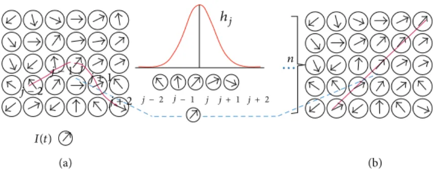
(a) (b) · · · ℎ𝑗 𝑛 𝑗 − 1𝑗 𝑗 − 2 𝑗 + 1 𝑗 + 2 𝐼(𝑡) 𝑗 − 2 𝑗 − 1 𝑗 𝑗 + 1 𝑗 + 2
Figure 1: Illustration of the training process. (a) Initial random state of the lattice. The input data vector is displayed here as𝐼(𝑡). Randomly
initialized network after a learning step; intermediate stage of self-organization. Best match is assigned as winning node. Updating the weight
allows the network to find its best matching nodes in the discrete output space (5). The nodes within the neighborhoodℎ𝑗learn from the
winning node. (b) Fully trained network after𝑛 iterations: Structured input space.
is reached by identifying the node that best matches the input𝐼, and this winning neuron 𝑃(𝐼) is found at a time step𝑡 by using the minimum-distance Euclidean criterion [4], where𝑛 is the total number of neurons in the network:
𝑃 (𝐼) = arg min
𝑗 𝐼 (𝑡) − 𝑤𝑗 , 𝑗 = 1, 2, . . . , 𝑛, (5)
where𝑤𝑗is the weight vector for the𝑗th node as ⃗𝑤𝑗 = [𝑤𝑗1, 𝑤𝑗2, . . . , 𝑤𝑗𝑚]𝑇. (6)
In SOFMAT, 𝑚 is defined as 6 corresponding to the number of diffusion gradient pulses (1). The first three elements of𝑤𝑗describe the position of𝑗th node, and the last three correspond to the orientation of the vector connecting the𝑗th node to the 𝑗 + 1st node.
SOFMAT identifies the winning neuron by computing a distance function comparing an input pattern𝐼 with the synaptic weight vectors,𝑤𝑗 for each node (5). The training process is illustrated inFigure 1. First, the weight vectors are mapped randomly onto a two-dimensional lattice.Figure 1(a) represents this initial random state of the lattice. Training of the network gives the closest match to the input data vector𝐼(𝑡) in the node (Figure 1(b)). The nodes within the neighborhoodℎ learn from the winning node (Figure 1(c)). The weight vectors within the neighborhoodℎ learn from the input data vector and get updated. InFigure 1(d), the final, fully trained network is displayed.
3.3. Cooperative Process in SOFMAT. Cooperation in SOM
algorithm is also inherited in SOFMAT. The level of coopera-tion of the neighborhood neurons is decided by the winning neuron (5).
(i) The topological neighborhoodℎ𝑗,𝑖is typically chosen as a Gaussian function [4]:
ℎ𝑗,𝑖(𝑥)(𝑡) = 𝑒(−𝑑2𝑗,𝑖/2𝜎2(𝑡)), (7)
𝜎 (𝑡) = 𝜎0𝑒(−𝑡/𝜏1), (8)
where 𝑟 is the sequential distance and 𝑑𝑖𝑗 is the Euclidean distance between the winning neuron𝑃(𝐼) and the other neurons(𝑗) in the string and calculated by the sequential distance𝑟 of 𝐼 and 𝑗 as given in the following:
𝑑2𝑗,𝑖= 𝑟 ( 𝑗) − 𝑟 (𝐼)2. (9) The width,𝜎(𝑛), of the Gaussian neighborhood function decreases for facilitating convergence at an exponential rate, and the neighborhood shrinks in each iteration. The depen-dence of𝜎 in discrete time 𝑡 (𝑡 = 0, 1, 2, . . .) in (8) contributes to the convergence of SOM learning algorithm by excluding more nodes from the neighborhood iteratively.𝜎0is the initial value of𝜎, and 𝜏1is the time constant, which are determined by ad hoc methods, influenced by the size of the input space and the number of output nodes as described in [5].
3.4. Adaptive Process in SOFMAT. For a given input pattern
𝐼, all the neurons in the vicinity of the winning neuron 𝑃(𝐼) are updated by a distance coefficient decreasing with the neighboring function,ℎ𝑗,𝑖. Note thatℎ𝑗,𝑖is 1 for the winning neuron and decreases exponentially as the nodes gets away from the winning neuron. The iterative learning process is actually representing the adaptation of the weight vectors towards an input pattern𝐼 and given as
⃗𝑤𝑗(𝑡 + 1) = ⃗𝑤𝑗(𝑡) + 𝜂 (𝑡) ℎ𝑗,𝑖(𝐼)(𝑡) (𝐼 − ⃗𝑤𝑗(𝑡)) . (10)
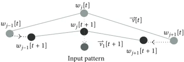
Equation (10) gives the computation of the updated weight vector𝑤𝑗(𝑡 + 1) at time 𝑡 + 1, with a time varying learning rate𝜂(𝑡), where 𝑤𝑗(𝑡) is the synaptic weight vector of neuron 𝑗 at time 𝑡 [4, 5]. As introduced in (4), our input space 𝐼 consists of the positional elements𝑥, 𝑦, and 𝑧 and directional elements 𝜆1, 𝜆2, and 𝜆3 for each voxel. The SOFMAT is shaped by comparing each input vector𝐼, to every node, in the neighborhood (Figure 1). The comparison is based on both position and orientation according to (5). Once the winning neuron is determined, the positions of the nodes are updated according to (10). The directional vectors of the SOFMAT nodes are updated according to the newly formed neuronal topology as in Figure 2. Assuming that nerve
Input pattern ⇀ ⇀ 1[𝑡 + 1] [𝑡] 𝑤𝑗−1[𝑡 + 1] 𝑤 𝑗+1[𝑡 + 1] 𝑤𝑗+1[𝑡] 𝑤𝑗[𝑡 + 1] 𝑤𝑗−1[𝑡] 𝑤𝑗[𝑡]
Figure 2: The pixel with the weight𝑤𝑗at time𝑡, nearest to the input
pixel, is winning and is moving towards this input pixel according
to (10) as shown with an arrow in the figure. Its neighbors,𝑤𝑗−1and
𝑤𝑗+1at time𝑡 on the string, are also moving to a lesser extent. The
update in the orientation can be recognized through initial weight
vector V[𝑡] and updated resulting vector V[𝑡 + 1]. Units close to
the winner as well as the winner itself have their weights updated significantly. Weights associated with far away output pixels do not change significantly. The update continues until the sought topology is found and the feature map is consistent.
tracts are formed from multiple axons, we provided multiple strings with an expectation to detect the underlying neuronal pathways. Multiple strings implementation methodology is summarized as follows:
SOFMAT with multiple strings:
(i) initially there are𝑁𝑦strings each of which is made of 𝑁𝑥nodes;
(ii) initial position and orientation of each node(𝑤) are randomly initialized;
(iii) for each node of the input pattern, 𝐼, the winning neuron is computed based on the minimization of the cost function as given in (5). The winning node also determines the winning string;
(iv) once the winning neuron and its string are deter-mined,
(a) a weight update matrix 𝑤𝑗(𝑡) is computed for that string using the position information according to (7), (8), and (10),
(b) the weight update matrix is computed for that string for updating the orientation information according to the new position as inFigure 2; (v) this procedure is repeated from step (iii) until the
maximum number of predefined iteration or conver-gence is reached;
(vi) the converging weight matrix that includes the posi-tion and orientaposi-tion informaposi-tion of the multiple strings is the resulting topology of SOFMAT. The aim of the implementation is to map the underlying topology of a discrete input space. Initially, the weights are assigned randomly and the SOM pattern is arbitrarily positioned. A starting input node is randomly picked among the inputs for training (Figure 2). The node with the closest reference vector represents the winning neuron𝑤𝑗(𝑡). At the iteration at discrete time 𝑡, the winning neuron 𝑤𝑗 moves towards the input pattern (Figure 2), and the two neighboring
neurons𝑤𝑗−1and𝑤𝑗+1in its Gaussian neighborhood move in smaller steps. The goal is to train the net until the topology is stable.
For each position update of a node the directional convergence of orientation vector is also achieved.
Following the three processes of the unsupervised learn-ing method, taklearn-ing into account both the position and the direction of a candidate node, SOFMAT enables the deter-mination of neural fiber tracts having similar diffusivity. The updated neighborhood helps to compute the proper neighbor of each winning neuron, which enables the algorithm to calculate the neural paths with respect to the underlying diffusivity.
3.5. Experimental Methods. The number of inputs is
deter-mined by the image dimensions, which is 150× 150 pixels in PISTE. The number of strings and the number of nodes in each string have been changed between 2–80 and 50–3200, respectively, for experimenting the convergence behavior of different PISTE topologies. The learning rate in (10) was set as 0.1, a typical rate for safe and stable convergence in the expense of slow learning and increased risk of local minima. Each individual PISTE pattern is examined for a number of iterations. For linear and linear break PISTE patterns, 500 iterations were sufficient. For the spiral trajectory the number of iterations was 6000 as expected. By varying iterations, the best match and the determination of the most reliable track is aimed. The more complex the investigated pattern becomes, the more iterations are needed. This is a natural characteristic of a self-organizing network. The main constraint here is the convergence. In each experiment the convergence is checked upon both the position and orientational training results. More detailed explanations and their discussions on exper-iments and their results are presented in Sections4and5.
The tracking results for SOFMAT are shown on four exemplary synthetic data sets. The PISTE trajectories described inSection 2.2were selected for the evaluation and comparison purposes when GTRACT and SLT methods were employed in the literature [11]. Both GTRACT and SLT are diffusion tensor fiber tracking suites like SOFMAT. The main difference is that these suites include streamline tracking tools. These fiber tracking methods include a guided tracking tool that integrates apriori information into a streamline algorithm. SOFMAT in contrast enables the tracking by detecting and following the orientation of the weighted neighbors. Especially the spiral trajectory which is known to be problematic for fiber tracking methods is also analyzed with SOFMAT. The reconstructed tracts are represented in the results section, overlaid on the T2 weighted MR images or fractional anisotropy (FA) maps of the reconstructed tract.
4. Results
4.1. Experimental Scenarios and Targets. In this study, the
linear, linear break, orthogonal crossing, and spiral PISTE data sets each of them with individual FA were examined with SOFMAT. Varying FA values give information about the anisotropy and as a result about the anatomy of the tissue investigated. A change in the FA map shows clues about
(a) (b) (c) 80 80 80 85 90 95100105 110 115 0 50 100 150 140 140 120 120 100 140 120 100 100 60 60 40 40 20 20
Figure 3: Linear PISTE trajectory. (a) T2 weighted image; (b) input corresponding to the computed eigenvectors (blue). Initial weights𝑤𝑗0
are seen in red. (c) Pink tracts on the T2 weighted image are SOFMAT’s implementation results.
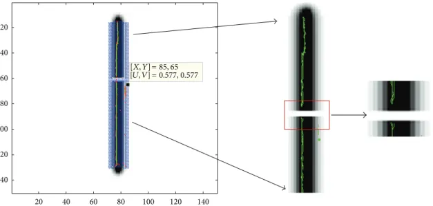
20 20 40 40 60 60 80 80 100 100 120 120 140 140 = 85, 65 = [𝑋, 𝑌] [𝑈, 𝑉] 0.577, 0.577
Figure 4: Linear break trajectory. Eigenvectors representing the diffusivity are superimposed on T2 image in blue. SOFMAT results with single string trial are seen in green (right). The gap in the middle of the tract is zoomed to give an idea about the implementation result of the algorithm.
the investigated trajectory. In PISTE, images are created on homogeneous anisotropic background, and decreasing anisotropy along tracts is applied. Therefore, the FA maps serve as filters where the routinely applied homogeneous ani-sotropic background can be extracted from the image. This process also acts as a noise removal highlighting the diffusion pattern. The eigensystem of𝐷 (2) is determined by principal component analysis (PCA) [1, 2, 12], and the principle diffusion direction is interpreted graphically in Figure 3. The entire DT resource is investigated with the proposed SOFMAT method. The search process of the pattern in the selected limits is completed in examining the eigenvectors of each pixel based on the predefined similarity measure. This examined dataset sample might be a whole image data or a single ROI. In this study, the trajectories are not separated into ROIs, they are examined on whole. The details of the investigated geometries are as follows.
Linear Trajectory with and without Break. The linear
tra-jectory is a straight-forward linear tract (Figure 3(a)). Its
background is homogenously anisotropic. One has a com-plete break at the tract (Figure 4). Along the length of the tract, its FA is linearly decreasing. The reconstructed tracts are plotted over the FA map of the investigated linear fiber trajectory (Figure 3). SOFMAT resolves the break on the linear break trajectory (Figures4and5), and it successfully calculates and reconstructs the tracts on the investigated fiber and not on the break (Figure 5).
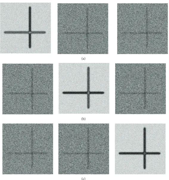
Orthogonal Crossing Trajectory. This PISTE trajectory is a
crossing sample of two fibers intersecting each other at a right angle. The FA values of each of these two orthogonal linear tracts have a slight difference as represented in the orthogonal elements in diffusion tensor image (Figure 6). In this simulated data, the difference on fibers with higher and lower FA values is observed. The SOFMAT results are evaluated with respect to their cost functions by means of spatial distance and angular similarity (Figure 8). SOFMAT reconstruction is displayed inFigure 7. Here, the network has converged with 40× 20 nodes in 500 iterations.
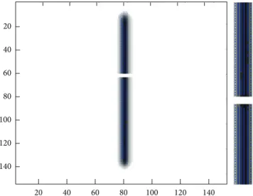
20 40 60 20 40 60 80 80 100 100 120 120 140 140
Figure 5: Linear break trajectory with multiple strings. SOFMAT results are seen in blue. The trajectory and the gap in the middle of it are determined by SOFMAT as represented.
Table 1: The tracking errors (in mm) of the three tracking tools for linear trajectory.
SLT GTRACT SOFMAT
SNR = 30 0.63 0.60 0.46
SNR = 15 0.90 0.65 0.48
SNR = 5 1.40 0.70 0.56
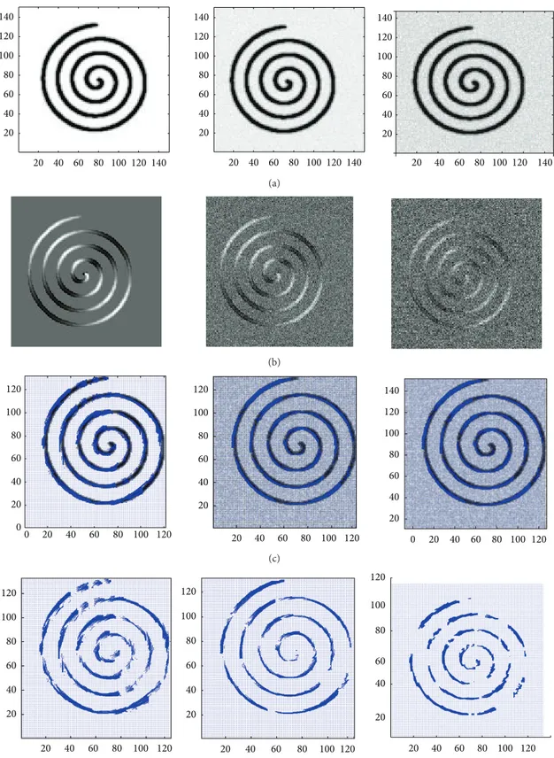
Spiral Trajectory. The spiral trajectory of PISTE is an in-plane
spiral tract overlaid on a homogenous isotropic background. It has a high FA value. Here, not only the noise-free sample is investigated by SOFMAT but also the curvy trajectory is examined for SNR values of 30 and 15. Spiral tracts are especially problematic for streamline tractography [1, 13] because curvy trajectory cannot be reconstructed accurately by this method. So it is not able to follow the relatively high curvature of the fiber. SOFMAT, however, has the ability to follow the curvature (Table 3). The reconstruction results are presented inFigure 9.
The proposed SOFMAT algorithm is compared with the two well-known fiber tracking suits, GTRACT [11] and SLT [1] using PISTE dataset as a benchmark. The tracking results for the three algorithms were compared qualitatively and quantitatively. As indicated in the reference papers [18,19], the error in fiber tracking is proportional to the square root of the distance along the track. The evaluation of GTRACT algorithm [11] has been performed regarding the predefined error definition as in [18, 19]. Also in this work, the error is computed based on distance measure as in the definition in the literature. In GTRACT [11], the tracking error was accessed on the linear trajectory and the orthogonal crossing trajectory. For that reason, error of SOFMAT is computed for the two phantom trajectories, the linear and the orthogonal crossing, and computation results are presented in Tables1
and 2. Results indicate that SOFMAT gives promising and relatively superior results compared to SLT and GTRACT
Table 2: The tracking errors (in mm) of the three tracking tools for orthogonal crossing trajectory.
SLT GTRACT SOFMAT
SNR = 30 0.675 0.65 0.46
SNR = 15 0.875 0.66 0.48
SNR = 5 1.45 0.70 0.65
Table 3: The mean tracking errors (in mm) of SOFMAT reconstruc-tion of spiral trajectory.
SOFMAT Spatial Angular Noise free 0.699 0.1151 SNR = 30 0.743 0.1127 SNR = 15 1.611 0.3416 SNR = 5 6.298 0.5087
results. SOFMAT has the ability to generate complex tracts. Aside from the linear, linear break, and orthocrossing trajec-tories mentioned in [11], spiral trajectory is also investigated in this study (Figure 9;Table 3).
The results for all the three tracking tools are represented in Tables1and2 for all the existing linear and orthogonal PISTE trajectories, respectively. The mean tracking errors in SLT, GTRACT, and SOFMAT for linear PISTE trajectory with an SNR of 30 are 0.63 mm, 0.60 mm, and 0.46 mm, respectively (Table 1). With an SNR of 5, again for the linear trajectory, the tracking errors for SLT, GTRACT, and SOFMAT are 1.40 mm, 0.70 mm, and 0.56 mm, respectively (Table 1). The mean tracking errors in SLT, GTRACT, and SOFMAT for orthogonal crossing phantom with an SNR of 30 are 0.675 mm, 0.65 mm, and 0.46 mm, respectively (Table 2). The mean tracking error in SLT and GTRACT for orthogonal crossing phantom (SNR = 5) are 1.45 and 0.7 mm, respectively. SOFMAT’s tracking error for SNR = 5 for orthocrossing phantom is 0.65 mm (Table 2). Here, the SOFMAT parameters 𝑁𝑥 and 𝑁𝑦 are in each experiment 80 and 40, respectively. The parameters are assigned based on the network’s convergence status. The updated network parameters are given in detail inTable 6.
To observe the effectiveness of the ANN based algorithm, the convergence of the cost function is detected as SOFMAT weights are stabilized. The SOFMAT tracking results of an uncertainty region, namely, an orthocrossing trajectory, are also presented inFigure 7.
In all examinations, the input pattern is the T2 weighted image of spiral trajectory with input matrix size of 150× 150. In order to compare SOFMAT’s results, the network in all of the three cases has 50 strings, where the number of iterations is 6000 and unique in all three exams.
For each of the investigated trajectory, the network’s parameters are methodically and carefully determined. The determination of parameters effect the phases of the network and its ability to converge safe and stably. As mentioned previously, each individual PISTE pattern is examined for a number of iterations. The aim of varying iterations is to find
(a)
(b)
(c)
Figure 6: Diffusion tensor representation of the orthogonal PISTE trajectory. The different diffusivities for this geometry are seen on the
diagonal images. Upper left:𝐷𝑥𝑥—the anisotropy of 𝐷 in 𝑥 direction and in the middle: 𝐷𝑦𝑦—the anisotropy of 𝐷 in 𝑦 direction.
the best match and so to determine the most reliable tract. The more the investigated pattern gets complex, iteration number increases. This also explains why the spiral trajectory’s itera-tion number (=6000) was the highest among all the trajecto-ries. This is a natural characteristic of a self-organizing net-work.
In each experiment, the convergence is checked upon both the position and orientational training results. Here, the orthogonal crossing trajectory with 150× 150 original input size is selected as a sample. In Tables4–6, various network parameter selections and their results are represented. First, a network with 2 strings created from 50 to 200 nodes is analyzed. The mean spatial distance between the known val-ues of the input pattern and those calculated with SOFMAT as output vary from 5.7429 to 1.819 pixels. In all of these cases, the iteration number is kept constant with 500 steps. As expected, with increased number of strings, the trajectory is more precisely determined (Table 6).
Table 4: The validation results of the SOFMAT implementation. The orthogonal crossing trajectory is selected as sample. Here, analysis results for 2-string case are shown.
Node× string
𝑁𝑥× 𝑁𝑦 Mean spatial distance Angular norm
50× 2 5.7429 0.1206
100× 2 3.5785 0.0999
150× 2 2.2843 0.1003
200× 2 1.8195 0.0965
5. Discussion
Several studies aim to investigate the synchronization, infor-mation transmission, and signal sensitivity in concept of the-oretical neuroscience using neural networks [20–23]. There are studies which concentrate on the synchronization on
20 40 60 80 100 120 140 20 40 60 80 100 120 140
Figure 7: The SOFMAT result superimposed on T2 images for orthogonal crossing trajectory. The tracts are defined along the paths through the total trajectory. Both of the orthogonal tracts are reconstructed completely.
Table 5: The validation results of the SOFMAT implementation for orthogonal crossing. A wider network for orthogonal crossing trajectory is investigated and represented.
Node× string
𝑁𝑥× 𝑁𝑦 Mean spatial distance Angular norm
20× 20 8.17 0.0923
25× 20 3.3412 0.0943
30× 20 2.8286 0.0883
40× 20 2.1506 0.0910
60× 20 1.7862 0.0917
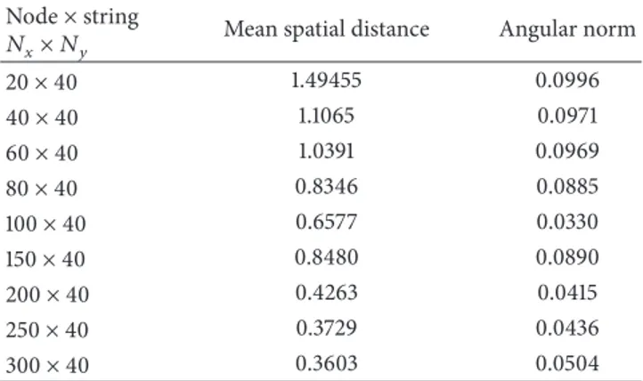
Table 6: The validation results of the SOFMAT implementation for orthogonal crossing with updated network parameters.
Node× string
𝑁𝑥× 𝑁𝑦 Mean spatial distance Angular norm
20× 40 1.49455 0.0996 40× 40 1.1065 0.0971 60× 40 1.0391 0.0969 80× 40 0.8346 0.0885 100× 40 0.6577 0.0330 150× 40 0.8480 0.0890 200× 40 0.4263 0.0415 250× 40 0.3729 0.0436 300× 40 0.3603 0.0504
scale-free neuronal networks with phase-repulsive coupling and delay [20–23]. These studies focus on the dependency of synchronization transitions on the information transmission delay over scale-free neuronal networks with attractive or repulsive coupling [24]. Other than biological neuronal stud-ies, our study aims to explore the structural fiber tractography to define the brain fiber paths properly using artificial neural networks. To analyze the complex dynamics of the biological
neuronal networks such as excitability delay and complex topologies, it is adequate to develop additional theoretical and experimental studies.
Unlike the functional magnetic resonance imaging (fMRI), DTI highlights the anatomical connectivity patterns of the brain and does not include any information about the function of the brain activity directly. Generally, clinical DTI studies measure the data voxel wise where the size of each voxel is on the order of millimeters. But it’s well-known that there are millions of fibers passing through each image voxel. Thus, the spatiotemporal dynamics within a voxel can be explored by using the Hudgkin-Huxley neuronal networks [24,25]. In the concept of our paper, the anatomical relation-ship and connectivity are tried to be estimated among the voxels. The mathematical model that is proposed in [24] can be modified and optimized for the voxel DTI data to deduce the anatomical connectivity in the brain. It may hold signi-ficant value for future brain imaging studies.
Our study proposes an artificial neural network approach named SOFMAT based on self-organizing feature mapping to generate simulated tracts based on their diffusivity and to clarify, especially, the fiber tracts in complex fiber architec-tures. The artificial neuronal topology based on unsupervised learning method is used as a classifier to identify the struc-tured simulated topologies.
Mapping the brain’s white matter noninvasively is possi-ble through proper analysis of DTMR images. The algorithms proposed for fiber mapping and fiber tractography are to be examined by synthetically simulated datasets for accurate validation. In this study, a common synthetic DT dataset, namely, PISTE, which is specially generated for verification purposes of DT and tractography algorithms, is used for verification and validation. One of the main constraints in the accuracy of the mapping results is the determination of intersecting fiber tracts in uncertainty regions. In DTI literature these intersecting regions generate a critical track-ing problem. Providtrack-ing a solution for identification of the orientations of the brain fibers in these uncertainty regions in diffusion tensor analysis is of great importance [26, 27]. Methods and updates are to be researched to define these uncertainty regions. Streamline tractography (SLT) is recalled as an accepted basis method for diffusion tensor tractography (DTT). For that reason, SLT is one of the algorithms selected for comparison with SOFMAT (Tables1and2). Secondary, the DTT algorithm chosen for evaluation is the GTRACT software implementation. The SLT uses the principle eigen-vector,𝑒1, to compute Euler’s method approximation to the parameterized tract [1,13].
In this study, we proposed a tracking tool for detecting real brain fibers later as a future study according to unsuper-vised learning method SOFM. The main idea of SOFMAT is to track the complex fibers according to unsupervised learning while keeping the structural information of the underlying tissue. The methodology is applied and examined firstly on computer simulated trajectories PISTE for verifica-tion and validaverifica-tion of the algorithm.
The proposed fiber reconstruction method SOFMAT clarifies the diffusivities in the previously mentioned uncer-tainty regions (Figures3,5, and9). Quantitative results are
Noise free 1200 1000 800 600 400 200 0 0
Mean spatial distance (pixel)
1 2 3 4 5 6 7 8 9 10 𝑁𝑋 ×𝑁 𝑌 Mean-8.35𝑒 − 01 Std deviation-9.87𝑒 − 01 (a) 1200 1000 800 600 400 200 0 0
Mean spatial distance (pixel)
1 2 3 4 5 6 7 8 9 10 SNR = 7 𝑁𝑋 ×𝑁 𝑌 Mean-9.13𝑒 − 01 Std deviation-1.89𝑒 + 00 (b)
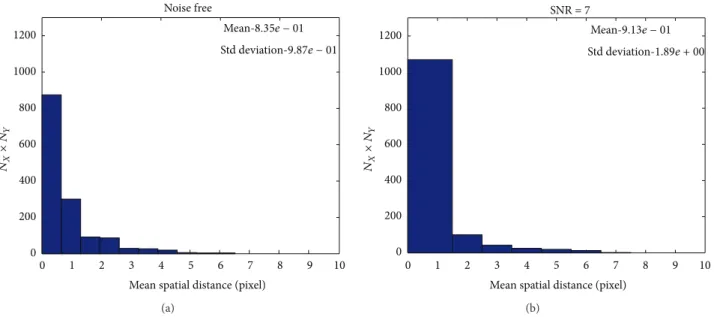
Figure 8: The SOFMAT results are investigated, and the determined neighborhood’s coordinates and their related calculated eigenvectors are evaluated. The histogram shows the similarity of the original input and the SOFMAT’s reconstructed tract for orthocrossing trajectory: noise free (a) and SNR = 5 (b). The angular cost function results inform that the input and the output are nearly the same. Here, the input
pattern is 150× 150, where in both cases noise free and SNR = 5, the parameters 𝑁𝑥and𝑁𝑦are 80 and 40, respectively.
listed in Tables1and2with respect to well accepted tracto-graphy techniques [1,11,13]. These results are relatively sup-erior to the results of SLT and GTRACT. The figures in the result section are represented to give an idea of how (well) the SOFMAT results match the input patterns. The method is tested with varying SNR values and also in low anisotropy regions. Low anisotropy regions are studied more intensely focusing on the problematic crossings on the phantoms. The fractional anisotropy (max. FA = 1) represents the degree of anisotropy, in other words the deviation from isotropic diffu-sion (FA= 0). The grey matter in the brain is nearly isotropic (0.37 > FA > 0.15). In uncertainty regions, it is hard to define the direction of the fiber tracts. Therefore, the detection of fib-ers in regions having low fractional anisotropy is an advan-tage of the proposed method. Because in real brain studies, aside from grey matter, low anisotropy regions are uncer-tainty areas or injured regions. Therefore, the ability to recon-struct the fiber recon-structures in low anisotropy regions is an important benefit of SOFMAT. Optimizing the cost function and neuron selection, the algorithm is able to detect small tract changes and curvy trajectories (Figure 9andTable 3).
Fiber tracking in SOFMAT begins by identifying seed voxels to be used as potential starting positions for the recon-structed fibers. Based on the predetermined eigensystem of the sample trajectories, fiber tract is estimated within each voxel regarding to the diffusivity defined by this eigensystem. Here, the knowledge in diffusion literature suggests that the eigensystem defines the diffusivity [1,13]. Each node (neuron) in the region of interest (ROI) is considered as part of a potential fiber tract. The computed winning neurons define the possible nerve tract a fiber can follow with respect to both the coordinate and the directional information of the winning neurons. In other words, a winning neuron determines the
newly gained voxel to the tract in terms of its coordinate and direction. The estimation follows by evaluating each node’s neighboring function in terms of the similarity criteria.
The novel algorithm SOFMAT is being evaluated throughout the study. The validation study performed on PISTE gives promising results, and they have been compared to the well-known SLT method and the GTRACT algorithm. In the literature, as it has been represented in [11] by GTRACT evaluation, the error is investigated along the resulting tract, and quantitative results are given in Tables1and2. SOFMAT is able to handle fiber crossings and also the spiral trajec-tory. SOFMAT results to highlight to propagation of fibers through the intersecting and curvy regions are represented in Figures3,4,5,7, and9. The minimization of the error is suc-cessfully managed where the characteristics can be tracked in related cost function of the network. The increasing num-ber of neurons and iterations selected in the SOM imple-mentation results more reliable tractography outputs (Tables
4,5, and6).
Investigating samples with both varying noise and differ-ent geometry is important for evaluation, because the devia-tion from the original fiber path is caused mainly by the noise. The relationship between the tracking error to SNR is acceptable in all examinations. Also dependency on the geo-metry is seen (Figures3and9). Considering that every tra-jectory in PISTE has a different diffusivity characteristics, it is meaningful that the cost functions representing the fiber determination performance for linear and orthocrossing geo-metries vary from each other. The SOFMAT algorithm improves the performance of the fiber tracking even in the presence of noise discussed in Tables1and2. SOFMAT also allows tracking branching fibers. In conclusion, SOFMAT is able to describe two or more fiber tracts simultaneously and
140 120 100 80 60 40 20 20 40 60 80 100 120 140 140 120 100 80 60 40 20 20 40 60 80 100 120 140 140 120 100 80 60 40 20 20 40 60 80 100 120 140 (a) (b) 120 120 100 100 80 80 60 60 40 40 20 120 100 80 60 40 20 0 0 20 40 60 80 100 120 20 0 20 40 60 80 100 120 140 120 100 80 60 40 20 (c) 120 120 120 100 100 100 80 80 80 60 60 60 40 40 40 20 20 20 20 40 60 80 100 120 120 100 80 60 40 20 120 100 80 60 40 20 (d)
Figure 9: The spiral trajectory results are represented. (a): T2 weighted images; from left to right: noise free T2; SNR = 30; SNR = 15. (b): FA images of each input data. (c): SOFMAT results superimposed on respective T2 weighted images. (d): SOFMAT reconstructions exclusively.
to reconstruct tracts in uncertainty regions. SOFMAT, on the other hand, does not lose the fiber tractography in relatively high SNRs.
The SOFMAT method gives promising results, compared to the traditionally implemented and well-accepted tractog-raphy algorithms mentioned above (Tables 1 and 2). As a future work we plan to implement SOFMAT on real brain.
6. Conclusion
This paper represents a novel approach namely self-organiz-ing feature mappself-organiz-ing tractography (SOFMAT) for complex fiber tracking purposes in diffusion tensor analysis. The algo-rithm is based on unsupervised learning in artificial neural networks. As an alternative to the existing methods, SOF-MAT is also effective in low anisotropy regions and less affected to noise and curvature complexity than GTRACT and SLT methods. Also, unlike some DTT studies established with PISTE [28,29], the presented SOFMAT study provides performance evaluation other than just visual inspection. The error analysis of the SOFMAT results compared to the exist-ing methods gives improved tract determination and follow-up. In crossing regions with intersecting fiber distributions and varying SNR values, SOFMAT is able to define the pre-determined fiber paths successfully with a standard deviation of (0.8–1.9)× 10−3depending on the trajectory and the SNR value selected. The results illustrate the capability of SOFMAT to reconstruct complex fiber tract configurations.
Conflict of Interests
The authors have no conflict of interests to disclose.
Acknowledgment
This work is supported in part by Bogazici University Scien-tific Research Project no. 07HX104D.
References
[1] P. J. Basser, S. Pajevic, C. Pierpaoli, J. Duda, and A. Aldroubi, “In
vivo fiber tractography using DT-MRI data,” Magnetic Reson-ance in Medicine, vol. 44, pp. 625–632, 2000.
[2] D. Le Bihan, J. F. Mangin, C. Poupon et al., “Diffusion tensor imaging: concepts and applications,” Journal of Magnetic
Reso-nance Imaging, vol. 13, no. 4, pp. 534–546, 2001.
[3] H. Johansen-Berg and T. E. J. Behrens, “Just pretty pictures? What diffusion tractography can add in clinical neuroscience,”
Current Opinion in Neurology, vol. 19, no. 4, pp. 379–385, 2006.
[4] S. Haykin, Neural Networks: A Comprehensive Foundation, Pre-ntice-Hall, Upper Saddle River, NJ, USA, 2005.
[5] T. Kohonen, Self-Organizing Maps, Springer, Berlin, Germany, 2001.
[6] X. Wang, F. Kang, J. Li, and X. Wang, “Inverse parametric ana-lysis of seismic permanent deformation for earth-rockfill dams using artificial neural networks,” Mathematical Problems in
Engineering, vol. 2012, Article ID 383749, 19 pages, 2012.
[7] C. Yao, X. Gao, and Y. Yu, “Wind speed forecasting by wavelet neural networks: a comparative study,” Mathematical Problems
in Engineering, vol. 2013, Article ID 395815, 7 pages, 2013.
[8] C. Ding, W. Wang, X. Wang, and M. Baumann, “A neural net-work model for driver’s lane-changing trajectory prediction in Urban traffic flow,” Mathematical Problems in Engineering, vol. 2013, Article ID 967358, 8 pages, 2013.
[9] I. Lou and Y. Zhao, “Sludge bulking prediction using principle component regression and artificial neural network,”
Mathe-matical Problems in Engineering, vol. 2012, Article ID 237693,
17 pages, 2012.
[10] F. Sedaghati, A. Nahavandi, M. A. Badamchizadeh, S. Ghaemi, and M. A. Fallah, “PV maximum power-point tracking by using artificial neural network,” Mathematical Problems in
Engineer-ing, vol. 2012, Article ID 506709, 10 pages, 2012.
[11] P. Cheng, V. A. Magnotta, D. Wu et al., “Evaluation of the GTRACT diffusion tensor tractography algorithm: a validation and reliability study,” NeuroImage, vol. 31, no. 3, pp. 1075–1085, 2006.
[12] R. Watts, C. Liston, S. Niogi, and A. M. Uluˇg, “Fiber tracking using magnetic resonance diffusion tensor imaging and its applications to human brain development,” Mental Retardation
and Developmental Disabilities Research Reviews, vol. 9, no. 3,
pp. 168–177, 2003.
[13] S. Mori, B. J. Crain, V. P. Chacko, and P. C. M. van Zijl, “Three-dimensional tracking of axonal projections in the brain by mag-netic resonance imaging,” Annals of Neurology, vol. 45, pp. 265– 269, 1999.
[14] D. K. Jones, M. A. Horsfield, and A. Simmons, “Optimal stra-tegies for measuring diffusion in anisotropic systems by mag-netic resonance imaging,” Magmag-netic Resonance in Medicine, vol. 42, pp. 515–525, 1999.
[15] D. K. Jones, A. Simmons, S. C. R. Williams, and M. A. Horsfield, “Non-invasive assessment of axonal fiber connectivity in the human brain via diffusion tensor MRI,” Magnetic Resonance in
Medicine, vol. 42, pp. 37–41, 1999.
[16] S. C. Deoni and D. K. Jones, “Generation of a common diffu-sion tensor imaging dataset,” in Proceedings of the ISMRM
Workshop on Methods for Quantitative Diffusion Methods for Quantitative Diffusion MRI of Human Brain, 2005, http:// cubric.psych.cf.ac.uk/commondti.
[17] M. Spratling and G. M. Hayes, “A self-organising neural net-work for modelling cortical development,” in Proceedings of
European Symposium on Artificial Neural Networks (ESANN ’98), pp. 333–338, 1998.
[18] N. F. Lori, E. Akbudak, J. S. Shimony et al., “Diffusion tensor fiber tracking of human brain connectivity: aquisition methods, reliability analysis and biological results,” NMR in Biomedicine, vol. 15, no. 7-8, pp. 494–515, 2002.
[19] M. Lazar and A. L. Alexander, “White matter tractography using diffusion tensor deflection,” Human Brain Mapping, vol. 18, no. 4, pp. 306–321, 2003.
[20] Q. Wang, M. Perc, Z. Duan, and G. Chen, “Synchronization transitions on scale-free neuronal networks due to finite infor-mation transmission delays,” Physical Review E, vol. 80, no. 2, Article ID 026206, 2009.
[21] Q. Wang, G. Chen, and M. Perc, “Synchronous bursts on scale-free neuronal networks with attractive and repulsive coupling,”
PLoS ONE, vol. 6, no. 1, Article ID e15851, 2011.
[22] Q. Wang and G. Chen, “Delay-induced intermittent transition of synchronization in neuronal networks with hybrid synapses,”
[23] Q. Wang, H. Zhang, and G. Chen, “Effect of the heterogeneous neuron and information transmission delay on stochastic reso-nance of neuronal networks,” Chaos, vol. 22, Article ID 043123, 7 pages, 2012.
[24] Q. Wang, M. Perc, Z. Duan, and G. Chen, “Delay-enhanced coherence of spiral waves in noisy Hodgkin-Huxley neuronal networks,” Physics Letters A, vol. 372, pp. 5681–5687, 2008. [25] Q. Wang and Y. Zheng, “Effects of information transmission
delay and channel blocking on synchronization in scale-free Hodgkin-Huxley neuronal networks,” Acta Mechanica Sinica, vol. 27, no. 6, pp. 1052–1058, 2011.
[26] P. J. Basser, J. Mattiello, and D. LeBihan, “MR diffusion tensor spectroscopy and imaging,” Biophysical Journal, vol. 66, no. 1, pp. 259–267, 1994.
[27] D. LeBihan, C. Poupon, A. Amadon, and F. Lethimonnier, “Arti-facts and pitfalls in diffusion MRI,” Journal of Magnetic
Reso-nance Imaging, vol. 24, pp. 478–488, 2006.
[28] C. Qin, N. Kang, and N. Cao, “Performance evaluation of aniso-tropic diffusion simulation based tractography on phantom images,” in Proceedings of the 45th Annual ACM Southeast
Con-ference (ACMSE ’07), pp. 521–522, New York, NY, USA, July
2007.
[29] S. C. Mang, D. Logashenko, D. Gembris, G. Wittum, W. Grodd, and U. Klose, “Diffusion simulation-based fiber tracking using time-of-arrival maps: a comparison with standard methods,”
Magnetic Resonance Materials in Physics, Biology and Medicine,
Submit your manuscripts at
http://www.hindawi.com
Hindawi Publishing Corporation
http://www.hindawi.com Volume 2014
Mathematics
Journal ofHindawi Publishing Corporation
http://www.hindawi.com Volume 2014 Mathematical Problems in Engineering
Hindawi Publishing Corporation http://www.hindawi.com
Differential Equations
International Journal of
Volume 2014
Hindawi Publishing Corporation
http://www.hindawi.com Volume 2014 Mathematical PhysicsAdvances in
Complex Analysis
Journal ofHindawi Publishing Corporation
http://www.hindawi.com Volume 2014
Optimization
Journal ofHindawi Publishing Corporation
http://www.hindawi.com Volume 2014
Combinatorics
Hindawi Publishing Corporation
http://www.hindawi.com Volume 2014
International Journal of
Journal of Hindawi Publishing Corporation
http://www.hindawi.com Volume 2014
Function Spaces
Abstract and Applied Analysis
Hindawi Publishing Corporation
http://www.hindawi.com Volume 2014 International Journal of Mathematics and Mathematical Sciences
Hindawi Publishing Corporation http://www.hindawi.com Volume 2014
The Scientific
World Journal
Hindawi Publishing Corporation
http://www.hindawi.com Volume 2014
Discrete Dynamics in Nature and Society Hindawi Publishing Corporation
http://www.hindawi.com Volume 2014
Discrete Mathematics
Journal ofHindawi Publishing Corporation
http://www.hindawi.com Volume 2014 Hindawi Publishing Corporationhttp://www.hindawi.com Volume 2014