New Generation Computing, 10 (1992) 287-313 OHMSHA, LTD. and Springer-Verlag
9 OHMSHA, LTD. 1992
Highly Parallel Execution of Production Systems:
A Model, Algorithms and Architecture*
K e m a l O F L A Z E R
Department of Computer Engineering and Information Sciences, Bilkent University,
Bilkent, Ankara, 06533 Turkey.
Received 15 October 1990
Final manuscript received 28 October 1991
Abstract
This paper presents a new parallel processing scheme called D Y N A M I C - J O I N for OPS5-1ike production systems along with associated parallel algorithms, a parallel architecture and simulation results from a number o f production systems. The main motivation behind D Y N A M I C - J O I N is to reduce the variations in the processing time require- ments and improve limited production level parallelism. For this, the model employs some redundancy that allows the processing o f a production to be divided into units of small granularity each o f which can be processed in parallel. As a consequence in addition to production level parallelism where a set of relevant productions are processed in parallel, a second level of parallelism can be exploited.After a detailed description of the model proposed, the paper presents algorithms for processing productions with D Y N A M I C - J O I N , along with a discussion o f various issues and possible disadvantages. Subsequently, the paper presents a parallel processor architecture that can implement D Y N A M I C - J O I N , along with simulation results from real production systems.
Keywords: Production Systems, Parallel Processing, Massively Parallel Architec- tures.
This work was done as a part of the author's doctoral thesis at Carnegie Mellon University, Pittsburgh, PA 15213, U.S.A. It was supported in part by the Defense Advanced Research Projects Agency (DoD), ARPA Order No. 3597, monitored by the Air Force Avionics Laboratory under Contract F33615-81-K-1539. The views and conclusions contained in this document are those of the author and should not be interpreted as representing the official policies, either expressed or implied, of the Defense Advanced Research Projects Agency, or the United States Government.
288 K. Oflazer
w
Introduction
This paper presents a new parallel processing method called D Y N A M I C - J O I N , associated parallel algorithms and a parallel architecture along with simulation results, for OPS5-1ike p r o d u c t i o n systems. The main motivation behind D Y N A M I C - J O I N is to reduce the variations in the process- ing time requirements and hence improve limited p r o d u c t i o n level parallelism. F o r this, the model employs some redundancy that allows the processing o f a p r o d u c t i o n to be divided into units of small granularity each of which can be processed in parallel. As a consequence, in addition to production level parallel- ism where a set of relevant productions are processed in parallel, a second level of parallelism can be exploited.
After an overview o f parallelism in p r o d u c t i o n systems, the paper first presents a detailed description o f the D Y N A M I C - J O I N data and processing model. Subsequently, the paper presents a parallel processor architecture for implementing implement D Y N A M I C - J O I N . Results on the run-time behavior o f the algorithm and the performance o f the parallel processor obtained from a n u m b e r o f large production systems like R1, X S E L are presented.
w Production Systems
Production systems are general computational mechanisms that have been employed as a programming paradigm in artificial intelligence where computation proceeds by applying rules in a sequence determined by the data a n d / o r goals. They have been a paradigm o f choice for building a class o f programs known as expert systems. A production system consists of a set o f
rules called productions that make up the production memory and a global database called the working memory. In general, a production is a statement o f the form:
P: C~C2...C~ ---> AIAz...A~
where C1 through Cc are c o n d i t i o n s - c a l l e d the left hand side or the antecedents and A~ through Aa are actions--called the right hand side or the consequents. C o n d i t i o n s are partially specified patterns to be evaluated on the current state o f the working memory. Actions are executed when all the conditions o f a p r o d u c t i o n are satisfied and the production is selected for firing. The actions o f the firing rule modify the contents of the database, enabling other productions for execution. The production system interpreter is the underlying mechanism that determines which productions are satisfied with the current sate o f the working memory and should be executed. In general, the interpreter for a p r o d u c t i o n system executes productions in a recognize-act cycle. Since the OPS5 system ~) will be used t h r o u g h o u t the paper, its recognize-act cycle will be outlined here. The OPS5 interpreter goes through the following phases in the recognize-act cycle:
Highly Parallel Execution of Production Systems: A Model, Algorithms and Architecture 2 8 9 M A T C H : The L H S conditions of the productions in PM are evaluated to determine which productions are satisfied with the current state o f the working memory.
C O N F L I C T R E S O L U T I O N : One of the productions from the set o f matching production--conflict s e t - i s selected for execution.
ACT: The actions specified in the RHS o f the selected production are performed. The working memory actions (i.e., make, remove, and modify) modify the state o f the working memory. Other actions may perform i n p u t / o u t p u t or any other computation.
Forgy ~) has observed that production system interpreters typically spend more than 90% o f their time in the match phase and hence any significant speed-up in the execution o f production systems will result from exploiting and improving any parallelism in the match process.* Match essentially involves finding which o f the productions in the production memory are satisfied with the WMEs in the working memory. Forgy 3) has noted the slow rate o f change o f the working memory and has suggested that saving match state across cycles saves a considerable a m o u n t o f computation. Thus match becomes an in- cremental computation where only the changes to working memory are matched to the productions and to any state associated with productions accumulated during previous match cycles.
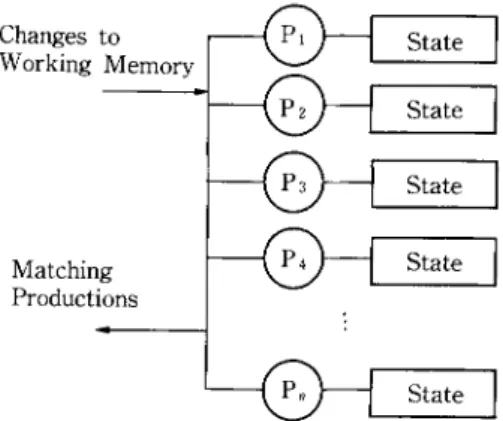
The state o f a p r o d u c t i o n is that portion o f the current working memory that is relevant to the condition elements of that production, and some other auxiliary information regarding how the working memory elements are j o i n e d together to form partial or complete instantiations. Figure 1 presents a simple view o f the computation model that is employed in an interpreter that keeps a state associated with each production. With this model, the match process has
Changes to Working Memory Matching Productions State ] ~ ~ State State State State Fig. 1 Computation model with production states.
However very recent progress in building special optimized (uniprocessor) compilers has been effective and has reduced this number down to around 50% ~~ and this indicates that improve- ment efforts should start considering other phases of production system execution.
290 K. Ofla~r two phases: (1) Selection where productions whose states will be affected as a result o f the action are determined.* (2) Production State Update where states o f the productions that are selected by the selection are updated. If any of the p r o d u c t i o n s are fully satisfied, they are inserted into the conflict set for conflict resolution.
2 . 1 Parallelism in Production Systems
Superficially, p r o d u c t i o n systems appear to manifest a very high degree o f parallelism. Productions, being independent of each other, can all be processed in parallel in response to change to the working memory. However, it is likely that as a result o f a working m e m o r y action, only a small number o f p r o d u c t i o n s will be affected. One can intuitively speculate on this by noting that most p r o d u c t i o n systems are c o m p o s e d of a large n u m b e r o f small modules, each o f which w o r k on some aspect o f the problem. The p r o d u c t i o n s in one module are designed to influence p r o d u c t i o n s either in the same m o d u l e or in other m o d u l e s with which that module interacts. Hence when a p r o d u c t i o n ' s action modifies the w o r k i n g m e m o r y by inserting or deleting a w o r k i n g m e m o r y element (WME), only a few out of the large n u m b e r of p r o d u c t i o n s need to be processed. It is this small subset o f the p r o d u c t i o n s that needs to be processed in order to the determine the contents o f the conflict set, instead o f the complete set o f productions.
Exploiting p r o d u c t i o n level parallelism involves processing the p r o d u c - tions that are affected by a change to the working m e m o r y in parallel. G u p t a ' s measurements 4~ and our analyses indicate that for most o f the p r o d u c t i o n systems, on the average 20 to 30 productions need to be processed as a result o f a change to the working m e m o r y although there are exceptions to this. However, the a m o u n t o f work involved in processing each p r o d u c t i o n may vary consider- ably. T h i s reduces the parallelism at the production level since the time a match cycle takes is determined by the production which takes the longest time to be processed. So if one had a large number o f p r o c e s s o r s - o n e to a production at the e x t r e m e - m o s t of them w o u l d be idle either having no work to do, or waiting for some other processor to finish.
G u p t a has investigated other levels of parallelism that can be extracted from the uniprocessor OPS5 R E T E interpreter a n d has incorporated these sources o f parallelism into an interpreter for shared m e m o r y multiprocessor systemsJ '6's~ Further lower level parallelism at a finer level of granularity is also potentially available. F o r example, Stolfo 14'16) presents a massively parallel machine, D A D O , for parallel processing o f p r o d u c t i o n systems. Miranker 8'9) has devised a match algorithm for D A D O which is d y n a m i c variant of R E T E . Similarly Hillyer and Shaw 7) present a scheme for using a massively parallel m a c h i n e N O N - V O N to e m p l o y associative processing for exploiting lower level 9 A production is affected by a working memory transaction, when the WME inserted or deleted
Highly Parallel Execution of Production Systems: A Model, Algorithms and Architecture 291 parallelism in pattern and variable m a t c h i n g o p e r a t i o n s o f the R E T E inter- preter. Schreiner and Z i m m e r m a n n 13) have reported a system which consists o f a data-driven pipeline o f special-purpose processing elements. T h e y r e p o r t rather high execution rates b u t the systems they simulate have a very small n u m b e r o f p r o d u c t i o n s ( a r o u n d 10) w h i c h is n o t realistic. Perlin 12) has presented a m a t h e m a t i c a l f r a m e w o r k f o r an incremental m a t c h i n g a l g o r i t h m for determin- ing the tuple instantiations o f f o r w a r d c h a i n i n g p r o d u c t i o n rules a n d it is c l a i m e d that the match o p e r a t i o n can be p e r f o r m e d in constant time p r o v i d e d sufficient n u m b e r o f processors are available. This f o r m u l a t i o n h o w e v e r relies substantially on the fact t h a t the d o m a i n s o f all possible values for variables used in i n t e r c o n d i t i o n m a t c h i n g are k n o w n b e f o r e h a n d which is a l m o s t never possible.
w
Processing the State of a Production
State processing is by far the d o m i n a n t c o m p o n e n t in match. N a t u r a l l y , there are a n u m b e r o f ways o f h o w state processing can be implemented, e a c h m a i n t a i n i n g some intermediate i n f o r m a t i o n in some f o r m or the other. F o r example, R E T E 3) m a i n t a i n s o n l y the i n d i v i d u a l c o n d i t i o n element m e m o r i e s ( a - m e m o r i e s ) as W M E s are inserted or deleted until some W M E matches the first c o n d i t i o n element o f the p r o d u c t i o n . At this p o i n t , it starts j o i n i n g t h e m in a fixed sequence until no further j o i n s are possible. A s s u m i n g R1 ... Rc d e n o t e the a - m e m o r i e s o f the c o n d i t i o n s o f a p r o d u c t i o n w i t h c conditions, the infor- m a t i o n kept by R E T E for a p r o d u c t i o n is:*
R~ ... Re, as the c o n d i t i o n element m e m o r i e s (a-memories.)
R~ | R2, R1 | R2 | R3, ..., R~ | R2 ... | Rj as the intermediate i n f o r m a - tion, where either ] R~+I I = 0, hence no further j o i n s can be performed, o r j = c (/~-memories.)**
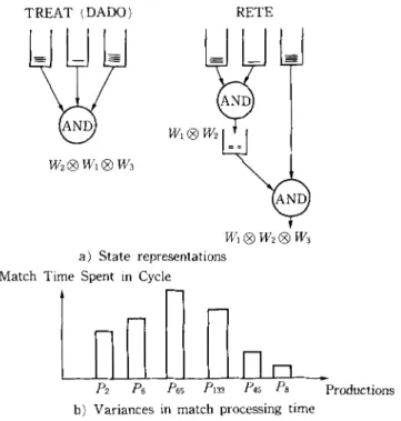
As W M E s are inserted to or deleted f r o m o n e o f the Ri the intermediate i n f o r m a t i o n is updated, a l o n g with the affected c o n d i t i o n element memories. O n the o t h e r hand, the T R E A T algorithm, 8/keeps no intermediate j o i n i n f o r m a t i o n b u t o n l y the Re. It r e c o m p u t e s the j o i n whenever a new w o r k i n g m e m o r y element is inserted to one o f the Rz and n o n e o f the others is empty. This gives T R E A T the flexibility o f d y n a m i c a l l y ordering the intermediate j o i n s so as to m i n i m i z e the a m o u n t o f intermediate c o m p u t a t i o n . F i g u r e 2 shows the state representations in T R E A T a n d R E T E for a p r o d u c t i o n with c = 3 c o n d i t i o n elements.
T h e state m a i n t e n a n c e schemes o f R E T E a n d T R E A T represent a rather conservative a p p r o a c h in t h a t they try to reduce or m i n i m i z e the total a m o u n t
~g It is assumed that all the condition elements are positive.
| denotes the join operation. For example, R~ | R2 contains all pairs of working memory elements the first of which is in R1 and the second in R2 and are mutually compatible with respect to any variable references between the first and second condition elements.
292 K. Ofla~r TREAT (DADO) W2| W1 | W3 RETE ND W~| WI | W2 | W3 a) State representations
Tln
P~a3 P4s Ps Productions Match Time Spent in Cycle/~ Ps P6~
b) Variances in match processing time
Fig. 2 State representations in RETE and TREAT and the resulting variances.
Time Time
P2 Ps P6s PI~3 P4s P8 productions Pz P6 P6s P1~3 Pas P8 Productions
Time l
?
V--'JV-? [""1 F"I V--1 [--'] [ ~ [~l ] ~ [ ~ V---lf-"l [ ~ ~ Productions
& P~ P~ PIa3 P,s P~
Fig. 3 Motivation for the parallel algorithm.
o f c o m p u t a t i o n to update the state. This, of course, is very desirable when the interpreter is implemented on a uniprocessor. However, this need not be the case with parallel c o m p u t a t i o n . Such a conservative a p p r o a c h creates substantial variances in the processing times for the p r o d u c t i o n s affected each cycle, thereby reducing the available p r o d u c t i o n level parallelism as depicted in Fig. 2. Here for example productions ['as and Paaa (processed together in some cycle) take m u c h longer than the other p r o d u c t i o n s affected, effectively reducing p r o d u c t i o n
Highly Parallel Execution of Production Systems: A Model, Algorithms and Architecture 293
level parallelism.
Figure 3 presents the main m o t i v a t i o n behind the algorithm D Y N A M I C - J O I N . The basic idea is to split p r o d u c t i o n state processing into m u c h smaller units (as depicted by the middle graph) and then process these units in parallel if possible (as depicted in the lower graph). The a p p r o a c h presented here distributes m o s t of the c o m p u t a t i o n that is required "suddenly", over to more than one cycle a n d over to m a n y processors. The state representa- tion is substantially different from those used in R E T E or T R E A T . This representation allows the state information to be divided into independently processable units thereby e n a b l i n g the exploitation o f a second level of finer grain parallelism in addition to production level parallelism. A n o t h e r feature o f this representation is that it allows the m a x i m u m a m o u n t o f c o m p u t a t i o n (some o f it potentially redundant) to be done on the state o f a production. So in this respect, in the spectrum of possible state maintenance schemes the algorithm to be presented is almost at one extreme (Match Box 12~ being more extreme) while T R E A T is at the other (conservative) extreme with R E T E and its variations explored by Gupta, 4/ in between.
w
A New Representation for State of a Production
Given a production P, with c condition,* a actions P: C1C2...Cc
AIA2...Aa, let Ri denote the set of W M E s that satisfy the constant tests of (7,.. A
special working m e m o r y element, X - c a l l e d the null W M E - i s assumed to satisfy all the condition elements of a p r o d u c t i o n hence is in each R;. Also associated with each c o n d i t i o n element C~ is a set o f c - 1 intercondition tests
Tis (j = 1 ... c, j =r i). F o r w o r k i n g m e m o r y elements 000)~ ~ Ri and cos ~ Rj, T~fi0)i, cos)=
true,
if the two W M E s are consistent with respect to the intercondition variable tests between condition elements i and j.**At this stage, a simple p r o d u c t i o n will be presented and examples will be developed on the way to clarify some o f the concepts. The example p r o d u c t i o n has three condition elements, and intercondition tests as follows:
(p example
1. T12((.01, 00002): T2](00002, (-/)1):
(typel "fl I "fZ <x>) (0)1. f 2 = 0 ) 2 . b l )
(type2 Abl <x> -b2 <y>) 2.
Tla(0)I, 0)3): T31(0)3, 00001):
(type2 -hi <y> -b2 <> <x>) (wl. f 2 ~ 0)a.b2)
- - ) 3. T23(0)2, 0)3): T3z( 000)3, 0)2):
(make typel "fl (x> "f2 (y>) (w2.bl =/= 0)3.b2) and (00002. b2 = 0)3.bl)
F o r example T2a captures the constraint that the b l field value o f W M E s matching the second condition e l e m e n t - b o u n d to variable <x) -- should be different from the b2 field value of W M E s matching the third condition element
* Some of which may be negative condition elements. ** One can use half the tests since T,j(coi, cos) = T~i(ws, wi).
29d K. Oflazer
a n d t h a t b2 field value o f the W M E m a t c h i n g the s e c o n d c o n d i t i o n e l e m e n t - - b o u n d to variable < y ) - s h o u l d be equal to the bl field value o f the W M E m a t c h i n g the third c o n d i t i o n element.
S u p p o s e that at s o m e p o i n t d u r i n g e x e c u t i o n the w o r k i n g m e m o r y c o n t a i n s the f o l l o w i n g W M E s : * W,: (typel l'fl I t f 2 IZ) W2:(typel l'fl 2 t f 2 14) W3:(type2 l'bl 12 1'b2 14) W4:(type2 l'bl 12 1'b2 12) Ws: (type2 1' b l 14 1' b2 34)
T h e sets R,- c o r r e s p o n d i n g to the c o n d i t i o n e l e m e n t memories w o u l d be: R, = {X, W,}
R2 = R3 = {X, Wa, W4, W5}.
F o r example, Wl has a type field typel and its fl field has value 1 as required by the first c o n d i t i o n o f the e x a m p l e p r o d u c t i o n .
T h e state o f a p r o d u c t i o n P, d e n o t e d by S ( P ) is a subset o f the cartesian p r o d u c t R1 X R2 X ... X Rc a n d consists o f a set o f instance elements. A n instance element is a c-tuple o f slots:
IE = <(h, a~,) ( t~, a)D...( tc, we)>.
T h e ith slot o f the instance element consists o f a tag ti a n d a W M E (z)i where coi ~ Ri. W i t h i n each instance element, any t w o W M E s wi ~ Ri and co~ ~ R~- (either o r b o t h m a y be • are consistent with respect to To with the a s s u m p t i o n t h a t the null W M E • satisfies all i n t e r c o n d i t i o n tests, that is T,u(co;, • = To-(• co j) = Tij(• X) = true. F o r example, the f o l l o w i n g are some o f the instance elements that can be c o n s t r u c t e d for the e x a m p l e p r o d u c t i o n with the state o f the w o r k i n g m e m o r y as given above. IEl: <(tn IEz:
((t21
lEa: <(t3, rE4" <(t41 IE~: <(ts, IE6:<(t61 lET:<(t71
W,) (t,2, W3) (t,3, Ws))
W,) (t22, W4) (t23, W3))
X) (taz, X) (t33, W4))
X) (t,~, W~) (t,~, X)>
W,) (t~, X) (t~, W3>
X) (t6z, W,) (t~3, X)>
W,) (t~, X) (t~, X)>
It c a n be seen that the definition for the instance elements a b o v e allows c o n s t r u c - t i o n o f instance elements t h a t c o n t a i n i n f o r m a t i o n t h a t is r e d u n d a n t with respect to o t h e r instance elements. F o r example, in the set o f instance elements above, IE5 captures the i n f o r m a t i o n that W, in slot 1 agrees with W5 in slot 3. H o w e v e r , * In the following discussions W will be used to denote a specific WME and o~ will be used to
Highly Parallel Execution of Production Systems: A Model, Algorithms and Architecture 295 IEI c o n t a i n s the same i n f o r m a t i o n plus the i n f o r m a t i o n that W3 in slot 2 agrees with b o t h W, and W5. T h u s IEs is redundant. Similarly, the i n f o r m a t i o n in IE~ is c o n t a i n e d in the instance e l e m e n t IE2. In o r d e r to formalize this n o t i o n o f r e d u n d a n c y , the f o l l o w i n g relation between t w o instance elements o f a p r o d u c - t i o n IF a n d IF' is defined. A n instance element IE is covered by IF' ( d e n o t e d as IE IE') if for all i: 1 < i _< c, either wl = w;. or coi = X. This is e q u i v a l e n t to saying t h a t tE' c o n t a i n s the m a t c h i n f o r m a t i o n in IE. This relation is reflexive, a n t i s y m m e t r i c a n d transitive a n d thus induces partial ordering o n the set o f instance elements. T h e instance elements that are n o t r e d u n d a n t are the m a x i m a l elements in this partial o r d e r i n g .
T h e state o f a p r o d u c t i o n is defined to be the set o f the instance elements that are n o t r e d u n d a n t . T h u s in the example avove o n l y IE,, IE2, lea a n d IE4 w o u l d m a k e u p the state. M o r e f o r m a l l y , let
I E S ( P ) = {IE = <(h, wl) ... (tc, We)): Wi ~ Ri A To(wl, cos) = true, 1 _< i < j <- c}
T h e state o f a p r o d u c t i o n , S ( P ) , can then be defined as:
S ( P ) = {IE: IE ~ I E S ( P ) A (VIE' ~ I E S ( P ) A IE' ~ IE A l E glE')}. This w a y o f keeping the state is equivalent to m a i n t a i n i n g a "super" AND-node t h a t j o i n s all c o n d i t i o n element memories d y n a m i c a l l y (hence the n a m e D Y N A M I C - J O I N ) w h e n e v e r a n y j o i n a b l e W M E s are a d d e d to a n y o f them. T h e super AND-node c o n c u r r e n t l y m a i n t a i n s n o n - e m p t y j o i n s R~I | ... N Rij for all {i~ ... 6} c_ {1 .... , c}. A n y such Ri, @ ... N
R#,
1 <_ j < c, c o n t a i n s o n l y those j - t u p l e s o f w o r k i n g m e m o r y elements (co~ ... colj) t h a t are all m u t u a l l y c o m p a t - ible, a n d are not in any o f the sets IIi ... ~'~ ( R k l | ... |Rkt)
where {il ... 6} CR1 R2 R1 | R2 I R2@R3 L @Ra R y R1 R 3~.. f ..t., "!~a md - -RI| R~ ~2 / la)l, X, Xll IX, o~2, XI 'r X, X, ~o3', o~, co2, X'~ X, ~o2, oJ31 ~o,, X, oJ3 ~, O)l, 0)2~ 0)31
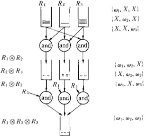
296 K. Oflazer {kl .... , k~} and IIi ... # (...) denotes the relational projection operation m o f the a r g u m e n t relation over c o l u m n s il . . . 4-.* F o r e x a m p l e the pair o f m u t u a l l y c o m p a t i b l e W M E s (W,, W2) need not be kept in R1 | R2, if there is a 3-tuple (W~, W2, W3) in Ra | R2 | Ra, since the information in the former is a v a i l a b l e in the latter. Figure 4 presents a logical view of the state representation in terms of the intermediate state kept for p r o d u c t i o n with 3 c o n d i t i o n elements. A detailed example o f how a state is formed and maintained, will be presented later in this p a p e r to clarify some of the concepts above.
4 . 1 The Tags
A W M E W matching c o n d i t i o n element i o f P (and hence in Ri) m a y be in the ith slot o f one or more instance elements in S ( P ) . When instance elements are m a n i p u l a t e d after insertions and deletions to and from the working memory, some r e d u n d a n t information m a y be generated. It is possible to detect and eliminate s o m e of this r e d u n d a n c y by using additional information in each instance element. The tags associated with the slots in an instance element serve this purpose.
One o f the occurrences o f W in a given slot position is m a r k e d as containing the m a s t e r c o p y o f that working m e m o r y element for that slot position. Other occurrences are tagged as containing either n e w or o l d copies depending on how and when the working m e m o r y element is inserted into that slot. Instance elements that a c c o m m o d a t e W during the cycle it is inserted to the w o r k i n g m e m o r y get to use the tag n e w or m a s t e r . On the other hand, when new instance elements are generated from existing ones, some of the slots from the generating instance element are copied to the newly generated instance element. The slots whose W M E s are copied, are tagged with the tag old. In the u p c o m i n g discussions, the following symbols will be used to denote the tags.
(1) m: Indicates that the a c c o m p a n y i n g W M E is master copy for this slot. There can be only one instance element with an m tag associated with a given working m e m o r y element in a given slot position.
(2) n: Indicates that the a c c o m p a n y i n g W M E is a new copy for this slot. There m a y be m o r e than one instance element that has an n tag for a W M E filling a given slot position.
(3) o: Indicates that the a c c o m p a n y i n g W M E is an old copy for this slot. This instance element was generated from another instance element and this slot's working m e m o r y element was copied from there.
(4) x: Indicates that the a c c o m p a n y i n g W M E is the null element.
Given IE = <(tl, W~) (tz, W~),,.(tc, We)> and M = {sl, sz ... s~} c_ {1, ..., c}, denoting a subset o f the slots in the instance element, the following are interesting c o m b i n a t i o n s o f tags that convey useful information:
* The join relation can be abstracted as a collection tuples where each element of the tuple represents a WME
Highly Paraltel Execution of Production Systems: A Model, Algorithms and Architecture 297 ( l ) m --> 1 and tsl = t~ = . . . . t~m : o: This instance element was generated f r o m a n o t h e r instance element and the W M E s c o r r e s p o n d i n g to the slots in M were c o p i e d f r o m there. Hence, there is some other instance e l e m e n t in the state with the same W M E s in these slots with at least o n e o f the c o r r e s p o n d i n g tags b e i n g n or m.
(2) m : i a n d t~, = n: T h i s indicates that there is some other instance element in the state t h a t has the m tag in the slot s~.
In the state o f a p r o d u c t i o n , all the instance elements have at least o n e slot t h a t has an m o r n tag. Otherwise, if all slots in an instance element h a v e o or x tags, then instance must have been c o p i e d f r o m a n o t h e r one with exactly the same w o r k i n g m e m o r y elements in the slots with the o tags, hence the f o r m e r instance element w o u l d be r e d u n d a n t . Also, if an instance element has o n l y o n e slot full, then this slot s h o u l d have the m tag, a n d there s h o u l d n o t be any o t h e r instance element c o n t a i n i n g the same W M E in the same slot position.
w P r o c e s s i n g a n I n s t a n c e E l e m e n t
5 . 1 M a t c h i n g a N e w W o r k i n g M e m o r y E l e m e n t to an I n s t a n c e E l e m e n t M a t c h i n g a new W M E Wnew satisfying the ith c o n d i t i o n element o f the p r o d u c t i o n , to an instance element IE : ((tt, cot) (t2,
aJ2)...(tc, (.Oe))
involves e v a l u a t i n g the i n t e r c o n d i t i o n tests Ti~(W .. . . cos) for all j such that i 3: j , w~ R~ a n d w~ 4= • Let F be the n u m b e r o f slots in the instance element with a n o n - n u l l w o r k i n g m e m o r y element, and let M d e n o t e the set o f indices o f such slots w i t h w o r k i n g m e m o r y elements agreeing w i t h the new W M E , that isM = {j: i 4= j A w~ ~ Rj A co: 4= X A Ti:(W . . . . w j) = true}.
T h e f o l l o w i n g m a y be the only o u t c o m e s o f the m a t c h i n g Wn~w to an instance element:
(1) I M l =
0: T h e new W M E is not consistent with any o f the n o n - n u l l w o r k i n g m e m o r y elements in the slots o f the instance element, or all slots other t h a n the ith have null W M E s . N o n e w m a t c h i n f o r m a t i o n c a n be derived f r o m instance element.(2) [ M I = F : In this case, the ith slot o f the instance element IE c o n t a i n s X, a n d all the i n t e r c o n d i t i o n tests evaluate to true. T h e u p d a t e to the state consists o f m o d i f y i n g this instance element to
IE : ((th (-01)...(/i-1, (L)i-1) (m/n, Wnew) (/i+1, fOi+l)...(tc, (Oc))
that is, the null W M E in slot i is replaced with the new W M E a l o n g with a n or m tag.
(3) 1 <_ I M I < F : T h i s is the case where a n e w instance element m a y be generated. There are t w o subcases that m a y lead to this case:
298 K. Oflazer (a) All the tested slots o f the instance element agree with Wnew but a)i :/: X. This case is analogous to the case (2) above, except that the ith slot is
not
empty and hence can not a c c o m m o d a t e the matching w o r k i n g memory element.(b) Some o f the W M E s in the tested slots o f the instance element disagree with W .. . .
I f M satisfies any o f the conditions presented at the end o f Section 4.1, then clearly any new instance element that will be generated from this one will be redundant since the same information will be generated from some other instance element. In this case, no new instance element needs to be generated. Otherwise, a new instance element
I E ' =
((t'~, w'~)...(t'~.-t, co'~_,) (t'~, co'~) (t'~+l, co'~+,)...(t'~, w'~))
is generated to be added to the state, where
w~ = w~ and t~ = o for all j ~ M (copy all agreeing slots with tags set to old.)
co;- = X and t;- = x for all j , j 4= i and j ~ M (put null working memory elements to slots corresponding to disagreeing or null slots in the original instance element.)
w;. = W,~w and t;. = n or m (and insert the new W M E to the ith slot.)
5 . 2 Updating an Instance Element after Deleting a Working Memory Element
Processing the effect o f the deletion of a W M E Wde~ on an instance element of a production is much easier since no intercondition variable consis- tency tests have to be performed. Basically, all the slots o f the instance element that contain Wdel are modified so that now contain the null W M E • The modified instance element
m a y
contain information that is now redundant. In this case, the instance element is deleted from the state.w P a r a l l e l Algorithms for Maintaining the S t a t e o f a Production The condition element memories of a p r o d u c t i o n (the sets Ri) change as W M E s matching its condition elements are inserted and deleted. In the state representation above, each instance element in state o f a production has to be processed in response to any change to the condition element memories associat- ed with the production. State processing involves two phases:
(1) processing the instance elements for matches to the W M E inserted or deleted,
(2) checking the instance elements for r e d u n d a n c y and eliminating any redundant instance elements
Highly Parallel Execution of Production Systems: A Model, Algorithms and Architecture 2 9 9 In the first phase individual instance elements can be processed indepen- dently in parallel provided sufficient number o f processors are available. T h u s a second level of parallelism in state processing can be exploited in addition to the p r o d u c t i o n level parallelism exhibited by the p r o d u c t i o n system.
In the second phase, s o m e of the instance elements that are modified a n d /
or generated during first phase are eliminated if they are found to be redundant. It should be noted that any redundancy checks in this phase involves checking those instance elements against others, since their redundancy can not be detected by using tags only. Whenever some instance element is found to be redundant, any critical tag information in that instance element has to be transferred to the instance element that covers it. This guarantees that m a n d n tags in any instance element do not get lost.
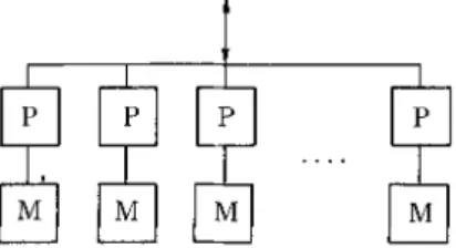
The following discussions will present algorithms for parallel processing of the set o f instance elements of a production. T h e model of parallel c o m p u t a - tion that will assumed for these parallel algorithms (shown in Fig. 5) has the following properties:
[0
Fig. 5 Logical view of the parallel model o f computation.
The state of a p r o d u c t i o n is assigned to be processed by k _> 1 processors. Each processor holds a subset of the instance elements. Ideally there would be only one in each processor.*
Each processor has its own local m e m o r y and processors do not share memory.
The processors receive working m e m o r y changes over a c o m m u n i c a t i o n m e d i u m and also c o m m u n i c a t e with each other (during redundancy checking) using this medium.
6 . 1 P r o c e s s i n g the S t a t e after an Insertion
When a W M E is inserted to the w o r k i n g m e m o r y and matches one or more condition elements o f a production, all the instance elements o f that p r o d u c t i o n have to be processed in order to determine what additional informa- tion should be added to the state. H o w e v e r in order to strictly m a i n t a i n the n o n - r e d u n d a n c y constraint on the state, any r e d u n d a n t instance elements should
300 K. Oflazer
be eliminated after processing the state for each condition element matching the WME. The reasons for enforcing the non-redundancy constraint is to prevent spurious growth in the state and in certain instances prevent the generation o f incorrect information in the state o f productions with negative condition elements.*
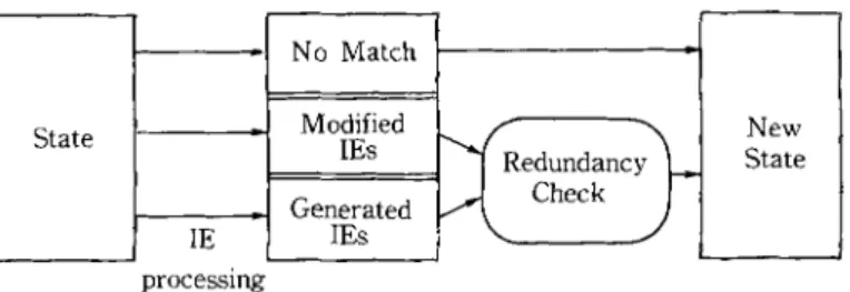
W h e n the state of a production is processed for an insertion after a w o r k i n g memory element matches one o f the condition elements, there will be three sets o f instance elements as shown in Fig. 6.
State -I
I
_I Ig -I processing No Match Modified IEs Generated IEs " ~ Check JFig. 6 Changes in the state after an insertion. New State
(1) instance elements that could accommodate the new W M E and hence were
modified,
(2) instance elements that were generated from other instance elements that could not accommodate the new WME, and
(3) instance elements that did not match the newly inserted working memory element.
If the state did not have any redundant instance elements prior to the insertion, it can be seen that none of the modified instance elements can be r e d u n d a n t after the insertion. The reason for this is that since these instance elements were not redundant before the insertion, modifying one o f their empty slots with the new W M E can not make them redundant. This implies that the redundant instance elements (if any) are among the set o f generated instance elements, and they will be covered by either a modified instance element or by some other generated instance element.
The only issue that seems to require some form o f communication in the instance element processing phase of state processing after an insert involves resolving which instance element in the state gets to use the master tag for the inserted working element in the matching condition element slot and this can be solved by a number o f simple approaches, m
Once the selection is over, all the processors start processing their subset of the instance elements in parallel. When all processors processing the instance
Highly Parallel Execution of Production Systems: A Model, Algorithms and Architecture 3 0 1 elements are finished, the redundancy checking phase starts. In order to elimi- nate any such instance elements, the following sequence of operations take place:
(1)
Starting with processor 0, processors with generated instance elements broadcast these to all the processors assigned to that production. (2) After an instance element is broadcast for redundancy checking, all theprocessors check in parallel to see if any o f their modified or generated instance elements cover the broadcast instance element. I f the instance element is covered, and it has the rn tag, then this tag is copied to the covering instance element. Otherwise, the processor with the smallest n u m b e r of instance elements for that production, adds the broadcast instance element to its subset of the state. This tries to attain a balanced distribution of instance elements across the processors assigned to a production.
(3) W h e n all processors broadcast their potentially redundant instance ele- ments, the redundancy check phase is over, and the processors either complete processing this p r o d u c t i o n or proceed with the next condition element matching the inserted W M E .
6 . 2 Processing the State after a D e l e t i o n
When a W M E is deleted from the w o r k i n g m e m o r y , all the instance elements in the state o f a p r o d u c t i o n have to be processed in order to m o d i f y those that contain the deleted W M E . C o n t r a r y to the case in insertion, the state has to be processed only once even if the W M E h a d matched more than one condition element o f the production. Again, processing the state consists o f two phases: processing the instance elements for the deletion, and performing the r e d u n d a n c y check afterwards to eliminate any r e d u n d a n t information that c o u l d not be detected by the use o f tags.
After the state is processed for a deletion, there will be two sets o f instance elements:
(1) instance elements that were modified (had one or more slots replaced with X) during the delete,
(2) instance elements that were not modified during the delete.
The only instance elements that m a y be potentially r e d u n d a n t after a delete are a m o n g the first set o f instance elements.
As in the insert operation, the instance elements are assumed to be on k processors. Once the selection is over, all the processors start processing their subset o f instance elements m o d i f y any instance elements that contain the delete W M E in their slots.
302 K. Oflazer
w
A Short Example
T h i s section will present a short example to demonstrate the concepts presented a b o v e - a more c o m p l e t e examples can be f o u n d in author's thesis, u) The e x a m p l e will use the p r o d u c t i o n presented earlier in Section 4.
Cycle 1: I N S E R T W l :
(typel ?fl I ?f2 IZ)The w o r k i n g m e m o r y element matches the first condition element. Initially there are no instance elements in the state, so processor 0 generates a singleton instance element with only the first slot filled.
Proc # State Generated IES
o
--<(m, w,)(x, x)(x, x)>
The generated instance element is then added to the state. Proc # State
o <(.i, w,)(x, x) (x, x)>
Cycle
2: I N S E R T Wa : (type2 "r b l 12 1' b2 14)This W M E matches b o t h the second and the third c o n d i t i o n elements. First the state is processed for the second condition element. In instance element IE~, W3 agrees with Wl in slot 1. Hence W3 fills up the empty second slot in this instance element modifying it to:
Proc # State
0 IEI: ~(m, Wl) (m, W3) (x, X))
Since there are no generated instance elements, there is no need for a redundancy check. N o w the resulting state is processed for the m a t c h to the third condition element. In IE~, W~ in slot 1 agrees with W~ in slot 3, however W3 in slot 2 disagrees with W3 in slot 3 since the variable <y) can not be b o u n d to the same value in both WMEs. In this case, a new instance element is generated with the informa- tion in the matching slot copied.
Proc # State Generated IES
0 IE,: <(m, W,) (m, Wa) (x, X)> <(o, Wl) (x, X) (m, Wa)>
After redundancy check, the generated instance element is added to the state on processor 1. The state o f the production is n o w
Porc # State
0 IE~: <(m, W,) (m, Wa) (x, X)> I IE2: <(o, W,) (x, X) (m, Wa)>
w
A Parallel Processor Architecture
T h e following sections present the architecture for a parallel processor for p r o d u c t i o n systems that can be used to implement the parallel algorithm
Highly Parallel Execution of Production Systems: A Model, Algorithms and Architecture 3 0 3 presented in the preceding sections followed by a high-level description o f its operation. Subsequently, results from simulation experiments with the p r o p o s e d algorithm and architecture will be provided.
w
Structure of the P a r a l l e l Processor
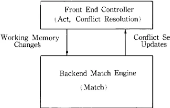
T h e parallel processor is envisioned as back-end match engine (as depicted in Fig. 7) that implements the match part o f the production system interpretation cycle. This engine is connected to a front-end system that is responsible for interfacing to the users, executing the act and conflict resolution functions in addition to controlling the parallel processor. T h e interface between the match engine and the front-end controller is a simple one: for every action that modifies the w o r k i n g memory, a c o m m a n d (insert or delete) is sent to the match engine along with the W M E involved. T h e match engine responds by sending any changes to the contents of the conflict set. It is expected that the front end system will be a conventional processor that is fast enough to match the performance o f the back end.
Front End Controller (Act, Conflict Resolution) Working emory
Changeg Confl Updates Set
Backend Match Engine (Match)
Fig. 7 Partitioning of PS Interpreter functions.
The parallel algorithm presented earlier exploits two levels o f parallel- ism: processing the state o f the productions affected by a working m e m o r y chage, in parallel, and processing the instance elements in the state o f each p r o d u c t i o n in parallel. This necessitates a structure with a large n u m b e r o f processors-- possibly in the range of 256 to 1024. However, contrary to other p r o p o s e d highly-parallel architectures for production systems (e.g., D A D O , TM N O N - VON7~), instead o f allocating dedicated processors to each production, the processors are to be multiplexed to the large n u m b e r productions in the produc- tion system, since during each cycle the states o f only a small n u m b e r o f p r o d u c t i o n s need to be processed. The processors have their own memories, do not share any m e m o r y and operate in M I M D m o d e (see Ref. 11) for a detailed discussion on the requirements o f the architecture). These considerations above necessitate a structure where groups of processors can be organized into groups of possibly different sizes and that the organization o f these clusters can change
304 K. Oflazer from cycle to cycle depending on the productions that are being processed during the cycle. T h e c o m m u n i c a t i o n network provides dedicated paths a m o n g the processors organized into a group.
Controller ]
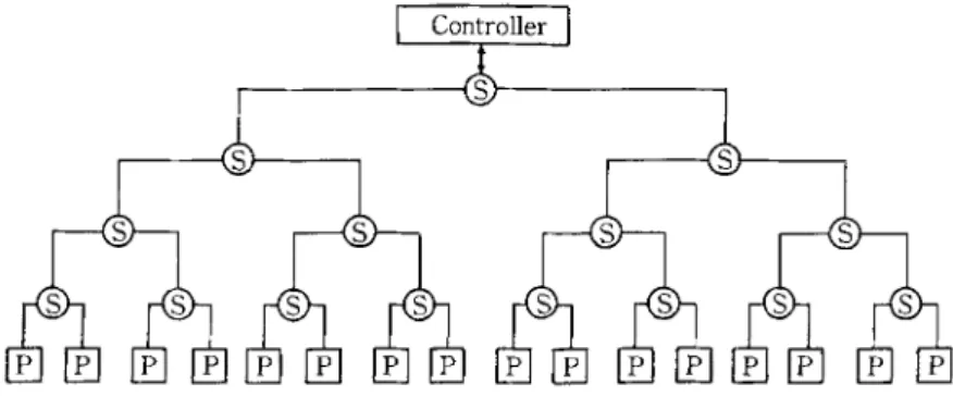
P : Instsnce Element Processors S : Switches
Fig. 8 Structure of the proposed parallel processing system.
A very suitable structure that fits the requirements duscussed above is an array o f K = 2 M processors at the leaves of a binary tree consisting of K -- 1 switches as depicted in Fig. 8. The switches constitute the c o m m u n i c a t i o n network that connects the processors to the front-end controller and to each other. This parallel processor structure is m o d u l a r and extensible and can be i m p l e m e n t e d employing switches and processors built with the VLSI technol- ogy. G r o u p s o f processors ( o f certain selected sizes) can be created on this structure by allowing certain switches logically disconnect subtree underneath them f r o m the rest o f the tree. Each o f these groups then have their o w n independent c o m m u n i c a t i o n networks during r e d u n d a n c y checking. Further- more the configuration and the n u m b e r of the groups can be changed from cycle to cycle, though within the limits o f the tree organization. The binary tree o f the switches also provides a very suitable organization for providing certain func- tions during redundancy checking.
This parallel processor organization is substantially different from those of D A D O TM and N O N - V O N , 7~ since processors are only at the leaves, and the internal nodes of the tree are used to implement a c o m m u n i c a t i o n and reconfiguration network. Furthermore, in contrast to N O N - V O N in which processing elements are very simple pattern matching machines that operate with instructions received from a control unit, the processors in this organization have the complexity o f a microprocessor and operate in M I M D mode.
T h e two levels o f parallelism mentioned earlier can be m a p p e d o n t o this structure as follows: P r o d u c t i o n s are assigned to be processed by a processors that comprise the leaves o f a complete subtree o f switches. A production P is assigned to be processed by k = 2 '~ processors that correspond to the leaves o f
Highly Parallel Execution of Production Systems: A Model, Algorithms and Architecture 3 0 5
Table 1 Hypothetical processor requirements of productions for an example production system. Productions : Pl P2 P3 P4 P5 P6 P7 P8 P9 PI0 Pll P12 Processors : 2 2 4 8 4 4 2 1 1 4 8 8 ] Controller ] 0 1 2 3 4 5 6 7 8 9 10 11 12 13 14 15 [ - ' - f f ~ I P3 ] I P4 I
I
P5
] [
P6
I ~
[ ] [ ] ]
PIO
[
]
Pll
] I
P12
[
Fig. 9 A possible assignment of productions for the example production system.
[ Controller I
0 1 2 3 4 5 6 7 8 9 10 11 12 13 14 15 l--Vi -] [ - - a - - ] I P3 ] I - - - ~ I PIO ]
. indicates that the subtree is logically isolated from rest of the tree.
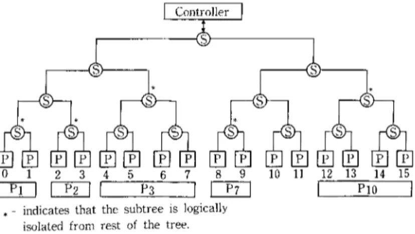
Fig. 10 Switch configuration for processing Pl, P2, P3, P7 and Pf0.
a p r o p e r s u b t r e e o f t h e l a r g e tree. T h u s , P c a n o n l y b e a s s i g n e d to t h e leaves o f o n e o f t h e 2 M m subtrees, w i t h t h e l e f t m o s t p r o c e s s o r l a b e l e d 0, 2 m, 2 ~ m .. . . . (2 M-m - - 1). 2 m. T h e f o l l o w i n g e x a m p l e s w i l l c l a r i f y h o w t h e s w i t c h e s o p e r a t e t o i m p l e m e n t r e c o n f i g u r a t i o n o f t h e p r o c e s s o r s . S u p p o s e a n e x a m p l e p r o d u c t i o n system h a s 12 p r o d u c t i o n s , t h e p a r a l l e l p r o c e s s o r h a s K = 16 p r o c e s s o r s , a n d t h e p r o d u c t i o n s h a v e p r o c e s s o r r e q u i r e - m e n t s as s h o w n i n T a b l e 1. F i g u r e 9 p r e s e n t s o n e w a y o f a s s i g n i n g t h e s e p r o d u c t i o n s to t h e p r o c e s s o r s . F o r e x a m p l e , if d u r i n g a cycle, p r o d u c t i o n s P I, P2, P3, P7 a n d PI0 are to b e p r o c e s s e d t o g e t h e r , t h e n it w i l l b e p o s s i b l e to d o t h i s
306 K. Oflazer without any processor having to process more than one production. In this case, the processors would be configured into an organization where five groups o f processors would operate independently as depicted in Fig. 10. The switches at the roots o f the subtrees to which these productions are assigned would (logi- cally) disconnect the subtrees from the rest of the tree so that the redundancy check phases of these productions can proceed concurrently using the indepen- dent c o m m u n i c a t i o n paths established via the reconfiguration. If on the other hand P I, P2, P4, P5, PT, P l 2 have to be processed as a result of an action during a cycle, then processors 0 t h r o u g h 3 and 10 through 15 would sequentially process the state of two productions, while processors 8 and 9 would process the states o f three productions.
w
Operation of the Parallel Processor
At a very high level, the interface o f the parallel processor to the front end controller is a simple one. The controller sends c o m m a n d s of the form
INSERT(W) DELETE(W)
to insert or delete WMEs from the working memory, and the processors respond by sending messages to insert or delete production instantiations from the conflict set maintained by the front-end controller.
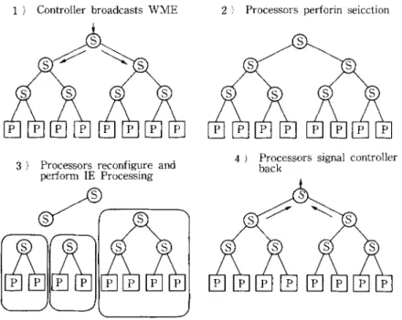
When the controller issues an insert c o m m a n d - - I N S E R T ( W ) - t h e field values for the W M E are broadcast to all the processors via the tree o f switches.
1 ) Controller broadcasts WME
a) Processors reconfigure and perform IE Processing
2 ) Processors perforin seicction
4 ) Processors signal controller back
Highly Parallel Execution of Production Systems: A Model, Algorithms and Architecture 3 0 7 Each processor at the leaves o f the tree perform the selection phase o f the match cycle for the subset o f the productions assigned to it. This selection phase within each processor can be implemented by very small versions of the discrimination network used in the uniprocessor R E T E interpreter) > The selection process within each processor identifies a set o f productions (along with their matching condition elements) whose states have to be processed by that processor.
After the selection, the instance elements o f those productions selected are processed as described earlier (see Ref. l l) for the details of the procedures). When a processor completes processing the states o f the productions assigned to it, it sends a DONE signal to its parent switch. When a switch receives the DONE signal from both of its sons (processors or switches), it passes the signal to its parent switch. Finally when the topmost switch receives the signal from its sons, it passes the signal to the controller indicating that the match cycle has been completed. The operation for a delete operation is exactly the same. Figure 11 outlines the phases of a typical match cycle, R e d u n d a n c y check stage follows the instance element processing during which the processors are reconfigured to form groups o f differents sizes and each groups proceeds with its own redun- dancy check.
w Simulation o f the P a r a l l e l Algorithm and Architecture
This section describes the results from a limited set of simulated execu- tions o f a number o f p r o d u c t i o n systems with the pal"ailel algorithm presented earlier in order to observe its behavior and to get a feeling of potential perfor- mance. These simulated executions have been implemented with a simulator that has been built on top of the Lisp-based R E T E interpreter running on a V A X 11/780 (see Ref. 11) for a detailed discussion on various architectural and timing assumptions made).
The simulator was used with four production systems: XSEL, R1, M U D and EP-SOAR with 1303, 2153, 872 and 62 productions respectively. Traces from two application runs o f X S E L and one run o f the others were available. The first three systems are relatively large real application systems while EP- SOAR is a very prototype small system. However EP-SOAR has a number o f characteristics that make it interesting for D Y N A M I C - J O I N . On the average each production o f EP-SOAR has 10 condition elements--2 to 3 times the number o f condition elements o f the other ones. With the exception of 8 productions (with 58, 47, 27, 20, 20, 16, 13, and 10 condition elements) the produc- tions in EP-SOAR behave reasonably_ There are however a number o f reasons why systems like EP-SOAR are not very suited for this parallel algorithm.
11. I Results from Simulations
(1~ Distribution of average number of instance elements of productions
3 0 8 K. Oflazer
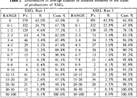
Table 2 Distribution of average number of instance elements in the states
of productions of XSEL, RANGE 0 0-1 1-2 2-3 3-4 4-5 5-6 6-7 7-8 8-9 9-10 I0-15 15-20 20-30 30-50 50-100
XSEL Run 1 XSEL Run 2
P's % Cure, % RANGE P's % Cure. % 579 43.0% 43.0% 0 591 43.9% 43.9% 332 24.7% 67.7% 0-1 322 23.9% 67.8% 129 9.6% 77.3% 1 2 138 10.3% 78.1% 63 4.7% 82.0% 2-3 73 5.4% 83.5% 46 3.4% 85,4% 3-4 34 2.5% 86,0% 29 2.2% 87.6% 4-5 27 2.0% 88.0% 28 2.2% 89.8% 5 6 30 2,2% 90.2% 15 1.1% 90.9% 6-7 13 I 1.0% 91.2% 3 0.2% 91,1% 7-8 21 I 1.6% 92.8% i 6 0.4% 91.5% 8-9 2 0.1% 92.9% 4 0.3% 91.8% 9-10 5 0.3% 93.2% 41 3.1% 94.9% 10-15 28 2,3% 95.5% 35 2.6% 97.5% 15-20 34 2.5% 98.0% 21 1.6% 99.1% 20-30 20 1.5% 99.5% 12 0.8% 99.9% 30-50 7 0.5% 100.0% 2 0.1% I00,0% 50-100 0 0.0% 100.0% a v e r a g e n u m b e r o f i n s t a n c e e l e m e n t s t h a t h a v e t o b e p r o c e s s e d d u r i n g e v e r y c y c l e t h a t t h e p r o d u c t i o n is a f f e c t e d . T a b l e s 2 a n d 3 p r e s e n t t h e d i s t r i b u t i o n o f t h e a v e r a g e n u m b e r o f i n s t a n c e e t e m e n t s f o r t h e p r o d u c t i o n s o f t h e s y s t e m s c o n s i d - e r e d . * F r o m t h e s e r e s u l t s it c a n b e s e e n t h a t f o r t h e t w o l a r g e s y s t e m s X S E L a n d R I, m o r e t h a n 90% o f t h e p r o d u c t i o n s h a v e less t h a n 10 i n s t a n c e e l e m e n t s o n t h e a v e r a g e d u r i n g e x e c u t i o n . F o r M U D a r o u n d 80% o f t h e p r o d u c t i o n s h a v e o n t h e a v e r a g e less t h a n 10 i n s t a n c e e l e m e n t s d u r i n g e x e c u t i o n s . F o r E P - S O A R t h e c u m u l a t i v e p e r c e n t a g e f o r t h e 0 - 1 0 r a n g e is s m a l l e r s i n c e t h e n u m b e r o f p r o d u c - t i o n s is v e r y s m a l l c o m p a r e d t o t h e o t h e r s y s t e m s . * *
* P r o d u c t i o n s that have been split up have been counted as distinct productions, m In XSEL 42
productions (3.2% of the productions) needed to be split up while in Rl only 22 productions ( 1,0% of the productions) needed to be split up, In MUD, 40 productions that were sensitive to every change to the working memory were removed from the system. These were productions for tracing and debugging and their inclusion in the system would distort the statistics and increase simulation time unnecessarily. An additional 43 productions in MUD (4.9% of the productions) were split up. In EP-SOAR, 8 productions with very large number of condition elements (with 58, 47, 27, 20, 20, 16, 13, and 10 condition elements) were removed from the system, since they could not be handled even after splitting. A total of 16 productions (25% of the productions) with relatively large number condition elements (8 to 19) were split up.
* * The average number of WMEs in the working memory during each cycle of the XSEL runs were 177 and 181, while the corresponding figures for the RI run were 243. The MUD run had on the average 235 WMEs, and EP-SOAR had on the average 180 WMEs. These numbers indicate that the working memory size during these runs is relatively small which may be one of the reasons for the distributions above, Selective productions will be satisfied with a very small subset of these working memory elements and thus their state will have a small number of instance elements.
Highly Parallel Execution of Production Systems: A Model, Algorithms and Architecture Table 3 Distribution o f average number o f instance elements in the states
of productions of R1, M U D and E P - S O A R .
Rl M U D EP SOAR
RANGE P's % C u m . % RANGE P's % Cum. % RANGE P's % 0 1650 75.8 75.8 0 541 62.0 62.0 0 6 7.0 0-1 139 6.4 82.2 0-1 56 6.4 68.4 0-1 1 1.2 1 2 175 8.0 90.2 1-2 37 4,2 72.6 1-2 1 1.2 2-3 19 0 . 9 91,1 2 3 t2 1.4 74.0 2-3 7 8.1 3 4 49 2.3 93.4 3-4 8 0 . 9 74.9 3-4 6 7.0 4-5 12 0.6 94.0 4 5 14 1.6 76.5 4-5 5 5.8 5-6 10 0.5 94.5 5-6 2 0.2 76.7 5-6 2 2.3 6-7 15 0.7 95.2 6 7 15 1.7 78.4 6-7 5 5.8 7-8 6 0.3 95.5 7-8 7 0.8 79.2 7-8 4 4.7 8 9 1 0.04 95.5 8-9 10 1.1 80.3 8-9 4 4.7 9-10 1 0.04 95.6 9-10 5 0.6 80.9 9-10 2 2.4 10 15 18 I 0.8 96.4 10-15 15 1.7 82.6 10-15 13 14.6 15-20 27 1.2 97,6 15-20 6 0.7 83.3 15-20 5 5.8 20 30 18 0.8 98.4 20 30 42 4.8 88.1 20-30 5 5.8 30-50 25 1.1 99.5 30-50 97 11.0 99.1 30-50 7 8.2 50 100 10 0.5 100.0 50 100 4 0.5 99.6 50-100 11 12.9 100-200 3 0.4 100.0 100-200 2 2.5 309 Cure. % 7.0 8.2 9.4 17.5 24.5 30.3 32.6 38.4 43.1 47.8 50.2 64.8 70.6 76.4 84.6 97.5 100.0 Table 4 Statistics on the behavior
N u m b e r of W M Actions Avg. Prods. Processed/Cycle Avg, IEs Processed/Cycle Avg. IEs Generated/Insert Avg. IEs Modified/Insert Avg. IEs Modified/Delete
Avg. Redundant IEs eliminated with tags/Delete
Avg. IEs Broadcast for Redundancy Checking/Insert
Avg. Redundant IEs eliminated with R e d u n d a n c y Checking/Insert
of the algorithm for four production XSEL R u n l 1868 23.9 255.7 24.6 20.0 47.2 21.4 22.8 4.8 systems. XSEL R1 M U D E P - S O A R Run2 R u n R u n R u n 1945 1665 2074 924 23.9 14.6 24.4 9 . 5 267.0 206.5 316.2 222.3 25.6 25.6 37.5 122.1 20.3 15.1 29.6 22.7 44.8 39.0 53.6 71.7 22.6 17.7 33.0 24.4 24.1 25.7 23.0 122.0 4 . 6 10.2 4 . 2 [04.9
(21 Run time statistics for the parallel algorithm
T h e s e t o f f i g u r e s p r e s e n t e d i n T a b l e 4 p r o v i d e i n f o r m a t i o n a b o u t t h e a g g r e g a t e b e h a v i o r o f t h e p r o d u c t i o n s y s t e m a s i t i s b e i n g i n t e r p r e t e d w i t h t h e D Y N A M I C - J O I N . * T h e r a t i o o f i n s t a n c e e l e m e n t s p r o c e s s e d p e r c y c l e t o p r o c e s s o r s u s e d p e r c y c l e i s a n a p p r o x i m a t e m e a s u r e o f t h i s u t i l i z a t i o n . F o r t h e s y s t e m s c o n s i d e r e d , it i s 0 . 8 2 a n d 0 . 8 4 f o r X S E L r u n s , 0 . 7 3 f o r R 1 t o 0 . 9 3 f o r E P - S O A R r u n s ; t h a t is o n t h e a v e r a g e a s m a l l n u m b e r o f p r o c e s s o r s a r e e s s e n - It should be noted that some of these nunbers are averages over productions and cycles. For instance, only one production may be responsible for half of the new instance elements generated during a cycle. It is very hard to present such information without v o l u m i n o u s per production statistics.
3 t 0 K. Oflazer tially idle.
(33 Timing results
The time for a match cycle is the sum o f the selection time and the state processing time. Since our algorithm is only concerned with the state processing part o f the match cycle, the timing figures presented in T a b l e 5 correspond to the average time the state processing phase o f the match cycle takes on a simulated parallel execution of these systems with certain assumptions, n) To these numbers one w o u l d have to add the time for selection that takes place within each processor. These numbers are estimated to be around 42 microseconds for selection for XSEL and R1, 80 microseconds for M U D and 38 microseconds for E P - S O A R (see Ref. 11) for details of how this time is determined). Assuming these selection times, a match cycle would complete in about 140 microseconds for X S E L , in 205 microseconds for R1, in 153 microseconds for MUD, and 440 microseconds for EP-SOAR. These translate to ~ 7 0 0 0 wme-actions/sec for XSEL, 4900 wme-actions/sec for R1, 6500 wme-actions/sec for MUD, and 2200 wme-actions/sec for EP-SOAR. They can be favorably compared with the 5 to 10 milliseconds--100 to 200 w m e - a c t i o n s / s e c - f o r the VAX 11/780 BLISS- based interpreter. They represent an order o f magnitude improvement over a VAX 11/780 even if we assume that the uniprocessor interpreter is highly optimized and can perform 500 to 1000 wme-actions/sec. Similarly they com- pare favorably to about 550 microseconds/wine-action reported for NON-VON 7) with 16K simple processing elements and to the estimated 5 milliseconds/ wine-action for 1023 processor D A D O 2 using T R E A T . 14'8) In terms of overall complexity, the architecture proposed here is simpler than both D A D O and N O N - V O N in the sense that only the leaves have processors, and for the p r o d u c t i o n systems considered in this paper, D Y N A M I C - J O I N requires less number o f processors than both the 16K processor N O N - V O N and 1023 proces- sor D A D O and achieves a better (simulated) performance than both. On the other hand, on shared memory multiprocessors Gupta's parallel R E T E algor- ithm achieves very good p e r f o r m a n c e (11,250 w m e - c h a n g e s / s e c with 64- processors 4~ but ~his Mgorithm relies o~ an associative hardware scheduler and performance is considerably lower with distributed software schedulers. In terms
Table 5 Average state processing time from simulated executions.
XSEL Runl Avg. Number of Processors used/Cycle 308
Std. Deviation 395
Avg. State Processing Time/Cycle (ktsecs) 97
Ste. Deviation 125
Avg. IE Processing Time/Cycle (.usecs) 62
Std. Deviation 56
Avg. Red. Check Time/Cycle (/zsecs) 35
Std. Deviation t 90
XSEL RI M U D E P - S O A R
Run2 Run Run Run
315 284 390 239 401 348 426 346 101 163 73 402 130 292 1/5 710 64 55 4l 93 58 51 43 126 37 108 32 309 94 274 75 425