Electrospun Nanofibers Prepared with CdTe QDs, CdTeSe QDs and
CdTe/CdS Core-Shell QDs
Canan Başlak1*, Özcan Köysüren2, Mahmut Kuş3
1Selcuk University, Science Faculty, Chemistry Department, Campus, Konya, Turkey, [email protected]
2Ankara University, Engineering Faculty, Energy Engineering, Ankara, Turkey 3Selcuk University, Engineering Faculty, Chemistry Engineering, Campus, Konya, Turkey
*Corresponding Author Received: 2 January 2018 Accepted: 12 March 2018 DOI: 10.18466/cbayarfbe.373679
Abstract
In this study, a novel method is used to prepare water-soluble CdTe, CdTeSe quantum dots (QDS) and CdTe/CdS core-shell QDs by using Te, Se, NaBH4, and CdCl2 as precursors. Electrospinning method is used to obtain polyvinyl alcohol (PVA)/QDs composite nanofibers. A series of PVA/QDs nanofiber mats with three different QDs content are prepared. Transmission electron microscopy (TEM) and X-ray powder diffraction (XRD) have been used to characterize QD nanoparticles. In addition, for characterization of the composite nanofibers, scanning electron microscopy (SEM) and atomic force microscopy (AFM) have been used. QDs have a good dispersed crystalline structure with an average crystalline size between 2-4 nm. Morphology analyses reveal that the composite nanofibers with an average diameter ranging from 50 to 250 nm are prepared using the electrospinning technique.
Keywords: CdTe Quantum Dots; Polyvinyl Alcohol; Nanofibers; Electrospinning
1. Introduction
There has been great interest in the preparation of quantum dots (QDs) because of their novel optoelectronic properties, which are tunable emission wavelength, high quantum yields (QYs) exceptional photostability and broad absorption cross section [1-3]. The exciton binding energy in QD structures increases remarkably. So, new excitonic optical characteristics can be expected for the wide bandgap materials [1, 2]. There are many companies that produce these fine particles (QDs) designed for some specific applications [4]. Synthetic fibers are produced mostly from polymer-based materials and especially, spinning process is used to prepare synthetic fibers. During the spinning process, polymer-based material is melted and extruded through the fine holes of the die. The spun fibers are stretched and drawn to enhance the polymeric chain orientation and the crystallinity after the extrusion process [5]. Synthetic fibers have specific properties (tensile properties and conductivity) which allow them to be used in different applications. When compared with material’s bulk properties, synthetic fibers spun from polymer-based materials exhibit enhanced properties such as tensile properties, optical and electrical properties. In synthetic fiber preparation techniques, the current trend used is to prepare submicron scale nanofibers, which can be
achieved using the simple electrospinning method. Nanofibers obtained using the electrospinning technique provides a number of enhanced properties such as an increase in surface area/volume ratio, a drop in structural defects and a decrease in pore size. Electrospinning is a fundamental technique to prepare nanofibers. The electrospinning instrument is composed of a syringe, a pump system, two electrodes and a high voltage supply. The solution of the polymer is filled into the syringe and fed from the syringe to the tip of electrode as polymer drop with the help of the pump system. The polymer drop is drawn into fibers on the other electrode, known as the collector, with the help of the high voltage supply. The polymer drop at the tip of the electrode is electrically charged and turn into the polymer jet, which is collected as nanofibers on the collector [6]. Membranes, protective clothings and sensors can be shown as potential applications for nanofibers prepared using the electrospinning process [7]. In addition, electrospun nanofibers have been utilized by many studies as platform for quantum dot based applications, with mentioned advantages such as functional immobilization with desired spacing, high surface area, reproducibility [8-10]. Quantum dots were added into the electrospun nanofiber to label the fibrous structure due to their unique optical properties [8-11].
In this study, polyvinyl alcohol/quantum dots composite nanofibers, including CdTe, CdTeSe QDs and CdTe/CdS core-shell QDs, respectively, are prepared by the electrospinning process. Electrospun nanofibers with high surface area and with unique optoelectronic properties turn the polymeric material into a label. 2. Materials and Methods
2.1. Chemicals for QDs and PVA/ODs nanofibers Chemicals used for QDs preparation, cadmium chloride (CdCl2.5/2H2O), 3-mercapto propionicacid (MPA), selenium powder (Se), tellurium powder (Te), sodiumborohydride (NaBH4) and thiourea ((NH2)2S), were purchased from Sigma-Aldrich. KOH, purchased from Sigma-Aldrich, was used to adjust the pH of the reaction mixture. For this purpose, stock solution of 0.1 mol/L KOH was prepared.
Polyvinyl alcohol, from Inovenso Ltd., Turkey, was used as polymer matrix material. The degree of hydrolysis of PVA ranges from 86 to 89 mol % and the degree of polymerization ranges from 1700 to 1800. The molecular weight of PVA changes from 84000 to 89000 g/mol. 2.2. Synthesis of CdTe and CdTeSe QDs
In the synthesis, MPA-capped Cd based Qdots were prepared by using CdCl2. 5/2H2O, MPA, thiourea, Se and Te powders. Typically, CdCl2. 5/2H2O (n moles) with MPA (2n moles) were used for synthesis and the pH was adjusted to basic conditions with NaOH. The solution was heated to 100 °C under nitrogen for 0.5 h. At 80 oC of temperature, fresh NaHTe aqueous solution was used as precursor solution and was prepared from Te and NaBH4. In order to prepare the selenium precursor solution, Se powder was mixed with 2 ml of fresh NaBH4 in water under nitrogen atmosphere. The precursor solution of Te were injected into the reaction system to obtain CdTe QDs (core QDs). Regular intervals were taken out for characterizations. To prepare CdTeSe QDs (alloyed QDs), Te and Se precursor solutions were simultaneously injected into the reaction media. CdTe/CdS QDs (core-shell QDs) were made in the same way as the reported synthesis procedure of CdTe and CdTeSe QDs. In order to prepare S precursor solution, Thiourea was added in a appropriate molar ratio for used Te amount. The all QDs obtained were precipitated and washed with 2-propanol more than three times.
PVA was dissolved in distilled water at 80 °C with magnetic stirring to obtain 5 wt. % solutions. The composite solution was prepared by mixing the quantum dots, CdTe QDs, CdTeSe QDs and CdTe/CdS (core-shell) QDs, respectively, within the prepared PVA solution. The QDs composition of the prepared composite solutions was kept at 10 wt. %. Electrospinning instrument from Inovenso Ltd., Turkey (NE-100) was used to prepare the composite nanofibers. The composite solution was pulled into a syringe, placed on the top of the pump, and the feed rate of the composite
solution was maintained at 0.1 ml/hr. Due to the high voltage supply, there is an electric potential difference of 30 kV between the electrodes, which are the collector and the syringe tip. The distance of electrodes was provided to be 10 cm. Electrospun PVA/QDs nanofibers were collected on aluminum foil.
2.3. Characterization of QDs and PVA/ODs nanofibers
The surface microstructure of PVA/QDs nanofibers mats was analyzed using EVO LS10 ZEISS model scanning electron microscope (SEM) and Tecnai G2 F30 model atomic force microscope (AFM). The surface morphology of QDs was examined by using JEOL JEM 2100F HRTEM model transmission electron microscopy (TEM). The average diameter of PVA/QDs nanofibers was determined from the SEM images of the composite nanofibers with the help of a software (The National Institutes of Health ImageJ). For this purpose, image analysis was performed on SEM figures and at least 25 different fiber structures were analyzed for each composite system (PVA/CdTe, PVA/CdTeSe and PVA/CdTe/CdS). Image analysis results were given with standard deviations.
XRD patterns of the following quantum dots, which are CdTe QDs, CdTeSe QDs and CdTe/CdS QDs (core-shell), were analyzed with Bruker Advance D8 model X-ray diffractometer with Cu Kα radiation at the wavelength of 0.15406 nm. X-ray diffraction patters were obtained at 1°/min scan speed between 10° and 80°. Average crystalline size of prepared QDs could be determined with the help of the Scherrer equation, given below:
Lc = K λ / (B cos θ) (1) where Lc is the average crystalline size, K is a constant (0.89), λ is the radiation wavelength (0.15406 nm), B is widening of diffraction angle in the middle of Bragg’s maximum and θ is diffraction angle at Bragg’s maximum [12, 13].
A digital color camera was used to record the colors of CdTe QDs aqueous solutions under sunlight. The fluorescent images were recorded under UV light (365 nm) with the digital color camera.
3. Results And Discussions
The XRD diffraction patterns of the prepared CdTe QDs, CdTeSe QDs and CdTe/CdS QDs (core-shell) are illustrated in Figures 1a-c. All the samples showed three characteristic peaks at 2θ = 26°, 43° and 50°, which can be assigned to the diffractions from (1 1 1), (2 2 0), and (3 1 1) planes of the cubic zinc blend crystal structure of CdTe QDs [13, 14]. CdS has three characteristic peaks at 2θ = 27°, 44° and 52°, referred to (111), (220), and (311) planes. The diffraction peaks of CdTe and CdS structures might overlap. When compared with Figures 1a and 1b,
Figure 1c shows broad diffraction peaks because of CdS content of core/shell QDs. The main XRD peaks (1 1 1) was used to estimate the average crystalline size of the as-prepared nanoparticles using the Scherrer equation [13].
a
b
c
Figure 1a, b, c. XRD diffraction patterns of the prepared CdTe QDs, CdTeSe QDs and CdTe/CdS core-shell QDs, respectively.
The average crystalline sizes of CdTe QDs, CdTeSe QDs and CdTe/CdS QDs (core-shell) were calculated to be 2.7 nm, 3.2 nm and 4.0 nm, respectively. With the growth of the CdS shell, the diffraction peak positions of core-shell QDs almost remain constant when compared with the CdTe QDs. In addition, the widths of the diffraction peaks remain almost unchanged and no separate CdS peak is observed, which confirms the formation of a core/shell QD rather than structure of an alloyed QDs [15].
a
b
c
Figure 2a, b, c. SEM images of PVA/CdTe, PVA/CdTeSe and PVA/CdTe/CdS composite nanofiber, respectively.
In Figures 2a-c, the SEM images of PVA/CdTe, PVA/CdTeSe and PVA/CdTe/CdS composite nanofiber systems are given. SEM images prove the presence of nanofiber structures within the composites. The fiber size did not change much with the QDs type. In addition, the QDs content was low and did not alter the fiber structure. PVD/ODs nanofibers have an average diameter ranging from 50 to 250 nm and the average fiber diameter of PVA/CdTe, PVA/CdTeSe and PVA/CdTe/CdS composite nanofiber systems are 116 ± 12 nm, 161 ± 16 nm and 137 ± 13 nm, respectively. The polymer solution properties such as solution viscosity and concentration
are important parameters in the electrospinning technique in terms of the prepared fiber morphology [6, 16]. During the electrospinning process, if the concentration and the viscosity of the polymer solution are relatively low, bead structures can be observed along the fiber structures, which may be the reason for the beaded fiber structures seen on the SEM images of PVA/QDs composite systems (Fig. 2a-c) [6, 16].
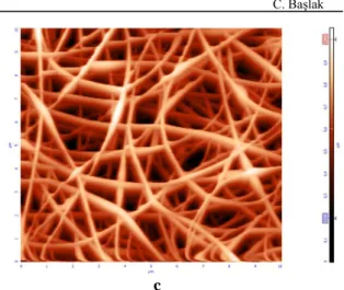
Topographic imaging by AFM of PVA/CdTe, PVA/CdTeSe and PVA/CdTe/CdS composite nanofiber systems reveal fibrous and porous surface features, respectively (Fig. 3a-c), AFM images are consistent with the SEM images in terms of the fiber size. Similar to the SEM images, nanofibers with the diameter at around 100 nm can be observed on AFM images. In addition, AFM images prove the beaded fiber structures, which might result from the low polymer solution concentration.
a
b
c
Figure 3a, b, c. AFM images of PVA/CdTe, PVA/CdTeSe and PVA/CdTe/CdS composite nanofiber, respectively.
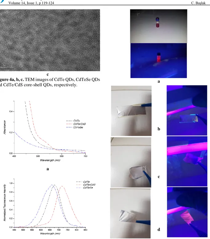
Figures 4a-c show TEM micrographs of CdTe QDs, CdTeSe QDs and CdTe/CdS QDs (core-shell). The presence of nanoparticles with the size of less than 10 nm can be seen on the micrographs. The QDs of this size are consistent with the X-ray diffraction results. TEM analyses reveal that the nanoparticles obtained have a good crystallinity and they are actually within the regime of quantum confinement [17].
a
c
Figure 4a, b, c. TEM images of CdTe QDs, CdTeSe QDs and CdTe/CdS core-shell QDs, respectively.
a
b
Figure 5a, b. Absorbance and luminescence spectra of CdTe, CdTe/CdS and CdTeSe QDs, respectively. The luminescence of all type of QDs is bright red colour under the UV lamp for 20h reaction (Figure 6) and the luminescence colors of all QDs aqueous solutions change from green to red with increasing refluxing time. Figure 5a and b show absorbance and luminescence spectra of CdTe, CdTe/CdS and CdTeSe QDs for 20h reaction time [18]. They have good absorbance and emission bands as being consistent with the literature.
a b c d
Figure 6a, b, c, d. a) Photos of QDs solutions under UV lamp and day light, photos of fibers prepared with b) alloyed nanoparticles, c) core nanoparticles, d) core/shell nanoparticles
Photos (Fig. 6) show luminescence of fibers prepared with CdTe, CdTe/CdS and CdTeSe QDs. As can be seen in photos, there is still fluorescence in the nanofiber mat containing CdTe, CdTe/CdS and CdTeSe QDs due to the stable structure of the nanoparticles but there was a certain decrease in fluorescence because of the thick polymer layer surrounding QDs in the composite structure.
4. Conclusions
Water-soluble CdTe, CdTeSe quantum dots (QDs) and CdTe/CdS QDs (core-shell) are prepared using a novel method. QDs have a good dispersed crystalline structure with an average crystalline sizes between 2-4 nm. QDs are combined with PVA solution to prepare composite nanofibers by electrospinning process. Composite nanofibers with an average diameter ranging from 50 to 250 nm are obtained using the electrospinning technique. References
1. Ko, H.C, Park, D.C, Kawakami, Y, Fujita, S, Fujita, S, Fabrication
of Zn1−xCdxSe quantum dots by molecular beam epitaxy on the
GaAs (110) cleaved surface, Microelectronic Engineering, 1998, 43–44, 677–682.
2. Arakawa, Y, Sasaki, H, Multidimensional quantum well laser and
temperature dependence of its threshold current, Applied Physics
Letters, 1982, 40 (11), 939–941.
3. Zhang, P, Han, H, Compact PEGylated polymer-caged quantum
dots with improved stability, Colloids and Surfaces A:
Physicochemical and Engineering Aspects, 2012, 402, 72–79. 4. Grieve, K, Mulvaney, P, Grieser, F, Synthesis and electronic
properties of semiconductor nanoparticles/quantum dots, Current
Opinion in Colloid & Interface Science, 2000, 5, 168–172. 5. Basta, N, Shreve's Chemical Process Industrie. McGraw-Hill Book
Company, New York, 1999.
6. Ramakrishna, A, Fujihara, K, Teo, W.E, Lim, T.C, Ma, Z, An
Introduction to Electrospinning and Nanofibers, World Scientific Publishing, London, 2005.
7. Gopal, R, Zuwei, M, Kaur, S, Ramakrishna, S, Surface
Modification and Application of Functionalized Polymer Nanofibers. In: Mansoori G.A., George T.F., Assoufid L., Zhang G., Topics in Applied Physics. Springer, New York, 2007, Chap 4.
8. Hwang, E.T, Lee, H, Kim, J.H, Tatavarty, R, Gu, MB,
Highly-stable magnetically-separable organic-inorganic hybrid
microspheres for enzyme entrapment, Journal of Materials
Chemistry, 2011, 21, 6491–6493.
9. Kim, J.H, Hwang, E.T, Kang, K.K, Tatavarty, R, Gu, M.B,
Aptamers‐on‐Nanofiber as a Novel Hybrid Capturing Moiety,
Journal of Materials Chemistry, 2011, 21, 19203–19206. 10. Lee, S.J, Tatavarty, R, Gu M.B, Electrospun polystyrene–
poly(styrene-co-maleicanhydride) nanofiber as a new aptasensor platform, Biosensors and Bioelectronics, 2012, 38, 302–307.
11. Kim, Y.S, Kim, B.C, Lee, J.H, Kim, J, Gu, M.B, Specific detection
of DNA using quantum dots and magnetic beads for large volume samples, Biotechnology and Bioprocess Engineering, 2006, 11, 449-454.
12. Koysuren, O, Yesil, S, Bayram, G, Effect of Surface Treatment on
Electrical Conductivity of Carbon Black Filled Conductive Polymer Composites, Journal of Applied Polymer Science, 2007, 104, 3427-3433.
13. Chen, X.F, Zhou, M, Chang, Y.P, Ren, C.L, Chen, H.L, Chen, X.G,
Novel synthesis of β-cyclodextrin functionalized CdTe quantum dots as luminescent probes, Applied Surface Science, 2012, 263, 491-496.
14. Liu, Y.F, Yu, J.S, Selective synthesis of CdTe and high
luminescence CdTe/CdS quantum dots: The effect of ligands,
Journal of Colloid and Interface Science, 2009, 333, 690–698. 15. Wang, J, Han, H, Hydrothermal synthesis of high-quality type-II
CdTe/CdSe quantum dots with near-infrared fluorescence, Journal
of Colloid and Interface Science, 2010, 351, 83-87
16. Ding, B, Kim, H.Y, Lee, S.C, Lee, D.R, Choi, K.J, Preparation and
characterization of nanoscaled poly(vinyl alcohol) fibers via electrospinning, Fiber Polym, 2002, 3, 73-79.
17. Menezes, F.D, Galembeck, A, Junior, S.A, New methodology for
obtaining CdTe quantum dots by using ultrasound, Ultrasonics
Sonochemistry, 2011, 18, 1008–1011.
18. Liu, J, Shi, Z, Yu, Y, Yang, R, Zuo, S, Water-soluble multicolored
fluorescent CdTe quantum dots: Synthesis and application for fingerprint developing, Journal of Colloid and Interface Science, 2010, 342, 278-282.
![Figure 1c shows broad diffraction peaks because of CdS content of core/shell QDs. The main XRD peaks (1 1 1) was used to estimate the average crystalline size of the as-prepared nanoparticles using the Scherrer equation [13]](https://thumb-eu.123doks.com/thumbv2/9libnet/4882997.96861/3.892.460.811.119.882/figure-diffraction-estimate-crystalline-prepared-nanoparticles-scherrer-equation.webp)