(IJACSA) International Journal of Advanced Computer Science and Applications, Vol. 9, No. 4, 2018
117 | P a g e www.ijacsa.thesai.org
A Linear Array for Short Range Radio Location and
Application Systems
Saad Hassan Kiani
Electrical Engineering DepartmentIqra National University Peshawar, Pakistan
Khalid Mahmood
Electrical Engineering DepartmentUniversity of Technology Nowshehra, Pakistan
Ahsan Altaf
School of Electrical and Electronics Engineering, Istanbul Medipol
University, Istanbul, Turkey
Abstract—Patch array antennas have primarily been good
candidates for higher performance results in communication systems. This paper comprises of linear 1x4 patch antenna array study constructed on 1.575mm thick Roggers 5880 substrate with high gain of 12.8dB and focused directivity of 12.9dBi. The array network is fed using T Junction method showing well matched input impedance results. With higher performance parameters and reflection coefficient, voltage standing wave ratio, the proposed antenna array is suited for short range radiolocation and radio services application.
Keywords—Linear array; gain; Roggers 5880; voltage standing wave ratio; directivity; radiolocation; short range radio applications
I. INTRODUCTION
With recent advancement in communication systems, antenna design has seen a paid growth with higher usage of mm wave, high altitude application systems and higher frequency band technologies [1]. Patch antenna dominance is because they offer unique features. They are extremely light weighted, offering less space and good parameters performance and easy array assembling fabrications. On one single substrate, entire patch array can be constructed to enhance performance of patches, however very closed assembling give arises to unwanted surface currents also be known as mutual coupling which should be reduced as minimum as possible [2].
Different techniques and designs have been made like multiband antennas [3], [4], antennas with wearable characteristics [5] and miniaturized antennas as smaller antennas [6]. However, a single element patch antenna usually doesn’t deliver the desired results [7] and lower gain and other poor performance parameters like narrow impedance bandwidth, Lower efficiency keep them on disadvantage.
This is due to a reason of mismatch losses. A well designed antenna can lead to poor performance parameters with high mismatch losses. Microstrip feed line and co axial cable are used usually while designing array network and single feed elements as these two methods are direct contacting feeding schemes [8].
Antenna to be used as arrays can lead to desired results but designing an array of antenna is a challenging task as their mutual coupling effect especially in multiple input multiple output (MIMO) antennas can degrade antenna performance but with help of isolation enhancement [9]-[11] MIMO patch
antenna s are widely used in up to date communication technology. Radiolocation Services (RCS) and Radio Location Services (RLS) have been assigned a range of 5GHz to 6 by IEEE 802.11a standard protocols.
This study presents a single input multiple output planar 1x4 linear antenna arrays for short range Radio services and short services Radio location applications systems. A single design of square patch antenna is constructed and its result are measured and compared with proposed array. The proposed linear single input multiple output arrays showed enhance performance parameters results as compared to single element. The paper comprises of four stages, namely, Introduction, Antenna Design Results and Conclusion. Future works remarks are mentioned at the end.
II. ANTENNA DESIGN
A. Single Element Design
Roggers RT Duroid 5880 is taken as a substrate for our antenna design due to its cost and atmospheric properties.
The single element square shape patch antenna is shown in Fig. 1.
Fig. 1. Square patch antenna.
Before designing a patch antenna, there are known parameters with the help of which antenna is designed. These known parameters are shown in Table I.
(IJACSA) International Journal of Advanced Computer Science and Applications, Vol. 9, No. 4, 2018
118 | P a g e www.ijacsa.thesai.org
TABLE I. KNOWN ANTENNA PARAMETERS
S.No Parameter Data
1 Resonant Frequency 5.5GHz 2 Dielectric Constant 2.3 3 Substrate Thickness 1.575
With the known parameters, antenna design parameters are calculated. As described in [12], the length and width of the patches can be described by the following equations. However for our design purpose, we have design a square patch array rather than rectangular since impedance matching is much easy in it. The calculated parameters are shown in Table II.
√ Where √ And ( ) )
TABLE II. ANTENNA CALCULATED PARAMETERS
S. No Parameter Data
1 Patch Length, Lp 17.5mm 2 Patch Width, Wp 17.5mm 3 Ground Plane Length, GP 35.0mm 4 Ground Plane Width, Gw 35.0mm 5 Feed Length, Lf 5.00mm 6 Feed Width, Fw 1.412mm 7 Inset Feed Length, IFl 6mm
Usually while designing a single element, input impedance of 50 Ω is desirable but in our design but consider that each one of the elements of an array is fed by an output of some feed network, rather than direct connection to a 50Ω SMA connector, or something similar. Consequently, our single element was fed with an input impedance of 100Ω.
B. Array Design
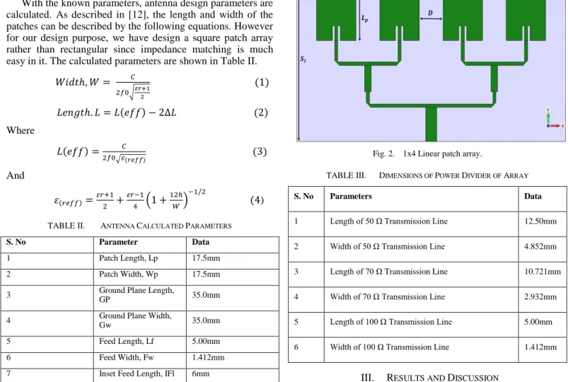
The array is composed of four identical square patches separated by half wavelength distance of 28mm as shown in Fig. 2. The Sl and Sw length and widths of Roggers 5880 are taken 50mm and 70mm respectively. The overall dimension of array is 3500mm2.
For power splitting network in an array system, power divider as corporate feed system plays a key role. It simply splits power the between “n” numbers of outputs ports with a certain distribution.
For impedance matching purposes, maximum power transfer theorem is used. Using quarter transformer, the 100 Ω transmission lines are matched to 70.7 Ω transmission line which are again splitted to 100 Ω and finally to inset feed of 50 Ω. Dimensions of power divider are shown in Table III.
Fig. 2. 1x4 Linear patch array.
TABLE III. DIMENSIONS OF POWER DIVIDER OF ARRAY
S. No Parameters Data
1 Length of 50 Ω Transmission Line 12.50mm 2 Width of 50 Ω Transmission Line 4.852mm 3 Length of 70 Ω Transmission Line 10.721mm 4 Width of 70 Ω Transmission Line 2.932mm 5 Length of 100 Ω Transmission Line 5.00mm 6 Width of 100 Ω Transmission Line 1.412mm
III. RESULTS AND DISCUSSION
The array was designed in Computer simulation Technology 2014. The array showed good performance parameters and an excellent impedance matching. The results are summarized in Table IV.
TABLE IV. PERFORMANCE PARAMETERS OF ANTENNA ARRAY Parameters Conventional Proposed
Return Loss -12.25dB -20.0dB Gain 7.18dB 12.82dB Directivity 7.15dBi 12.96dBi VSWR 1.05 1.034 Bandwidth 200MHz 245MHz
The return loss plot is shown in Fig. 3. The antenna showed good reflection co efficient of -20dB with satisfactory bandwidth of 245MHz. As compared to single element proposed array is well matched with power divider corporate feed.
(IJACSA) International Journal of Advanced Computer Science and Applications, Vol. 9, No. 4, 2018
119 | P a g e www.ijacsa.thesai.org
Fig. 3. S parameters of proposed antenna array.
The E and H plane polar pattern fields of our proposed 1x4 linear array are shown in Fig. 4 and directivity graph in both E plane and H plane is shown in Fig. 5.
Fig. 4. E field and H field polar pattern of linear array.
Fig. 5. E and H plane directivity plot.
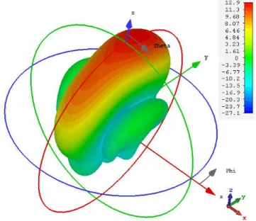
Fig. 6. 3 Dimensional plot of directivity.
In H field polar pattern, the main lobe direction is 0.0 deg with angular width of 24.3deg and side lobe level of-12.9dB while in E plane, the main lobe direction is 11.0 deg with angular width of 77.6deg and side lobe level of -15.8deg. The antenna showed broad sided direction of 12.9dB of directivity with high gain of 12.82dB. The percentage bandwidth of proposed linear array is 4.82%. The directivity 3D graph is shown in Fig. 6.
IV. CONCLUSION
In this paper, a square patch linear 1x4 array of 5.5GHz is proposed. A single element was designed and its results were compared to that of linear array results. The antenna array is composed by four antenna elements fed with the parallel method that allows the exciting signal to reach equally each element. The structure is implemented over Roggers 5880 substrate with 2.3 as relative permittivity, 1.575 mm for thickness and 0.0009 for loss tangent. It was found that with addition in patch elements, proposed array showed better performance results. With higher bandwidth and gain, the proposed array can be used for Short Range Radio Location and Short Range Radio Services applications.
V. FUTURE WORK
In future, this linear array can be tested with increased size of patch elements. Furthermore, the proposed patch array structure can de designed with 2x2 array configuration and same technique can be implemented through aperture coupled feed network.
REFERENCES
[1] Wang, H., X. B. Huang, and D. G. Fang. "A single layer wideband U-slot microstrip patch antenna array." IEEE antennas and wireless propagation letters 7 (2008): 9-12.
[2] Qian, Y., Coccioli, R., Sievenpiper, D., Radisic, V., Yablonovitch, E., & Itoh, T. (1999). A microstrip patch antenna using novel photonic band-gap structures. Microwave Journal, 42(1), 66-72.
[3] Kiani, S. H., Mahmood, K., Khattak, U. F., Burhan-Ud-Din, & Munir, M. (2016). U Patch Antenna using Variable Substrates for Wireless
(IJACSA) International Journal of Advanced Computer Science and Applications, Vol. 9, No. 4, 2018
120 | P a g e www.ijacsa.thesai.org
Communication Systems. International Journal of Advanced Computer Science and Applications, 7(12), 286-291.
[4] Kiani, S. H., Mahmood, K., Munir, M., & Cole, A. J. (2017). A Novel Design of Patch Antenna using U-Slot and Defected Ground Structure. INTERNATIONAL JOURNAL OF ADVANCED COMPUTER
SCIENCE AND APPLICATIONS, 8(3), 17-20.
[5] Salonen, P., Kim, J., & Rahmat-Samii, Y. (2005, July). Dual-band E-shaped patch wearable textile antenna. In Antennas and propagation society international symposium, 2005 IEEE (Vol. 1, pp. 466-469). IEEE.
[6] Zhang, Huiying, et al. "Miniaturized implantable antenna integrated with split resonate rings for wireless power transfer and data telemetry." Microwave and Optical Technology Letters 59.3 (2017): 710-714. [7] George, Jemima Nissiyah, and M. Ganesh Madhan. "Analysis of single
band and dual band graphene based patch antenna for terahertz region." Physica E: Low-dimensional Systems and Nanostructures 94 (2017): 126-131.
[8] Singh, Gurdeep, and Jaget Singh. "Comparative analysis of microstrip patch antenna with different feeding techniques." International Conference on Recent Advances and Future Trends in Information Technology, iRAFIT. 2012.
[9] Veeramani. A, Afsane Saee Arezomand, Vijayakrishnan. J, Ferdows B. Zarrabi, “Compact S-shaped EBG Structures for Reduction of Mutual Coupling,” 2015 Fifth International Conference on Advanced Computing & Communication Technologies, 2015.
[10] Altaf, Ahsan, M. A. Alsunaidi, and Ercument Arvas. "A novel EBG structure to improve isolation in MIMO antenna." USNC-URSI Radio Science Meeting (Joint with AP-S Symposium), 2017. IEEE, 2017. [11] Tu, D. T. T., Van Hoc, N., Quan, H., & Van Yem, V. (2016, July).
Compact MIMO antenna with low mutual coupling using defected ground structure. In Communications and Electronics (ICCE), 2016 IEEE Sixth International Conference on (pp. 242-247). IEEE.
[12] Balanis, Constantine A. Antenna theory: analysis and design. John Wiley & Sons, 2016.