The electronic and optical properties of an exciton, biexciton
and charged excitons in CdSe/CdTe‑based multi‑shell type‑II quantum
dot nanocrystals
Fatih Koç1,2 · Mehmet Sahin3
Received: 22 April 2019 / Accepted: 6 September 2019 / Published online: 17 September 2019 © Springer-Verlag GmbH Germany, part of Springer Nature 2019
Abstract
It has been recently reported that multi-shell type-II quantum dot nanocrystals (QDNCs) have higher quantum yields. Besides these higher quantum yields of multi-shell type-II QDNCs, additional second layer has been a critical influence on the formation mechanisms of the excitonic structures. Understanding of bound and unbound cases of the excitonic structures in multi-shell type-II QDNCs gives some important information for applications. In this study, we have investigated the
electronic and optical properties of a single exciton (X), biexciton (XX), and positively and negatively charged excitons ( 𝖷+
and 𝖷− ) in CdSe/CdTe-based multi-shell type-II QDNCs. In the study, three different structure compositions, i.e., CdSe/
CdTe, CdSe/CdTe/CdS, and CdSe/CdTe/ZnTe, have been considered. We have observed that CdS and ZnTe materials have drastically changed the electronic and optical properties of the bare CdSe/CdTe type-II QDNCs.
1 Introduction
The latest developments in crystal growth techniques has made possible to produce multi-shell quantum dot
nanocrys-tals (QDNCs) with control of the electronic properties [1–4].
Quantum dot nanocrystals, because of this tunability of the electronic properties depending on their size and/or mate-rial, are unique candidates to fabricate of the quantum dot
lasers [5–8], biological imaging devices [9–11], quantum dot
light-emitting diodes (LED) [12–15], photovoltaic [16–22]
and spintronics [24] applications. As well known, if both
carriers (i.e., electron and hole) are confined into the same spatial region of a QDNC, this structure is called as a type-I QD heterostructure. On the other hand, if the carriers are
confined in different spatial regions of a core/shell QDNC, this one is termed as type-II QDNC. The confinement type of QDNCs is dependent directly on their material proper-ties. Each structure has different physical properties and superiorities for different device applications. For exam-ple, while type-I QDNCs are appropriate for LED devices, type-II QDNCs are proper for photovoltaic devices such as solar cells. On the other hand, multi-shell type-II QDNCs can bring a new perspective to type-II QDNCs for the LED
applications [25].
In type-II structures, while the energy levels of the elec-tron and hole can be tuned separately by adjusting the core
size or shell thickness [27–30], this kind of controlling is not
possible in type-I heterostructures [31]. Therefore, this
con-trollability of the electronic structures of type-II QDNCs has distinct superiority when compared to that of type-I counter-parts. Similarly, the exciton lifetime can also be tuned much
more effectively in type-II QDNC heterostructures [32]. In
addition, when the core and shell materials are replaced with each other, confinement regions of the electron and hole replace by one another and so the electronic and opti-cal properties can largely become different. As well as many advantages of type-II QDNCs, these structures have a bad reputation owing to their low quantum yields at the same time. But it seems that multi-shell type-II QDNCs can be overcome this bad reputation thanks to their high quantum
yields [25, 31, 33].
* Mehmet Sahin
[email protected]; [email protected] Fatih Koç
1 Department of Physics, Faculty of Sciences, Selcuk University, 42075 Konya, Turkey
2 Department of Vocational School of Health Services, Igdir University, Igdir, Turkey
3 Department of Materials Science and Nanotechnology Engineering, School of Engineering, Abdullah Gül University, Sümer Campus, 38080 Kayseri, Turkey
F. Koç, M. Sahin
705 Page 2 of 9
The type-II structures are the subject of a great interest
both theoretically [29, 30, 34–36] and experimentally [19,
27, 31, 37–50] due to these outstanding properties.
Espe-cially, CdSe/CdTe type-II QDs are very promising struc-tures for photovoltaic applications and there are some studies
related to these structures in the literature [20, 52].
Leontia-dou et al. [52] investigated effect of the shell thickness on
the efficiency of CdSe/CdTe QD solar cells. In addition, they examined the exciton lifetime as a function of shell thickness in the same structures.
Although there are a number of experimental studies reported on the excitons in type-II QDNCs in the literature as well as theoretical ones, the studies on charged excitons and biexcitons in the type-II QDNCs are still unsatisfying. Understanding in details of charged excitons and biexci-tons in the type-II QDNCs is crucial for device fabrication, especially photovoltaic devices. For example, the electronic structure of a type-II core/shell QDNC can be substantially changed when an additional second layer covers onto the shell layer of the QDNC.
In our previous study, we investigated the effect of a buffer layer on the electronic and optical properties of an
X and XX in type-II CdTe/CdSe QDNCs. As mentioned
above, the electronic properties of a type-II QDNC can be substantially changed when the core and shell materials are switched their places. Therefore, in this work, we consider CdSe/CdTe QDNC and its derivatives. In this context, the primary goal of this study is to investigate the electronic and optical properties of exciton (X), biexciton (XX) and
positively and negatively charged excitons ( 𝖷+ and 𝖷− )
in type-II CdSe/CdTe, CdSe/CdTe/CdS, and CdSe/CdTe/ ZnTe QDNCs. To determine the electronic properties of the considered structures, i.e., energy levels and correspond-ing wavefunctions, the Poisson–Schrödcorrespond-inger equations have
been solved self-consistently in the Hartree approximation. Using these energy levels and wavefunctions, the optical properties, such as overlap integral, absorption wavelength,
oscillator strength, lifetime, of the X, XX, 𝖷+ and 𝖷− in
type-II CdSe/CdTe have been carried out for cases with and without different second layer materials, CdS and ZnTe. The obtained results and their possible physical reasons have been discussed in a detail manner.
2 Model and theory
We have considered a spherically symmetric type-II CdSe/ CdTe/organic coating (i.e., core/shell/ligand) QDNC and its derivatives in which a second shell is covered between shell and ligand, i.e., CdSe/CdTe/CdS/ligand and CdSe/CdTe/ ZnTe/ligand. The potential profile of CdSe/CdTe/CdS and
CdSe/CdTe/ZnTe structures are demonstrated in Fig. 1.
In frame of the envelope function effective mass
approxi-mation and BenDaniel–Duke boundary condition [26],
sin-gle-particle Schrödinger equations for multi excitons can be written as: and (1) [ −� 2 2 ⃗ ∇r ( 1 m∗ e(r) ⃗ ∇r ) +Ve(r) − qe𝜙h+qe𝜙e+Vxce−e[𝜌e(r)] ] Rse(r) = 𝜀eRse(r), (2) [ −� 2 2∇⃗r ( 1 m∗ h(r) ⃗ ∇r ) +Vh(r) − qh𝜙e+qh𝜙h+Vxch−h[𝜌h(r)] ] Rsh(r) = 𝜀hRsh(r),
Fig. 1 Schematic representation of the potential profiles of the con-sidered type-II structures for bare CdSe/CdTe QDNC (left panel), CdSe/CdTe/CdS QDNC (middle panel), and CdSe/CdTe/ZnTe
QDNC (right panel). Black and red circles show the electrons and holes, respectively. Dashed lines demonstrate the single-particle energy levels of the electrons and holes
where ℏ is the reduced Planck’s constant, m∗
e(r) and m
∗
h(r) are
the position-dependent electron and hole effective masses,
respectively, Ve(r) and Vh(r) are the electron and hole
con-finement potentials, respectively, qe is the electron and qh is
the hole charges. The 𝜙e and 𝜙h are the electrostatic
Cou-lomb potential due to the electron and hole, respectively.
The qe(h)𝜙h(e) is the attractive Coulomb potential between the
opposite charges and the qe(h)𝜙e(h) is the repulsive Coulomb
potential between the same kinds of particles. The Vxc[𝜌(r)]
terms are the exchange-correlation (XC) potentials between
the same signed particles, 𝜀e is single-particle energy
eigen-value of the electron and similarly, 𝜀h is single-particle hole
energy, and Rs
e(r) and R
s
h(r) are the s-type radial wave
func-tions of these energy states, respectively. It is noted that, in single-exciton cases, the repulsive Coulomb and XC poten-tial terms are not taken into consideration.
These two equations are coupled with each other through
the attractive Coulomb terms, qe𝜙h and qh𝜙e . To find the
single-particle energy levels of electron and hole, Eqs. (1)
and (2) are solved self-consistently and simultaneously. On
the other hand, if the QDNC contains more than one same kind of particle, in this case, the repulsive potentials between of them are computed self-consistently. Hence, all Coulomb effects on the energy eigenvalues and corresponding wave functions have been taken into account. The Coulomb poten-tials are calculated by solving of the Poisson equations:
where 𝜌e is electron and 𝜌h is hole densities [53], 𝜀0 is
die-lectric permittivity of the vacuum and 𝜅(r) is the position-dependent dielectric constant of the structure. These equa-tions contain the image potential contribuequa-tions originated from difference dielectric values of core and shell materials.
In calculation of the XC potential between the same particles, i.e., charged excitons and biexciton cases,
Per-dew-Zunger [54] expression, which is a parametrization
of the Monte Carlo results of Ceperley and Alder [55], is
employed. This expression of the XC potential contains the self-interaction corrections. In the case of strong confine-ment regime, it has been reported that electron–hole cor-relation energy can be negligible level relative to the
elec-tron–hole Coulomb energy [23]. Therefore, this energy term
has not been included in our calculations.
To determine the electronic structure of the considered
system, the last three equations, Eqs.(1), (2), and (3), must
be computed self-consistently. For this purpose, in the real space formalism, the full numeric matrix diagonalization technique can be used. All details of the computation steps
can be found in Ref. [29].
(3) ⃗ ∇𝜅(r) ⃗∇𝜙e=qe 𝜀0𝜌e(r), ⃗ ∇𝜅(r) ⃗∇𝜙h= −qh 𝜀0𝜌h(r),
The binding energy of the 𝖷+ , 𝖷− and XX can be
calcu-lated by means of [56]
where 𝜀(0)
e,h is isolated single electron (hole) energy in the
structures. Etot
𝖷 is the single exciton, E
tot
𝖷+ is the positively
and Etot
𝖷− is the negatively charged excitons and E
tot
𝖷𝖷 is the
biexciton total energies and these energies discussed in detail
in our previous work [51].
The oscillator strength, a measure of the optical transi-tions, is crucial parameter in studying of all optical proper-ties of any quantum structures from atoms to solids. The
single-exciton oscillator strength is given as [57]:
where Ep is the Kane energy, E𝖷 is the exciton transition
energy, Re(r) and Rh(r) are the radial part of electron and
hole wavefunctions, respectively.
The recombination oscillator strengths of the 𝖷+ , 𝖷− or
XX are calculated by means of
where E𝖷+,𝖷−
or𝖷𝖷 is the transition energy of the considered
system ( 𝖷+
, 𝖷− or 𝖷𝖷 ), and R
e(r) and Rh(r) are the
corre-sponding radial wavefunction of the electron and hole. Here,
A is a recombination probability of the system and the factor
A ≃2 for the bound and A = 1 for the unbound 𝖷+ and 𝖷− .
On the other hand, the factor A ≃ 4 for the bound and A ≃ 2 for the unbound XX. The details of this approximation can
be found in Ref. [28].
The radiative lifetime is another important quantity in both theoretical and experimental investigation of the
exci-tonic structures [27, 58–60]. The mathematical expression
of the radiative lifetime is given as [61, 62]:
where 𝜀0 is the dielectric permittivity of the vacuum, m0 is
the free electron mass, c is the light velocity in the vacuum,
e is the bare electronic charge, f is the oscillator strength, n
is the refractive index of QDNC material, E is the transition
energy of considered system and 𝛽s is the screening factor
[62]. (4) E𝖷+ b =E tot 𝖷 +𝜀 (0) h −E tot 𝖷+, E𝖷− b =E tot 𝖷 +𝜀 (0) e −E tot 𝖷−, Eb𝖷𝖷=Etot𝖷𝖷−2Etot 𝖷, (5) f𝖷= Ep 2E𝖷||||∫ r 2drRs e(r)R s h(r)|||| 2 , (6) f𝖷+ ,𝖷− or𝖷𝖷=A Ep 2E𝖷+ ,𝖷− or𝖷𝖷 || ||∫ r2drRe(r)Rh(r)|| || 2 , (7) 𝜏 = 6𝜋𝜀0m0c 3ℏ2 e2n𝛽 sE2f ,
F. Koç, M. Sahin
705 Page 4 of 9
3 Results and discussion
The atomic units are used throughout the calculations. In
this units, the Planck constant, ℏ , bare electron mass m0 , and
fundamental electronic charge e are equal to unity. All
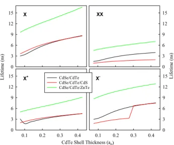
mate-rial parameters used in the calculations are listed in Table 1.
The effective exciton Bohr radius and the effective Rydberg
energy are a0=71.06 Å and Ry=9.74 meV , respectively,
in terms of the CdSe material parameters. In all structures,
the core radius has been set to Rc=1.95 nm.
The potential profile of the considered structures are
shown in Fig. 1. In these structures, CdS and ZnTe are
cho-sen as the second shell layers and thicknesses of them are
fixed to 0.1 a0 in the calculations. In left panel of the
fig-ure, while the electron(s) are substantially confined into the CdSe core region, hole(s) are confined into the CdTe shell of CdSe/CdTe QDNC. In middle panel of the figure, it is seen that a third material, i.e., CdS, is grown between shell and ligand as if a buffer layer. In right panel of the figure, the CdS layer is replaced by ZnTe. Thereby, the potential profile is modified and it is expected that the modification, in middle panel, will be effective especially on the energy level of electron(s) while the modification in right panel will especially affect the energy level of the hole(s).
The position-dependent effective masses and dielectric constants are given as:
Figure 2 depicts changes of the total energies of the X,
XX, 𝖷+ , and 𝖷− in CdSe/CdTe, CdSe/CdTe/CdS, CdSe/
CdTe/ZnTe QDNCs as a function of the CdTe shell thick-ness. The total energies of all structures, as expected,
(8) m∗ e,h(r) = ⎧ ⎪ ⎪ ⎨ ⎪ ⎪ ⎩ m∗ e,h(CdSe), r≤ RC m∗ e,h(CdTe), RC< r≤ RS m∗ e,h(buff), RS< r≤ RB m∗ e,h(lig), r > RB , 𝜅(r) = ⎧ ⎪ ⎨ ⎪ ⎩ 𝜅(CdSe), r≤ RC 𝜅(CdTe), RC< r≤ RS 𝜅(buff), RS< r≤ RB 𝜅(lig), r > RB .
decrease with increasing shell thickness and this decreas-ing is more distinctly in CdSe/CdTe and CdSe/CdTe/CdS QDNCs while it is not so dramatic in CdSe/CdTe/ZnTe QDNC. When we look at the potential profile, we conclude that, in the first and second structures, changing of the shell region affects directly the energy level of the hole(s) since the hole(s) are confined into the CdTe shell. Therefore, the total energy changing interval with respect to shell thick-ness is the most in CdSe/CdTe structures for all exciton complexes. However, although it is not very obvious, the electron(s) energy levels are affected from changing of the shell region thickness depending on the penetration of the electron wave functions into the shell region. In the third
structure, right panel of Fig. 1, confinement of the hole(s)
will most probably be inside the ZnTe shell depending on the CdTe shell thickness. For that reason, neither electron(s) nor hole(s) energy states are affected drastically from chang-ing of the shell thickness. On the other hand, the attractive Coulomb interaction will decrease with increasing shell thicknesses.
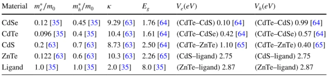
Binding energies of excitonic structures are other impor-tant quantities. Origin of the binding energy is the attrac-tive Coulomb potential between the electron(s) and hole(s). If a single exciton is unbound, the electron and hole move
Table 1 The material parameters used in the calculations
Material m∗
e∕m0 m ∗
h∕m0 𝜅 Eg Ve(eV) Vh(eV)
CdSe 0.12 [35] 0.45 [35] 9.29 [63] 1.76 [64] (CdTe–CdS) 0.10 [64] (CdTe–CdS) 0.99 [64] CdTe 0.096 [35] 0.4 [35] 10.4 [63] 1.61 [64] (CdTe–CdSe) 0.42 [64] (CdTe–CdSe) 0.57 [64] CdS 0.2 [63] 0.7 [63] 8.73 [63] 2.50 [64] (CdTe–ZnTe) 1.10 [65] (CdTe–ZnTe) 0.40 [65] ZnTe 0.122 [63] 0.6 [63] 10.3 [63] 2.26 [65] (CdS–ligand) 2.75 (CdS–ligand) 2.75 Ligand 1.0 [35] 1.0 [35] 2.0 [35] 8.0 [35] (ZnTe–ligand) 2.87 (ZnTe–ligand) 2.87
X 1.5 1.8 2.1 2.4 2.7 3.0 X+
CdTe Shell Thickness (a0)
0.1 0.2 0.3 0.4 Energy (eV) 1.5 1.8 2.1 2.4 2.7 3.0 X -0.1 0.2 0.3 0.4 Energy (eV) 1.5 1.8 2.1 2.4 2.7 3.0 XX 1.5 1.8 2.1 2.4 2.7 3.0 CdSe/CdTe CdSe/CdTe/CdS CdSe/CdTe/ZnTe
Fig. 2 Total energy of the X, XX (top panel) and 𝖷+ , 𝖷− (bottom panel) as a function of the CdTe shell thicknesses for three different QDNC structures
independently from each other and hence, these carriers can be separated relatively easily and in this case, there is no an exciton in exact manner. Actually, there is just an electron–hole pair. However, in semiconductor quantum nanostructures, especially in quantum dots, single excitons are in bound forms. As for trions, bound trion term cor-responds to a situation in which all particles behave as a single particle. Namely, the attractive Coulomb potential is more dominant than repulsive interactions between the same charges. In case of an unbound trion, the repulsive Coulomb potential is dominant and this structure is dealt
as an exciton and an excess charge, that is an electron in 𝖷−
and a hole in 𝖷+ . Similarly, in an XX structure, if the
attrac-tive Coulomb potential between the electrons and holes is higher, all of the charges move as a single particle and are called as a bound biexciton. In an unbound biexciton case, the repulsive Coulomb potential is stronger and this structure
can be considered as two independent excitons [28]. The
unbound excitonic structures are more proper for photovol-taic applications when compared to the bound excitons. Con-versely, bound excitonic structures, observed especially in type-I QDNC, are more appropriate for illumination devices
such as, LED. Figure 3 demonstrates the binding energies
of the X, XX, 𝖷+ , and 𝖷− in CdSe/CdTe, CdSe/CdTe/CdS,
and CdSe/CdTe/ZnTe QDNCs as a function of the CdTe shell thicknesses. When we look at the binding energy of the
X, we see that the changing of it in CdSe/CdTe exhibits a
typical exciton-binding energy behavior. That is, it decreases with increasing shell thickness. And also the highest exciton binding energy value is observed again in this QDNC. This can be explained as follows: in smaller shell thicknesses, the hole pushes towards the core region and so the attrac-tive Coulomb interaction becomes higher due to smaller
distance between the electron and hole and with increas-ing shell thickness this attractive Coulomb energy becomes smaller because of the larger distance between the electron and hole. Yet, in other two QDNCs with CdS and ZnTe additional shells, the binding energy values are smaller and especially in CdSe/CdTe/CdS QDNC, the binding energy value is almost unchanging with increasing shell thickness. This is because the probability distribution of the electron expands to whole structure and hence, the Coulomb interac-tion becomes approximately constant. In CdSe/CdTe/ZnTe QDNC, since the hole is substantially confined into the ZnTe shell, the attractive Coulomb interaction is decreasing with increasing shell thickness for the exciton. When we look at the XX panel, we see that this structure is unbound in bare CdSe/CdTe QDNC and its derivative with ZnTe layer. Its reason is that the repulsive Coulomb interaction between the charges with the same sign is predominant when compared to the attractive Coulomb interactions between the electrons and holes. On the other hand, in CdSe/CdTe/CdS QDNC, the attractive Coulomb interaction is more dominant and so a bound XX structure emerges. This result is so crucial in terms of demonstrating that controlling of the binding situ-ations of the XX depending on the second shell material.
As for the 𝖷+ and 𝖷− structures, while positively charged
exciton is bound in all three QDNCs (except shell thickness
of 0.075 a0 for CdSe/CdTe QDNC), negatively charged
exci-ton is unbound in CdSe/CdTe and CdSe/CdTe/ZnTe QDNCs and it is bound until a certain value of the shell thickness in
CdSe/CdTe/CdS QDNC. It can be concluded that, in the 𝖷+ ,
the attractive Coulomb interactions are larger. On the other
hand, in the 𝖷− , the repulsive Coulomb interactions are more
dominant in case of unbound situations.
The absorption wavelength, which corresponds to the transition energy, is another important parameter of the
QDNCs for device applications of these structures. Figure 4
shows the changes of the absorption wavelengths for the
X and XX (top panel), and 𝖷+ and 𝖷− (bottom panel) as a
function of the CdTe layer thickness. As seen from the fig-ures, in all structfig-ures, the absorption wavelengths increase (red shift) with increasing of the shell thicknesses. This behavior is an expected situation since the energy levels are inverse proportional to the size of the quantum structures. Yet, the interesting situation for the exciton is while chang-ing intervals are approximately between 575 and 780 nm in CdSe/CdTe and CdSe/CdTe/CdS QDNCs, this interval is very narrow, between 600 and 650 nm, in CdSe/CdTe/ ZnTe QDNC. Similar observation in CdSe/CdTe QDNCs
has been reported by Leontiadou et al. [52]. In their study,
when the shell thickness is smaller than 0.5 nm, the structure exhibits quasi-type-II (or type-I) properties. In this study, the shell thickness starts almost from 0.5 nm, and, therefore, the quasi-type-II regime is not so apparent for the X structure. Another observation is that the absorption wavelength of X -50 0 50 100 150 X+
CdTe Shell Thickness (a0)
0.1 0.2 0.3 0.4 Bi nding en ergy (m eV ) -50 0 50 100 150 X -0.1 0.2 0.3 0.4 Bi nding en ergy (m eV ) -50 0 50 100 150 XX -50 0 50 100 150 CdSe/CdTe CdSe/CdTe/CdS CdSe/CdTe/ZnTe
Fig. 3 Binding energy of the X, XX (top panel) and 𝖷+ , 𝖷− (bottom panel) as a function of the CdTe shell thicknesses for three different QDNC structures
F. Koç, M. Sahin
705 Page 6 of 9
the X is beginning from lower than 650 nm in CdSe/CdTe/ CdS QDNC while the absorption wavelength of the other excitonic complexes starts from higher than 650 nm, it is
almost 700 nm for 𝖷+ and XX. Overall observation is that the
absorption wavelengths are strongly dependent on the CdTe shell thickness in all QDNCs except for CdSe/CdTe/ZnTe QDNC. This is because the hole(s) are confined to the CdTe shell region in first two structures. On the other hand, in the third structure, the hole(s) are substantially confined into ZnTe layer and the thickness changing of the shell region does not affect dramatically the absorption wavelength of QDNC with the ZnTe shell.
The overlap integral is a unitless quantity and it is key in calculation of the oscillator strength. This important parameter gives an information about the overlapping of the
electron and hole wavefunctions. Figure 5 demonstrates the
overlap integral of all excitonic complexes in QDNCs. In overall glance, we see that the overlap integral of all X, XX,
𝖷+ , and 𝖷− is approximately unity when the shell thickness
is very small in CdSe/CdTe and CdSe/CdTe/CdS QDNCs and it decreases with increasing shell thicknesses. This is because when the shell thicknesses are smaller, the hole(s), due to the pushing to core region, are localized almost in the same spatial region with the electron(s). This localiza-tion of the hole wavefunclocaliza-tion disappear with increasing shell thicknesses and consequently the overlap becomes weaker. Nevertheless, in CdSe/CdTe/ZnTe QDNC, the hole(s) are considerably confined into the ZnTe layer due to the lower potential and hence, the overlap of wavefunctions is already smaller and is not affected drastically from the changing of the shell thicknesses.
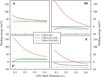
The oscillator strength is a dimensionless quantity and it can be considered as the probability of absorption or
emission of light in optical transitions of a quantum
mechan-ical system. Figure 6 shows the radiative recombination
oscillator strengths (ROS) of the X, XX, 𝖷+ , and 𝖷− as a
function of the CdTe shell thickness. The ROS values of the
X, XX, 𝖷+ , and 𝖷− are minimum in QDNC with the ZnTe
layer. This is because the overlap integrals of CdSe/CdTe/ ZnTe QDNCs are smaller for all exciton structures. In CdSe/ CdTe and CdSe/CdTe/CdS QDNCs, changing of the ROS of
the X and 𝖷+ are very similar to each other. When the shell
thickness is very small (0.075 a0 ), the ROS of 𝖷
+ in CdSe/
CdTe QDNC becomes smaller because the 𝖷+ is unbound
at this thickness value. As known, if there are two exciton structures in a QDNC, they can form a biexciton (bound X 600 650 700 750 800 XX 600 650 700 750 800 X+
CdTe Shell Thickness (a0)
0.1 0.2 0.3 0.4 Absorption Wa velength (n m) 600 650 700 750 800 X -0.1 0.2 0.3 0.4 Absorption Wa velength (n m) 600 650 700 750 800 CdSe/CdTe CdSe/CdTe/CdS CdSe/CdTe/ZnTe
Fig. 4 Absorption wavelength of the X, XX (top panel) and 𝖷+ , 𝖷− (bottom panel) as a function of the CdTe shell thicknesses for three different QDNC structures X 0.0 0.2 0.4 0.6 0.8 1.0 X+
CdTe Shell Thickness (a0)
0.1 0.2 0.3 0.4 Overla p 0.0 0.2 0.4 0.6 0.8 1.0 X -0.1 0.2 0.3 0.4 Overl ap 0.0 0.2 0.4 0.6 0.8 1.0 XX 0.0 0.2 0.4 0.6 0.8 1.0 CdSe/CdTe CdSe/CdTe/CdS CdSe/CdTe/ZnTe
Fig. 5 Overlap integral of the X, XX (top panel) and 𝖷+ , 𝖷−
(bottom panel) as a function of the CdTe shell thicknesses for three different QDNC structures X 0 5 10 15 X+
CdTe Shell Thickness (a0)
0.1 0.2 0.3 0.4 Osci llator Streng th 0 5 10 15 X -0.1 0.2 0.3 0.4 Osci llator Streng th 0 5 10 15 CdSe/CdTe CdSe/CdTe/CdS CdSe/CdTe/ZnTe XX 0 5 10 15
Fig. 6 Oscillator strength of the X, XX (top panel) and 𝖷+ , 𝖷−
(bot-tom panel) as a function of the CdTe shell thicknesses for three differ-ent QDNC structures
structure) or two independent excitons, called unbound biex-citon, depending on the interaction between X and X. Similar
explanations can be done for 𝖷+ and 𝖷− structures. Hence,
the factor A in Eq. (6) takes different values for the bound
and unbound cases. In the unbound case of 𝖷+ or 𝖷− , as
mentioned in model and theory section, the factor A is unity and it becomes two in the bound cases. Similarly, the fac-tor A is two for the unbound biexciton cases while it is four for the bound biexcitons. Variations of the ROS of the XX
and 𝖷− are similar to each other until shell thickness is 0.3
a0 . At this thickness value, 𝖷− in CdSe/CdTe/CdS QDNC
is unbound and so the oscillator strength becomes smaller suddenly due to changing of the factor A.
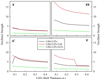
In investigation of the potential device application of the QDNCs, the radiative lifetime of the excitons is extremely important and, therefore, in almost all experimental stud-ies, the lifetime measurements have an extensive place. In
Fig. 7, the radiative lifetimes of the X, XX, 𝖷+ , and 𝖷− are
plotted as a function of the CdTe shell thickness. As can be seen from the figure, the lifetimes range from 2 to 20 ns. It is clearly seen that all exciton complexes have the long-est lifetime in the QDNC with the ZnTe additional shell. This is because the hole(s) are almost completely confined into the second shell. In other two QDNCs, CdTe/CdSe and CdTe/CdSe/CdS, the lifetime values are almost the same in
a wide region, especially in the X and 𝖷+ structures. On the
other hand, an apparent separation is observed between the
lifetime values of the XX and 𝖷− structures, depending on
whether they are bound or not. As can be seen from Eq.(7),
the lifetime is proportional inversely with the oscillator strength and its values are different for the bound or unbound
cases as explained in discussion of Fig.6. Therefore, these
changes in the oscillator strength will affect directly the radi-ative lifetimes. Hence, the lifetime of the bound XX becomes shorter when compared to its unbound counterpart. Similar
explanation is also valid for 𝖷+ and 𝖷− structures. In the
lit-erature, some experimental studies[66] related to the lifetime
of biexcitons and trions, in which radiative lifetime of the
XX and 𝖷+ is explained using similar model we proposed,
are available.
4 Conclusion
In this work, we have explored the electronic and optical
properties of the X, XX, 𝖷+ , and 𝖷− in CdSe/CdTe, CdSe/
CdTe/CdS, and CdSe/CdTe/ZnTe QDNCs in a detail. To carry out the electronic structure calculations, the Poisson and Schrödinger equations have been solved self-consist-ently in the Hartree approximation for all structures. The optical properties, absorption wavelengths, overlap integrals, oscillator strengths, and radiative lifetimes have been deter-mined using the obtained energy values and wavefunctions. We observe that all electronic and optical properties of the excitonic structures are strongly affected from potential pro-file and thickness of the additional second shell materials, CdS and ZnTe. This controllability provides a very impor-tant opportunity in terms of design of the type-II multi-shell QDNCs for some specific applications. It is hoped that this detailed investigation will give important informations to
scientists in understanding of the X, XX, 𝖷+ , and 𝖷−
struc-tures in multi-shell type-II QDNCs.
Acknowledgements This study was supported by TUBITAK TBAG
with project number 109T729. One of the authors (MS) thanks Abdul-lah Gul University Foundation (AGUV) for their partial financial support.
References
1. D. Bimberg, M. Grundmann, N.N. Ledentsov, Quantum dot het-erostructures (Wiley, Chichester, 1999)
2. V.I. Klimov, Nanocrystal Quantum Dots, 2nd edn. (CRC, Taylor and Francis Group, LLC, Boca Raton, 2010)
3. E.A. Dias, J.I. Saari, P. Tyagi, P. Kambhampati, Improving opti-cal gain performance in semiconductor quantum dots via coupled quantum shells. J. Phys. Chem. C 116, 5407–5413 (2012) 4. R.K. Ratnesh, M.S. Mehata, Synthesis and optical properties of
core-multi-shell CdSe/CdS/ZnS quantum dots: surface modifica-tions. Opt. Mater. 64, 250–256 (2017)
5. N. Kirstaedter, O.G. Schmidt, N.N. Ledentsov, D. Bimberg, Gain and differential gain of single layer InAs/GaAs quantum dot injec-tion lasers. Appl. Phys. Lett. 69, 1226–1228 (1996)
6. Y. Wang, V.D. Ta, Y. Gao, T.C. He, R. Chen, E. Mutlugun, H.V. Demir, H.D. Sun, Stimulated Emission and Lasing from CdSe/ CdS/ZnS core-multi-shell quantum dots by simultaneous three-photon absorption. Adv. Mater. 26, 2954–2961 (2014)
X 0 3 6 9 12 15 X+
CdTe Shell Thickness (a0)
0.1 0.2 0.3 0.4 Lifetim e (ns ) 0 3 6 9 12 15 X -0.1 0.2 0.3 0.4 Lifetim e (ns ) 0 3 6 9 12 15 XX 0 3 6 9 12 15 CdSe/CdTe CdSe/CdTe/CdS CdSe/CdTe/ZnTe
Fig. 7 Radiative lifetime of the X, XX (top panel) and 𝖷+ , 𝖷−
(bottom panel) as a function of the CdTe shell thicknesses for three different QDNC structures
F. Koç, M. Sahin
705 Page 8 of 9
7. F. Fan, O. Voznyy, R.P. Sabatini, K.T. Bicanic, M.M. Adachi, J.R. McBride, K.R. Reid, Young-Shin Park, X. Li, A. Jain, Rafael Quintero-Bermudez, M. Saravanapavanantham, M. Liu, M. Korkusinski, P. Hawrylak, V.I. Klimov, S.J. Rosenthal, S. Hoog-land, E.H. Sargent, Continuous-wave lasing in colloidal quantum dot solids enabled by facet-selective epitaxy. Nature 544, 75–79 (2017)
8. A.Y. Liu, J. Peters, X. Huang, D. Jung, J. Norman, M.L. Lee, A.C. Gossard, J.E. Bowers, Electrically pumped continuous-wave 1.3 𝜇 m quantum-dot lasers epitaxially grown on on-axis (001) GaP/ Si. Opt. Lett. 42, 338–341 (2017)
9. O.T. Bruns, T.S. Bischof, D.K. Harris, D. Franke, Y. Shi, L. Riedemann, A. Bartelt, F.B. Jaworski, J.A. Carr, C.J. Rowlands, M.W.B. Wilson, O. Chen, H. Wei, G.W. Hwang, D.M. Montana, I. Coropceanu, O.B. Achorn, J. Kloepper, J. Heeren, P.T.C. So, D. Fukumura, K.F. Jensen, R.K. Jain, M.G. Bawendi, Next-gen-eration in vivo optical imaging with short-wave infrared quantum dots. Nat. Biomed. Eng. 1, 0056 (2017)
10. Chi-Shiang Ke, Chia-Chia Fang, Jia-Ying Yan, J.R. Po-Jung Tseng, Chuan-Pin Chen Pyle, J. Shu-Yi Lin, X.Zhang Chen, Yang-Hsiang Chan, Molecular engineering and design of semiconduct-ing polymer dots with narrow-band, near-infrared emission for in vivo biological imaging. ACS Nano 11, 3166–3177 (2017).
https ://doi.org/10.1021/acsna no.7b002 15
11. I. Martinić, S.V. Eliseeva, S. Petoud, Near-infrared emitting probes for biological imaging: organic fluorophores, quantum dots, fluorescent proteins, lanthanide(III) complexes and nano-materials. J. Luminescence 189, 19–43 (2017)
12. P.O. Anikeeva, J.E. Halpert, M.G. Bawendi, V. Bulović, Quantum dot light-emitting devices with electroluminescence tunable over the entire visible spectrum. Nano Lett. 9, 2532–2536 (2009). https ://doi.org/10.1021/nl900 2969
13. K.T. Shimizu, M. Böhmer, D. Estrada, S. Gangwal, S. Grabowski, H. Bechtel, E. Kang, K.J. Vampola, D. Chamberlin, O.B. Shchekin, J. Bhardwaj, Toward commercial realization of quan-tum dot based white light-emitting diodes for general illumination. Photon. Res. 5, A1–A6 (2017)
14. G. Zaiats, S. Ikeda, S. Kinge, P.V. Kamat, Quantum dot light-emitting devices: beyond alignment of energy levels. ACS Appl. Mater. Interfaces 9, 30741–30745 (2017). https ://doi.org/10.1021/ acsam i.7b078 93
15. H.C. Yoon, J.H. Oh, S. Lee, J.B. Park, Y.R. Do, Circadian-tunable perovskite quantum dot-based down-converted multi-package white LED with a color fidelity index over 90. Sci. Rep. 7, 2808 (2017)
16. M.C. Beard, K.P. Knutsen, P. Yu, J.M. Luther, Q. Song, W.K. Metzger, R.J. Ellingson, A.J. Nozik, Multiple exciton generation in colloidal silicon nanocrystals. Nano Lett. 7, 2506–2512 (2007) 17. V.P. Kamat, Quantum dot solar cells, semiconductor nanocrystals
as light harvesters. J. Phys. Chem. C 112, 18737–18753 (2008) 18. J. Bang, J. Park, J.H. Lee, N. Won, J. Nam, J. Lim, J.B. Park,
ZnTe/ZnSe (core/shell) type-II quantum dots: their optical and photovoltaic properties. Chem. Mater. 22, 233–240 (2009) 19. C.M. Cirloganu, L.A. Padilha, Q. Lin, N.S. Makarov, K.A.
Velizhanin, H. Luo, I. Robel, J.M. Pietryga, V.I. Klimov, Enhanced carrier multiplication in engineered quasi-type-II quan-tum dots. Nat. Commun. 5, 4148 (2014). https ://doi.org/10.1038/ ncomm s5148
20. S. Tomic, J.M. Miloszewski, E.J. Tyrrell, D.J. Binks, Design of core/shell colloidal quantum dots for MEG solar cells. IEEE J. Photovolt. 6, 179–184 (2016)
21. M. Liu, O. Voznyy, R. Sabatini, F.P.G. de Arquer, R. Munir, A.H. Balawi, X. Lan, F. Fan, G. Walters, A.R. Kirmani, S. Hoogland, F. Laquai, A. Amassian, E.H. Sargent, Hybrid organic-inorganic inks flatten the energy landscape in colloidal quantum dot solids. Nat. Mater. 16, 258–263 (2017)
22. B. Sun, O. Voznyy, H. Tan, P. Stadler, M. Liu, G. Walters, A.H. Proppe, M. Liu, J. Fan, T. Zhuang, J. Li, M. Wei, J. Xu, Y. Kim, S. Hoogland, E.H. Sargent, Pseudohalide-exchanged quantum dot solids achieve record quantum efficiency in infra-red photovoltaics. Adv. Mater. 29, 1700749 (2017). https ://doi. org/10.1002/adma.20170 0749
23. A. Franceschetti, H. Fu, L.W. Wang, A. Zunger, Many-body pseudopotential theory of excitons in InP and CdSe quantum dots. Phys. Rev. B 60, 1819–1829 (1999)
24. M.C. Tamargo, I.L. Kuskovsky, C. Meriles, I.C. Noyan, Enhanced materials based on submonolayer type-II quantum dots (no. DOE-CCNY-0003739-1), Research Foundation of The City College of New York (2017)
25. X. Jin, H. Li, S. Huang, X. Gu, H. Shen, D. Li, X. Zhang, Q. Zhang, F. Li, Q. Li, Bright alloy type-II quantum dots and their application to light-emitting diodes. J. Colloid Interface Sci.
510, 376–383 (2018). https ://doi.org/10.1016/j.jcis.2017.09.080
26. D.J. BenDaniel, C.B. Duke, Space-charge effects on electron tunneling. Phys. Rev. 152, 683–692 (1966)
27. S.A. Ivanov, M. Achermann, Spectral and dynamic properties of excitons and biexcitons in type-II semiconductor nanocrystals. ACS Nano 4, 5994–6000 (2010)
28. M. Sahin, F. Koc, A model for the recombination and radiative lifetime of trions and biexcitons in spherically shaped semicon-ductor nanocrystals. Appl. Phys. Lett. 102, 183103 (2013) 29. F. Koç, M. Sahin, Electronic and optical properties of single
excitons and biexcitons in type-II quantum dot nanocrystals. J. Appl. Phys. 115, 193701 (2014)
30. F. Koç, K. Koksal, M. Sahin, Effect of a buffer layer between the shell and ligand on the optical properties of an exciton and biexciton in type-II quantum dot nanocrystals. Philos. Mag. 97, 201–211 (2016). https ://doi.org/10.1080/14786 435.2016.12528 61
31. S. Kim, B. Fisher, H.J. Eisler, M. Bawendi, Type-II Quantum Dots: CdTe/CdSe(Core/Shell) and CdSe/ZnTe(Core/Shell) Het-erostructures. J. Am. Chem. Soc. 125, 11466–11467 (2003) 32. F. Hatami, M. Grundmann, N.N. Ledentsov, F. Heinrichsdorff,
R. Heitz, J. Böhrer, D. Bimberg, S.S. Ruvimov, P. Werner, V.M. Ustinov, P.S. Kop’ev, ZhI Alferov, Carrier dynamics in type-II GaSb/GaAs quantum dots. Phys. Rev. B 57, 4635–4641 (1998) 33. C.M. Tyrakowski, A. Shamirian, C.E. Rowland, H. Shen, A. Das,
R.D. Schaller, P.T. Snee, Bright type II quantum dots. Chem. Mater. 27, 7276–7281 (2015)
34. A. Piryatinski, S.A. Ivanov, S. Tretiak, V.I. Klimov, Effect of quantum and dielectric confinement on the exciton-exciton inter-action energy in type II core/shell semiconductor nanocrystals. Nano Lett. 7, 108–115 (2007). https ://doi.org/10.1021/nl062 2404
35. E.J. Tyrrell, J.M. Smith, Effective mass modeling of excitons in type-II quantum dot heterostructures. Phys. Rev. B 84, 165328 (2011)
36. E.J. Tyrrell, S. Tomic, Effect of correlation and dielectric con-finement on 1S(e)
1∕2nS (h)
3∕2 excitons in CdTe/CdSe and CdSe/CdTe Type-II quantum dots. J. Phys. Chem. C 119, 12720–12730 (2015) 37. L.P. Balet, S.A. Ivanov, A. Piryatinski, M. Achermann, V.I.
Klimov, Inverted core/shell nanocrystals continuously tunable between type-I and type-II localization regimes. Nano Lett. 4, 1485–1488 (2004). https ://doi.org/10.1021/nl049 146c
38. J. Nanda, S.A. Ivanov, H. Htoon, I. Bezel, A. Piryatinski, S. Tre-tiak, V.I. Klimov, Absorption cross sections and Auger recombina-tion lifetimes in inverted core-shell nanocrystals: implicarecombina-tions for lasing performance. J. Appl. Phys. 99, 034309 (2006). https ://doi. org/10.1063/1.21680 32
39. J. Nanda, S.A. Ivanov, M. Achermann, I. Bezel, A. Piryatinski, V.I. Klimov, Light Amplification in the Single-Exciton Regime Using Exciton-Exciton Repulsion in Type-II Nanocrystal Quan-tum Dots. J. Phys. Chem. C 111, 15382–15390 (2007)
40. K. Matsuda, S.V. Nair, H.E. Ruda, Y. Sugimoto, T. Saiki, K. Yamaguchi, Two-exciton state in GaSb/GaAs type-II quantum dots studied using near-field photoluminescence spectroscopy. Appl. Phys. Lett. 90, 013101 (2007)
41. Dan Oron, Miri Kazes, Uri Banin, Multiexcitons in type-II colloi-dal semiconductor quantum dots. Phys. Rev. B 75, 035330 (2007) 42. V.I. Klimov, S.A. Ivanov, J. Nanda, M. Achermann, I. Bezel, J.A.
McGuire, A. Piryatinski, Single-exciton optical gain in semicon-ductor nanocrystals. Nature 447, 441–446 (2007)
43. R. Osovsky, D. Cheskis, V. Kloper, A. Sashchiuk, M. Kroner, E. Lifshitz, Continuous-wave pumping of multiexciton bands in the photoluminescence spectrum of a single CdTe-CdSe core-shell colloidal quantum dot. Phys. Rev. Lett. 102, 197401 (2009) 44. B. Bansal, S. Godefroo, M. Hayne, G. Medeiros-Ribeiro, V.V.
Moshchalkov, Extended excitons and compact heliumlike biexci-tons in type-II quantum dots. Phys. Rev. B 80, 205317 (2009) 45. D. Gachet, A. Avidan, I. Pinkas, D. Oron, An upper bound to
car-rier multiplication efficiency in type II colloidal quantum dots. Nano Lett. 10, 164–170 (2010). https ://doi.org/10.1021/nl903 172f
46. H. Zhu, N. Song, T. Lian, Wave function engineering for ultrafast charge separation and slow charge recombination in type II core/ shell quantum dots. J. Am. Chem. Soc. 133, 8762–8771 (2011).
https ://doi.org/10.1021/ja202 752s
47. B. Barman, R. Oszwałdowski, L. Schweidenback, A.H. Russ, J.M. Pientka, Y. Tsai, W.-C. Chou, W.C. Fan, J.R. Murphy, A.N. Cartwright, I.R. Sellers, A.G. Petukhov, I. Žutić, B.D. McCombe, A. Petrou, Time-resolved magnetophotoluminescence studies of magnetic polaron dynamics in type-II quantum dots. Phys. Rev. B 92, 035430 (2015)
48. Y. Jia, J. Chen, K. Wu, A. Kaledin, D.G. Musaev, Z. Xie, T. Lian, Enhancing photo-reduction quantum efficiency using quasi-type II core/shell quantum dots. Chem. Sci. 7, 4125–4133 (2016) 49. K. Komolibus, T. Piwonski, C.J. Reyner, B. Liang, G. Huyet,
D.L. Huffaker, E.A. Viktorov, J. Houlihan, Absorption dynam-ics of type-II GaSb/GaAs quantum dots. Opt. Mater. Express 7, 1424–1430 (2017)
50. P. Klenovský, P. Steindl, D. Geffroy, Excitonic structure and pumping power dependent emission blue-shift of type-II quantum dots. Sci. Rep. 7, 45568 (2017). https ://doi.org/10.1038/srep4 5568
51. A. Aktürk, M. Sahin, F. Koc, A. Erdinc, A detailed investigation of electronic and optical properties of the exciton, the biexciton and charged excitons in a multi-shell quantum dot nanocrystal. J. Phys. D Appl. Phys. 47, 285301 (2014)
52. M.A. Leontiadou, E.J. Tyrrell, C.T. Smith, D. Espinobarro-Velazquez, R. Page, P. O’Brien, J. Miloszewski, T. Walsh, D. Binks, S. Tomic, Influence of elevated radiative lifetime on effi-ciency of CdSe/CdTe Type II colloidal quantum dot based solar cells. Solar Energy Mater. Solar Cells 159, 657–663 (2017)
53. M. Sahin, S. Nizamoglu, O. Yerli, H.V. Demir, Reordering orbitals of semiconductor multi-shell quantum dot-quantum well hetero-nanocrystals. J. Appl. Phys. 111, 023713 (2012)
54. J.P. Perdew, A. Zunger, Self-interaction correction to density-functional approximations for many-electron systems. Phys. Rev. B 23, 5048–5079 (1981)
55. D.M. Ceperley, B.J. Alder, Ground State of the Electron Gas by a Stochastic Method. Phys. Rev. Lett. 45, 566–568 (1980) 56. T. Tsuchiya, Biexcitons and charged excitons in quantum dots: a
quantum monte carlo study. Phys. E 7, 470–474 (2000)
57. V.A. Fonoberov, A.A. Balandin, Excitonic properties of strained wurtzite and zinc-blende GaN/AlxGa1-xN/GaN/AlxGa1-xN quantum dots. J. Appl. Phys. 94, 7178 (2003)
58. M. Gong, W. Zhang, G.C. Guo, L. He, Atomistic pseudopoten-tial theory of optical properties of exciton complexes in InAs/InP quantum dots. Appl. Phys. Lett. 99, 231106 (2011)
59. P.P. Jha, Philippe Guyot-Sionnest, Trion decay in colloidal quan-tum dots. ACS Nano 3, 1011 (2009)
60. G.A. Narvaez, G. Bester, A. Zunger, Excitons, biexcitons, and trions in self-assembled (In, Ga)As/GaAs quantum dots: Recom-bination energies, polarization, and radiative lifetimes versus dot height. Phys. Rev. B 72, 245318 (2005)
61. M. Califano, A. Franceschetti, A. Zunger, Lifetime and polariza-tion of the radiative decay of excitons, biexcitons, and trions in CdSe nanocrystal quantum dots. Phys. Rev. B 75, 115401 (2007) 62. B. Alen, J. Bosch, D. Granados, J. Martinez-Pastor, J.M. Garcia, L. Gonzalez, Oscillator strength reduction induced by external electric fields in self-assembled quantum dots and rings. Phys. Rev. B 75, 045319 (2007)
63. O. Madelung, Semiconductors: data handbook (Springer, Heidel-berg, 2004)
64. Su-Huai Wei, S.B. Zhang, A. Zunger, First-principles calculation of band offsets, optical bowings, and defects in CdS, CdSe, CdTe, and their alloys. J. Appl. Phys. 87, 1304–1311 (2000)
65. C.Y. Chen, C.T. Cheng, C.W. Lai, Y.H. Hu, P.T. Chou, Y.H. Chou, H.T. Chiu, Type-II CdSe/CdTe/ZnTe (core-shell-shell) quantum dots with cascade band edges: the separation of electron (at CdSe) and hole (at ZnTe) by the CdTe layer. Small 1, 1215–1220 (2005) 66. A.F. Cihan, P.L. Hernandez Martinez, Y. Kelestemur, E. Mutlu-gun, H.V. Demir, Observation of biexcitons in nanocrystal solids in the presence of photocharging. ACS Nano 7, 4799–4809 (2013)
Publisher’s Note Springer Nature remains neutral with regard to jurisdictional claims in published maps and institutional affiliations.