Improvement for Fast Response of Current Sensorless
Model Control DC-DC Converter
Yudai Furukawa
1, Hidenori Maruta
1, Shingo Watanabe
1, Fujio Kurokawa
1, Nobumasa Matsui
2and Ilhami Colak
3 1Graduate School of Engineering, Nagasaki University, Nagasaki, Japane-mail: [email protected]
2Faculty of Engineering, Nagasaki Institute of Applied Science, Nagasaki, Japan
e-mail: [email protected]
3Faculty of Engineering and Architecture, Gelisim University, Istanbul, Turkey
e-mail: [email protected]
Abstract— The switching power supply is required the wide load range operation for the energy saving. In such a situation, the output voltage must be regulated. The model control is able to regulate the output voltage, because the bias value is varied depending on the static model equation. Thus, it is effective for switching power supply to implement the model control. The existing sensorless model cannot have a quick response. The purpose of this paper is to improve the transient response of the sensorless model control dc-dc converter by setting the parameter of the function that changes the operating point for a short time at the start of the transient state. It suppresses the undershoot of output voltage. The validity of the proposed method is confirmed by comparison with existing model control method and the proposed sensorless model method.
Keywords—dc-dc converter, sensorless model control
I. INTRODUCTION
The high performance power management system is required [1]-[4] since the information network society is widely developed and energy saving in the communication equipment becomes very important. Also, reliability and efficiency of the communication power supply are required to be high. Especially, in the power supply, the operation of the standby mode for the energy saving is important [5]. Thus, it must return to the active mode quickly and the output voltage must be kept to the reference voltage from no load to full load. The conventional analog control could not drastically suppress undershoot and overshoot of the output voltage because it is not easy to do the complicated calculation [6], [7]. Since the digital control is good at the complicated calculation, it is possible to perform the feedforward control.
There have been already reported that the model control for the dc-dc converter is effective to get an improvement of the static and transient characteristics [8]-[12]. On the other hand, in the digital control, both the conversion time of the A-D converter and the processing time of the digital controller are the cause of a negative influence on the transient response [13]-[15]. Since the model control is performed feedforward control according to the load current, the detection resistor was necessary. We have proposed the sensorless model to eliminate detection resistor by predicting the output current. The bias value is varied depending on the output current and the input voltage by the model control and it can make the output voltage stable. However, the improvement of the
Fig. 1. Digital control dc-dc converter. transient characteristics was not enough.
This paper presents the transient improvement function to reduce the undershoot of output voltage at the start of transient state in the model control without current sensor. The validity of the proposed method is confirmed by comparison with existing sensorless model control and the proposed sensorless model control.
II. OPERATION PRINCIPLE
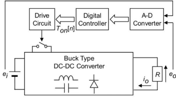
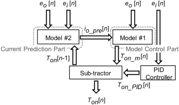
Figure 1 describes the digital control dc-dc converter. A main circuit is a buck type dc-dc converter. In this figure, ei is the input voltage, eo is the output voltage, R is the load resistor and io is the output current. ei and eo are detected and inputted to the digital control circuit. Then the on-time Ton[n] is determined by the digital control circuit. The output current was detected in the existing model control. Thus, the detecting resistor was needed. It is eliminated in the propose method because io is predicted. Figure 2 details the configuration of the digital control circuit. In this figure, ei and eo are inputted into the pre-amplifier. They are amplified by Aei and Aeo, respectively. Aei and Aeo are the gain of each pre-amplifier. The digital controller consists of the output current predictor (Model #1), the static model controller (Model #2) and the PID controller. ei[n-1] is sent to Model #1 and Model #2 and also eo[n-1] is sent to Model #1 and PID controller. Ton[n] is determined by those control parts.
Buck Type DC-DC Converter R io Drive Circuit Digital Controller A-D Converter eo Ton[n] ei
Fig. 2. Configuration of digital control circuit.
Fig. 3. Flowchart of sensorless model control.
A. MODEL CONTROL
In Model #1, the predicted output current io_pre[n] is calculated by using the digital value Ton[n-1] of on-time, ei[n-1] and eo[n-ei[n-1]. The equation for the prediction of output current is shown below [5]:
Ts D o Ts D i on CCM pre o rN V b n e N V a n e n T n i ) ] 1 [ ( ) ] 1 [ ]( [ ] [ _ _ (1) ) ] 1 [ ( 2 ] 1 [ ) ] 1 [ )( ] 1 [ ] 1 [ ( ] [ 2 _ _ D o s D i o i DCM pre o V b n e L n T T V a n e b n e a n e n i on (2)
In the transient state, the predicted current becomes oscillatory due to the fluctuation of the on-time. Therefore, the damping ratio is used to suppress the oscillation. Although it can bring
the stable operation of the sensorless model control, the predicted output current cannot trace the output current quickly. The bias value Ton_m[n] is calculated in Model #2 by using io_pre[n] and ei[n]. There are two equations for the calculation of Ton_m[n]. They are expressed as follows [5]:
Eo rio pre CCMn VD D V a n i e Ts N n CCM m on T _ _ [ ] ) ] [ ( ] [ _ _ (3)
s
T
o
E
a
n
i
e
D
V
a
n
i
e
D
V
o
E
n
DCM
pre
o
Li
2
Ts
N
n
DCM
m
on
T
)
*
]
[
)(
]
[
(
)
*
](
[
_
_
]
[
_
_
(4) In these equations, Ts is the switching period and NTs are the resolution of digital PWM generator. r and VD are internal lossand diode forward voltage. r is omitted in (2) because it does not almost affect on the calculation result of (4). Also,
a
andb
are given by
a
A
eiG
AD_ei (5)b
A
eoG
AD_eo (6) where GAD_ei and GAD_eo are the gains of the A-D converter for ei and eo. The index n denotes the sampling point obtained at the n-th switching period. Figure 3 shows the flowchart of the sensorless model control. Equations (1) and (2) are switched and applied depending on the operation modes of the dc-dc converter, which are the current continuous mode (CCM) and the current discontinuous mode (DCM). Equations (1) and (2) are calculated simultaneously and compared with each other. Larger values of them are applied as io_pre[n] and the operation mode of the dc-dc converter is judged. Ton_m[n] is calculated according to the operation mode. The model control can adjust the operating point correctly according to io, and therefore can regulate eo. B. TRANSIENT IMPROVEMENT FUNCTIONNext, the function Ton_tr[m] that changes the bias value rapidly is applied to realize the quick response. It is represented by m k k m tr on T _ [ ] 1 2 (7) k1 is the peak value of Ton_tr[m], k2 is the amount of decrement and m (m = 0, 1, 2,・・・) is the number of the switching (or control) period after the start of adjunction of Ton_tr[m]. When the output voltage exceeds the threshold value, this function is applied and the bias value is changed as
(1) (2) (1) ≧(2 ) io_pre[n]=(1) True False CCM DCM eo[n] ei[n] Ton[n-1] Ton_m[n] =(3) Ton_m[n] =(4) io_pre[n]=(2) Model #2 Model #1 io_pre[n] Model #2 Model #1 Sub-tractor PID Controller Ton_PID [n] Ton[n] Ton_m[n] eo [n]
Current Prediction Part
Ton[n-1]
Model Control Part
ei [n] eo [n] ei [n]
Fig. 4. Transient improvement function and its principle.
Fig. 5. On-time, Ton, of main switch generated by addition of calculation results, Ton_PID, Ton_model and Ton_tr.
shown in Fig. 4. Ton_tr[m] increase to k1 immediately, and then it decreases depending on k2. When Ton_tr[m] becomes zero or less, the adjunction is end. The improvement of the transient characteristics of the output voltage is obtained by suppressing the undershoot of output voltage when the transient state begins. The final on-time Ton[n] is shown as follows: ] [ _ ] [ _ ] [ _ ] [n Ton PIDn Ton m n Ton tr m on T (8)
In (8), Ton_PID[n], Ton_m[n] and Ton_tr[m] are the calculation results of the PID controller, the model controller and the transient improvement function, respectively. Therefore, Ton[n] is illustrated as in Fig. 5.
III. SIMULATION RESULT
In this section, the transient characteristics are considered in the load step from 0.05 A to 1 A. This means that the load
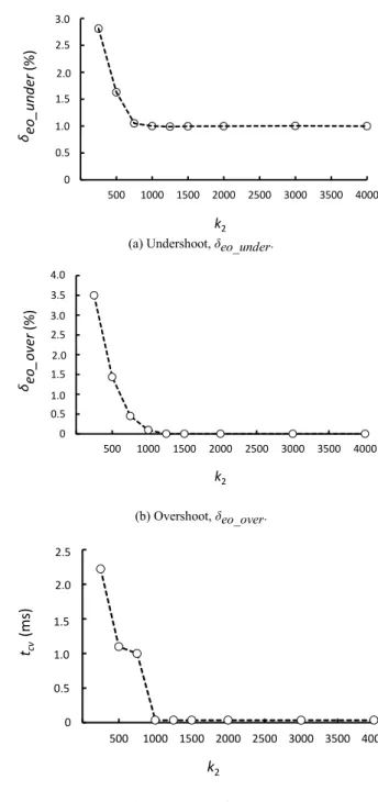
(a) Undershoot, δeo_under.
(b) Overshoot, δeo_over.
(c) Convergence time, tcv.
Fig. 6. Transient characteristics of output voltage, eo, under changing amount of decrement, k2, in case of load step from 0.05 A to 1 A.
change is assumed from no load to full load condition. The switching frequency fs is 100 kHz. Parameters of the circuit are as follows: ei = 20 V, the reference voltage of output voltage, Eo* = 5 V, L = 196 μH and C = 891 μF. The resolution of A-D converter is 11 bits and NTs is 2000. The transient characteristics of the proposed method under changing k2 are indicated in Fig. 6. Considering the upper limit value of the on-time, k1 is designed as 1230 because the
0 0.0005 0.001 0.0015 0.002 0.0025 0 500 1000 1500 2000 2500 3000 3500 4000 2.5 2.0 1.5 1.0 0.5 tcv (ms ) k2 0 0.5 1 1.5 2 2.5 3 3.5 4 0 500 1000 1500 2000 2500 3000 3500 4000 4.0 3.0 1.0 2.0 δeo_o ve r (%) k2 0 0.5 1 1.5 2 2.5 3 0 500 1000 1500 2000 2500 3000 3500 4000 3.0 2.0 1.0 δeo_under (%) k2 t
Existing sensorless model control
Proposed method k1 -k2 m ±0.5% Ton t eo
+
+
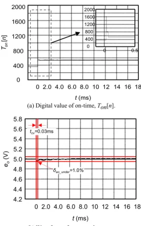
0 t Ton_m t 0 Ton_tr 0 t Ton_PID 0 t Ton(a) Digital value of on-time, Ton[n].
(b) Waveform of output voltage, eo.
Fig. 7. Transient response of proposed method when k1 and k2 are equal to 1230 and 250, respectively.
on-time is about 370 when io is 0.05 A. KP is 4, KD is 4 and KI is 0.004 in the proposed method. Therefore, 1250 is chosen as a proper value of k2. The waveforms in the transient state of the proposed method are depicted in Figs. 7 and 8 in two cases of k2 = 250 and 1250. The proposed method can increase Ton[n] immediately at the start of the transient state in both cases. From the enlarged view of Ton[n], it can be confirmed that the on-time varies according to the principle as shown in Fig. 5. Thus, the undershoot of the output voltage is suppressed as shown in Figs. 7 and 8. In Fig. 9, the results of existing sensorless model [5] are also shown. When k2 is set to 250, the overshoot δeo_over of eo is 3.5%. δeo_under is 2.9%. tcv is 2.2 ms as presented in Fig. 7. However, the improvement is not enough because k2 is not proper value in this situation. When k2 is set to 1250, a superior transient response is given. δeo_under is 1.0%. tcv is 0.03 ms as illustrated in Fig. 8. Compared with the existing sensorless model, δeo_under and tcv are improved by 83% and 99%, respectively. As a result, parameters of transient improvement function should be set to suppress the undershoot at the start of the transient state by increasing the on time of the main switch
(a) Digital value of on-time, Ton[n].
(b) Waveform of output voltage, eo.
Fig. 8. Transient response of proposed method when k1 and k2 are equal to 1230 and 1250, respectively.
(a) Digital value of on-time, Ton[n].
(b) Waveform of output voltage, eo.
Fig. 9. Transient response of existing sensorless model [5].
tcv=6.3ms δeo_under=6.0 % eo (V) 5.4 5.8 5.2 5.0 4.8 5.6 4.6 4.4 4.2 0 2.0 4.0 6.0 8.0 10 14 t (ms) 18 12 16 tcv=0.03ms δeo_under=1.0% eo (V) 5.4 5.8 5.2 5.0 4.8 5.6 4.6 4.4 4.2 0 2.0 4.0 6.0 8.0 10 14 t (ms) 18 12 16 0 2.0 4.0 6.0 8.0 10 14 t (ms) 18 12 16 2000 1600 1200 800 400 Ton [n ] 0 0 0.5 2000 1600 1200 800 400 0 tcv=2.2ms δeo_under=2.9% eo (V) 5.4 5.8 5.2 5.0 4.8 5.6 4.6 4.4 4.2 0 2.0 4.0 6.0 8.0 10 14 t (ms) 18 12 16 δeo_over=3.5% 0 2.0 4.0 6.0 8.0 10 14 t (ms) 18 12 16 Ton [n ] 2000 1600 1200 800 400 0 0 2.0 4.0 6.0 8.0 10 14 t (ms) 18 12 16 2000 1600 1200 800 400 Ton [n ] 0 0 0.5 2000 1600 1200 800 400 0 1351
momentarily. Therefore, in this case, the transient improvement function can improve the transient response even if the function is valid for only one switching period.
IV. CONCLUSION
In this paper, the function that improves the transient response of the output voltage is added to the sensorless model control at the beginning of the transient state. Also, its effectiveness is validated under changing its parameters. Consequently, the transient response of the output voltage is improved when those parameters are set to proper values judged from simulation results. Although it is applied for only one switching period, the transient improvement function can improve the transient response in this case. From the results, the proposed method is useful for applications of dc-dc converter that needs a wide load range.
REFERENCES
[1] L. Corradini, E. Orietti, P. Mattavelli and S. Saggini, “Digital hysteretic voltage-mode control for dc-dc converters based on asynchronous sampling,” IEEE Trans. Power Electronics, Vol. 24, No. 1, pp. 201-211, Jan. 2009.
[2] G. Feng, E. Meyer and Y. Liu, “A new digital control algorithm to achieve optimal dynamic performance in dc-to-dc converters,”
IEEE Trans. on Power Electronics, pp. 1489-1498, Jul. 2007.
[3] R. C. N. Pilawa-Podgurski, W. Li, I. Celanovic and D. J. Perreault, “Integrated cmos dc-dc converter with digital maximum power point tracking for a portable thermophotovoltaic power generator,” Proc. of IEEE Energy Conversion Congress and Exposition, pp. 197-204, Sep. 2011.
[4] K. De Cuyper, M. Osee, F. Robert and P. Mathys, “A digital plat form for real-time simulation of power converters with high switching,” in Proc. IEEE Power Electronics and applications, pp. 1-10, Sep. 2011.
[5] T. Ueno, T. Miyazaki, T, Ogawa and T. Itakura, “A 600 mA, constant on-time controlled DC-DC converter with 67% conversion efficiency at an output current of 23 μA,” in Proc. IEEE Applied Power Electronics Conference and Exposition, pp.1932-1935, Mar. 2014.
F. Kurokawa, T. Ishibashi, J. Sakemi and T. Babasaki, “An Auto-Tuning Digital Control for Buck-Boost DC-DC Converter,” Proc. of International Telecommunications Energy Conference, pp. 1-5, June. 2010.
[6] T. Babasaki, T. Ishibashi, J. Sakemi and F. Kurokawa, “Improved Auto-Tuning for Wide Input Voltage Range Digital Control Buck-Boost DC-DC Converter,” Proc. of Interntional Conference on Electrical Machines and Systems, pp. 40-43, Oct. 2010
[7] J. Liang and R. G. Harley, “Feed-forward transient compensation control for dfig wind generators during both balanced and unbalanced grid disturbances,” Proc. Of IEEE Energy Conversion Congress and Exposition, pp. 2389-2396, Sep. 2011.
[8] F. Kurokawa, J. Sakemi, A. Yamanishi and H. Osuga, “A new quick transient response digital control dc-dc converter with smart bias function,” Proc. of International Telecommunications Energy Conference, pp. 1-7, Oct. 2011.
[9] F. Kurokawa and S.Hirotaki, “Model control dc-dc converter without current detection,” in Proc. IEEE International Conference on Intelligent Green Building and Smart Grid, pp. 1-5, Apr. 2014. [10] F. Kurokawa and S. Hirotaki, “A novel sensorless model control
dc-dc converter,” in Proc. IEEE Renewable Energy Research and Application , pp 663 - 667, Oct. 2014.
[11] F. Kurokawa and S.Hirotaki, “A new high performance dc-dc converter with sensoress model reference modification” Proc. of International Telecommunications Energy Conference, pp. 1-5, Oct. sep. 2014.
[12] L. Jia, Z. Hu, Y. Liu and P. C. Sen, “A practical control strategy to improve unloading transient response performance for buck converters,” Proc. of IEEE Energy Conversion Congress and Exposition, pp. 397-404. Sep. 2011.
[13] P. Shangzhi; P. K. Jain, ”A low-complexity dual-voltage-loop digital control architecture with dynamically varying voltage and current references, ” IEEE Trans. Power Electronics, Vol. 29, No. 4, pp. 2049-2060, Apr. 2014.
[14] C. Wen, B. Fahimi, E. Cosoraba, Y. Fan, ” Stability analysis and voltage control method based on virtual resistor and proportional voltage feedback loop for cascaded dc-dc converters,” Proc. of Energy Conversion Congress and Exposition, pp. 3016-3022, Sep. 2014.