Digitally Proportional Gain Varying Method for
DC-DC Converter
Yudai Furukawa, Takuya Shirakawa and Fujio Kurokawa
Graduate School of EngineeringNagasaki University Nagasaki, Japan
Ilhami Colak
Faculty of Engineering and Architecture Gelisim University
Istanbul, Turkey [email protected] Abstract— The purpose of this paper is to propose a digitally
proportional gain varying method for dc-dc converter. In the proposed method, the proportional gain is set to a small value in the steady state and is changed to a large value over stability limit for only a short time in the transient state. Using the proposed method, the transient response can be improved while the dc-dc converter system is kept in stable. Compared with the conventional PID control, the undershoot and the convergence time are improved by 69% and 75%, respectively. Furthermore, the capacitance of output smoothing capacitor must be set to a large value to maintain the stability of system when the control gain is set to a very large value. However, that can be reduced because the very large gain is set for only a short time to improve the transient response in the proposed method. Therefore, the miniaturization of main circuit can be expected.
Keywords dc-dc converter; digital control; proportional gain I. INTRODUCTION
In recent years, the power consumption has increased by the rapid spread of the IT equipment. For this reason, the saving energy is important and the energy management is required as the function of power supplies. The digital control attracts attention because it is effective to realize such function [1], [2]. Also, the digital control has many advantages: the visualizing the power consumption, the robustness against the aging degradation, the communication with other external component and so forth, which are required as the function of power supplies. Furthermore, the digital control can realize the complex control algorithm and correspond flexibly [3]-[10]. Generally, when the control gain is larger, the transient state is improved. However, the system becomes unstable when this gain is too large. Even if the control gain is within the stable range, this gain should be set to small to suppress the oscillation based on the limit cycle of peculiar to digital control. The authors focus on the flexibility of digital control and then propose the gain switching method to improve the transient response.
This paper presents a digitally proportional gain varying method for dc-dc converter to the improvement of transient response. In the proposed method, the proportional gain is raised to a large value over the stability limit for only a short
time and exponentially reduced to the initial value. Moreover, the output smoothing capacitor is enlarged to maintain the stability of the system when the extremely large control gain is set. The proposed method can maintain the stability of system in the steady state because the control gain is small and changes the proportional gain to the large one temporarily to improve the transient response in the transient state.
II. OPERATION PRINCIPLE
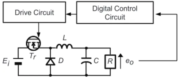
The block diagram of digital control buck type dc-dc converter is shown in Fig.1. Symbols represent circuit parameters as follows. Ei is an input voltage, and eo is an output voltage. Tr is a main switch, D is a flywheel diode, L is an energy storage reactor, C is an output smoothing capacitor and R is a load.
Figure 2 illustrates the scheme of digital controller. eo is sent to the pre-amplifier and fitted to the range of input voltage of A-D converter. The digital value eo[n] of eo is sent to the PID controller and the gain changer. The digital value of on time Ton[n] is sent to the PWM generator. The PWM generator generates the PWM signal, which is sent to the drive circuit.
Figure 3 describes the mechanism of gain changer. When
eo exceeds the threshold voltage Vth, the gain changer
suddenly switches the proportional coefficient KP_st for the steady state to the proportional coefficient KP_tr for the transient state to improve the undershoot and the overshoot. This gain changing is performed one times in the start of transient response as shown in Fig.3. KP_tr is set to a larger
Digital Control Circuit Drive Circuit Ei L D C R Tr eo
value than the stability limit of system. Based on the stability criterion of Hurwitz, the stability limit of KP is equal to about 28 in this system. Also, KP is attenuated according to following function. In (1), an exponential function is used to attenuate KP smoothly. t tr P st p K e K _ = _ −λ (1)
λ is an arbitrary constant that is derived as follows: ) ( _ _ _ _ P tr P st P tr T tr P e K t T K −λ = = (2) 5 . 0 1 _ = T × TP tr (3) tr P st P tr P T K K e _ _ _ = −λ (4) tr P st P tr P K K T _ _ _ =ln −
λ
(5) tr P st P tr P K K T _ _ _ ln 1 − =λ
(6)where T1 is the time from the start of the transient state to the bottom of the first undershoot in the conventional PID control.
TP_tr is the time when the gain changer works. TP_tr is set to
0.5 times of T1 not to affect excess range by large KP. KP is reduced from KP_tr to KP_st during TP_tr.
III. SIMULATED RESULTS
In this section, the transient responses of the conventional PID control and proposed gain switching method are discussed. The simulator is PSIM. The switching frequency fs is 100 kHz (Ts = 1/fs = 10 ȝs). As the main circuit parameters: Ei = 20 V,
Eo* = 5 V, C = 940 ȝF and L =189 ȝH. The forward voltage
drop VD of diode is 0.3 V. When the main switch is on, the internal resistance r1 of the dc-dc converter is 0.22 Ω. When the main switch is off, the internal resistance r2 of the dc-dc converter is 0.22 Ω. The load varies stepwise from 25 Ω to 5 Ω. The resolution of A-D converter is 12 bits. Vth is set to 20 mV in order to work the gain changer ideally. The evaluated items are the undershoot, the overshoot and the convergence time Tcv of eo. Tcv means the time when eo converges within
Fig. 3. Mechanism of gain changer.
eo Transient State KP_tr Vth KP_st TP_tr
Fig. 2. Scheme of digital controller. Pre-Amplifier A-D Converter PID Controller Gain Changer PWM Generator eo eo[n] Ton Ton[n] 0 20 40 60 80 5 4 3 2 1 Under shoot ( % ) KP_tr (a) Undershoot. O ver shoot ( % ) 0 20 40 60 80 5 4 3 2 1 KP_tr (b) Overshoot. 0 20 40 60 80 4 3 2 1 T
cv
(m s) KP_tr (c) Tcv.1% from the desired voltage.
The trend of transient characteristics, which is shown in Fig. 4 is evaluated with changing KP_tr. PID parameters are KP_st is 1, KI is 0.015, KD is 1. In this situation, the transient response is improved along with the increase of KP_tr.
Figure 5 depicts the transient response of conventional PID. The undershoot, the overshoot and Tcv are 4.8%, 2.9% and 3.6 ms, respectively. Also, T1 equals 480 ȝs. From (3) and (6), Ȝ equals 15861 when KP_tr is 45 and 17990 when KP_tr is 75. Figure 6 illustrates the transient response, the change of KP and the change of Ton[n] of proposed method when KP_tr is 45.
KP is suddenly varied to 45 and Ton[n] varies drastically. The
undershoot and Tcv are 1.5% and 0.9 ms, respectively. Compared with the conventional PID control, the undershoot and Tcv are improved by 69% and 75%, respectively. With respect to the overshoot, it is perfectly improved. Figure 7 shows the transient response, the change of KP and the change of Ton[n] of proposed method when KP_tr is 75. KP is suddenly varied to 75 and Ton[n] varies drastically. The undershoot, the overshoot and Tcv are 1.8%, 0.4% and 1.6ms, respectively. Compared with the conventional PID control, the undershoot, the overshoot and Tcv are improved by 63%, 86% and 52%, respectively. However, when KP_tr is set to 75, the transient response is worse compared with Fig. 6. Therefore,
KP_tr should be set properly. In this paper, the optimum KP_tr
is determined as 45. Figure 8 illustrates the transient response of conventional PID when KP_st is 45. The system becomes unstable and the output voltage does not converge after the load step because this KP_st is outside the stable range. Figure
9 shows the transient response of conventional PID when
KP_st is 4. The undershoot, the overshoot and Tcv are 3.2%,
1.5% and 1.6 ms, respectively. Compared with Fig. 5, the
Fig. 7. Transient response of proposed method when KP_tr is 75. 5.2 5.0 4.8 eo (V ) 5.4 4.6 Tcv: 1.6ms Undershoot: 1.8% Overshoot: 0.4% KP 40 20 0 60 80 KP_st=1 KP_tr=75 1000 1100 1200 1300 1400 1500 NTon 0 10 t(ms) 20 5 15 1600
Fig. 5. Transient response of conventional PID control. KP 40 20 0 60 80 KP_st=1 1000 1100 1200 1300 1400 1500 NTo n 0 10 t(ms) 20 5 15 1600 5.2 5.0 4.8 eo (V ) 5.4 4.6 Tcv: 3.6ms Undershoot: 4.8% Overshoot: 2.9%
Fig. 6. Transient response of proposed method when KP_tr is 45. KP 40 20 0 60 80 KP_st=1 KP_tr=45 1000 1100 1200 1300 1400 1500 NTon 0 10 t(ms) 20 5 15 1600 5.2 5.0 4.8 eo (V ) 5.4 4.6 Tcv: 0.9ms Undershoot: 1.5%
transient response is improved. In this condition, the oscillation based on the limit cycle occurs in steady state before the load step. From Figs. 8 and 9, KP_st should be set to a very small in the conventional PID control. Generally, the capacitance of output smoothing capacitor must be larger when KP_st is set to a large value because the system becomes unstable in the
steady state. On the other hand, in the proposed method, KP_st can be set to a very small because KP changes to very large in transient state. Therefore, the main circuit can be designed in small size by using the proposed method.
Next, TP_tr is considered. It is the period of change of proportional gain KP. In this section, TP_tr is represented by
Fig. 8. Transient response of conventional PID control when KP_st is 45. 0 10 t(ms) 20 5 15 5.2 5.0 4.8 eo (V ) 5.4 4.6
Fig. 9. Transient response of conventional PID control when KP_st is 4. 5.2 5.0 4.8 eo (V ) 5.4 4.6 Undershoot: 3.2% Overshoot: 1.5% Tcv: 1.6ms 0 10 t(ms) 20 5 15
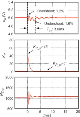
Fig. 10. Transient response of proposed method when Į is 0.3. KP 40 20 0 60 80 KP_st=1 KP_tr=45 500 1000 NTo n 0 10 t(ms) 20 5 15 2000 1500 5.2 5.0 4.8 eo (V ) 5.4 4.6 Tcv: 2.5ms Undershoot: 2.9% Overshoot: 1.1% 5.2 5.0 4.8 eo (V ) 5.4 4.6 Tcv: 3.0ms Undershoot: 1.6% Overshoot: 1.2% KP 40 20 0 60 80 KP_st=1 KP_tr=45 500 1000 NTo n 0 10 t(ms) 20 5 15 2000 1500
Fig. 11. Transient response of proposed method when Į is 5.
5.2 5.0 4.8 eo (V ) 5.4 4.6 Tcv: 1.3ms Undershoot: 1.2% Overshoot: 1.1% KP 40 20 0 60 80 KP_st=1 KP_tr=45 500 1000 NTo n 0 10 t(ms) 20 5 15 2000 1500
following equation.
α
× = 1 _ T TP tr (7)where TP_tr is set to Į times of T1. Figures 10, 11 and 12 illustrate the transient response, the change of KP and the change of Ton[n] of proposed method when Į is 0.3, 5 and 30. Also, KP_tr is 45. KP is suddenly varied to 45 and Ton[n] varies drastically. Consequently, the transient responses are improved compared with the conventional PID control in Fig. 5 when Į is set to 0.3, 0.5, 5 and 30. Meanwhile, when Į is too large, the waveform of the output voltage is vibrated. Moreover, the transient response is improved only a little when Į is too small. Therefore, Į should be set to 0.5 because the best of transient response in Į is obtained.
IV. CONCLUSION
This paper proposed a digitally proportional gain varying method for dc-dc converter. In the proposed method, the proportional gain is set to a small value in the steady state and a large value over the stability limit for only a short time in the transient state. The proportional gain change is realized independently of the stability of the system. As a result, the transient response can be improved by varying the proportional gain to a value over the stability limit temporarily in transient state. When KP_tr is equal to 45, the undershoot and Tcv are improved by 69% and 75%, respectively. With respect to the overshoot, it is perfectly improved. Although the capacitance of output smoothing capacitor must be larger when a large KP is set because the system becomes unstable in the steady state, the capacitance can be reduced and the main circuit can be designed in small size by using the proposed method. Also,
TP_tr should be set properly because the waveform of output
voltage is vibrated when TP_tr is too long.
REFERENCES
[1] D. Maksimovic, R. Zane and R. Erickson “Impact of digital control in power electronics," Proc. of IEEE International Symposium on Power Semiconductor Devices and ICs, pp. 13-22, May 2004.
[2] P. Zhao, S. Suryanarayanan and M. G. Simoes "An energy management system for building structures using a multi-agent decision-making control methodology," IEEE Trans. on Industry Applications, vol. 49, no. 1, pp. 322-330, Jan./Feb. 2013.
[3] C. Hung Tsai, C. Hung Yang, J. Hung Shiau and B. Ting Yeh, “Digitally controlled switching converter with automatic multimode switching,” IEEE Trans. on Power Electronics, vol. 29, no.4, pp. 1830-1839, Apr. 2014.
[4] A. Costabeber, P Mattavell, S. Saggini and A. Bianco“Digital autotuning of dc-dc converters based on a model reference impulse response," IEEE Trans. on Power Electronics, vol.26, no. 10, pp.2915-2924, Oct. 2011.
[5] R. Priewasser, M. Agostinelli, C. Unterrieder, S Marsili and M. Huemer "Modeling, control, and implementation of dc ̄ dc converters for variable frequency operation," IEEE Trans. on Power Electronics, vol.29, no.1, pp.287,301, Jan. 2014.
[6] A. Radic, A. Straka, A. Prodic, "Synchronized zero-crossing-based self-tuning capacitor time-constant estimator for low-power digitally controlled dc ̄ dc converters," IEEE Trans. on Power Electronics, vol.29, no.10, pp.5106,5110, Oct. 1 2014
[7] R. Silva-Ortigoza, V.M. Hernandez-Guzman, M. Antonio-Cruz and D. Munoz-Carrillo, "DC/DC buck power converter as a smooth starter for a dc motor based on a hierarchical control," IEEE Trans on Power Electronics, vol.30, no.2, pp.1076,1084, Feb. 2015.
[8] M. Algreer, M. Armstrong, and D. Giaouris, “Adaptive pd+i control of a switch-mode dc–dc power converter using a recursive fir predictor,” IEEE Trans. on Industry Applications, vol. 47, no.5, pp. 2135-2144, July 2011.
[9] V. Arikatla, and Jaber A. Qahouq, “DC-DC power converter with digital PID controller,” in Proc. IEEE Applied Power Electronics Conference and Exposition, pp. 327-330, Mar. 2011.
[10] S. Saggini, M. Loghi, O. Zambetti, A. Zafarana and L. Corradini, “Autotuning technique for digital constant on-time controllers,” in Proc. IEEE Applied Power Electronics Conference and Exposition, pp. 1059-1065, Mar. 2014.
![Fig. 2. Scheme of digital controller. Pre-AmplifierA-D ConverterPIDControllerGainChangerPWMGeneratoreoeo[n]TonTon[n] 0 20 40 60 8054321Undershoot (%)KP_tr(a) Undershoot](https://thumb-eu.123doks.com/thumbv2/9libnet/3580751.19920/2.892.510.768.462.1026/scheme-digital-controller-amplifiera-converterpidcontrollergainchangerpwmgeneratoreoeo-tonton-undershoot-undershoot.webp)