CAPACITY AND SPECTRUM EFFICIENCY
ANALYSIS OF AN ASYMMETRIC PMR
SYSTEM WITH DAB DOWNLINK
A THESIS
SUBMITTED TO THE DEPARTMENT OF ELECTRICAL AND
ELECTRONICS ENGINEERING
AND THE INSTITUTE OF ENGINEERING AND SCIENCE
OF BILKENT UNIVERSITY
IN PARTIAL FULFILLMENT OF THE REQUIREMENTS
FOR THE DEGREE OF
MASTER OF SCIENCE
By
Ersin Şengül
August, 2003
ii
I certify that I have read this thesis and that in my opinion it is fully adequate, in scope and in quality, as a thesis for the degree of Master of Science.
Prof. Dr. Y. Ziya Ider (supervisor)
I certify that I have read this thesis and that in my opinion it is fully adequate, in scope and in quality, as a thesis for the degree of Master of Science.
Prof. Dr. Hayrettin Köymen
I certify that I have read this thesis and that in my opinion it is fully adequate, in scope and in quality, as a thesis for the degree of Master of Science.
Asst. Prof. Dr. Nail Akar
Approved for the Institute of Engineering and Science
Prof. Dr. Mehmet Baray Director of the Institute
iii
ABSTRACT
CAPACITY AND SPECTRUM EFFICIENCY
ANALYSIS OF AN ASYMMETRIC PMR SYSTEM
WITH DAB DOWNLINK
Ersin Şengül
M.S. in Electrical and Electronics Engineering
Supervisor: Prof. Dr. Y. Ziya İder
August, 2003
Different trunked Private Mobile Radio (PMR) systems have been designed over the last several decades, all of which have symmetric downlink and uplink channel capacities. Due to this symmetry, those systems may not be spectrally efficient in case of different types of services which are only supported by PMR systems, such as group (acknowledged or unacknowledged) and broadcast calls, either voice or data. In this thesis, a new asymmetric trunked PMR system comprising an OFDM based broadband, wide-area downlink and a narrowband cellular uplink, is proposed to achieve a higher capacity and higher spectral efficiency than current digital trunked PMR systems have. This thesis concentrates on the system capacity analysis of the proposed system associated only with the downlink part for voice communications, as well as the spectrum efficiency comparison of the proposed system with the Terrestrial Trunked Radio (TETRA) system, which is accepted as the spectrally most efficient PMR system. In this study, we study the performance and capacity of the proposed system using Digital Audio Broadcasting (DAB) downlink. In particular, we study the capacity of such a system for voice calls using voice activity detection and statistical multiplexing. Moreover, we show that, the capacity of the system can significantly increase, if the incoming calls, which
iv
cannot find an available channel, are allowed to wait a certain amount of time before occupying a channel. The system is shown to have high trunking efficiency since all users are assumed to use the pool of channels available in the wideband downlink. Spectral efficiency of the proposed system and a standard TETRA system are compared using numerical case studies against different traffic loads, cell sizes and number of clusters. The optimum point, with respect to number of clusters, up to which the proposed system is more efficient, is determined. It is shown that for a realistic PMR scenario the proposed system is more efficient up to 5 clusters, i.e. 35 cells, and therefore it can be concluded that the proposed system can be used efficiently in realistic situations.
Keywords: private mobile radio (PMR), spectrum efficiency, digital audio
broadcasting (DAB), orthogonal frequency division multiplexing (OFDM), broadband downlink.
v
ÖZET
DAB UYDU-YER BAĞI OLAN
ASİMETRİK BİR PMR SİSTEMİNİN KAPASİTE
VE SPEKTRUM VERİMLİLİĞİ ANALİZİ
Ersin Şengül
Elektrik ve Elektronik Mühendisliği Bölümü Yüksek Lisans
Tez Yöneticisi: Prof. Dr. Y. Ziya İder
Ağustos, 2003
Son birkaç on yıl içerisinde değişik PMR (Private Mobile Radio) sistemleri dizayn edilmiştir ve bunların hepsi simetrik uydu-yer ve yer-uydu kanal kapasitesine sahiptir. Bu simetri yüzünden, yukarıda bahsedilen sistemler, grup (onaylanmış ya da onaylanmamış) ve yayın konuşmaları gibi sadece PMR sistemleri tarafından desteklenen değişik tipte servisler göz önüne alıdığında, spektrum bazında verimli olmayabilirler. Bu tezde, günümüzdeki dijital demetlenmiş PMR sistemlerinin sahip olduğu kapasite ve spektrum verimliliğinden daha iyi kapasite ve spektrum verimliliğine ulaşmak için, OFDM (Orthogonal Frequency Division Multiplexing)’e dayalı, geniş bantlı, geniş alan kaplamalı uydu-yer bağı ve dar bantlı yer-uydu bağından oluşan yeni bir asimetrik PMR sistemi önerilmiştir. Bu tez, önerilen sistemin spektrum verimliliği açısından en verimli sistem olduğu kabul edilen TETRA (Terrestrial Trunked Radio) sistemiyle spektrum verimliliği bazında karşılaştırılmasının dışında, önerilen sistemin sadece uydu-yer bağı konuşmaları açısından sistem kapasitesi analizi üzerine yoğunlaşmıştır. Bu çalışmada, uydu-yer bağı olarak DAB (Digital Audio Broadcasting) kullanılarak önerilen sistemin performans ve kapasitesini inceledik. Ayrıca, öyle bir sistemin kapasitesini, ses aktivite algılaması ve istatistiki çoğullama kullanılarak da inceledik. Üstelik, eğer hali
vi
hazırda kanal bulamayan konuşmaların kanal işgal etmeden önce belirli bir zaman beklemelerine izin verildiğinde, sistemin kapasitesinin önemli bir ölçüde arttığını gösterdik. Sistemin demetleme verimliliğinin yüksek olduğu gösterildi, zaten tüm kullanıcıların geniş bantlı uydu-yer bağında hali hazırda bulunan kanal havuzunu kullanabildiği varsayılmıştır. Önerilen sistemin ve standart TETRA sisteminin spektrum verimliliği, değişik trafik yükleri, hücre büyükleri ve topak sayısı bazında nümerik örnek çalışmalarıyla karşılaştırıl-mıştır. Önerilen sistemin, topak sayısına göre, daha verimli olduğu optimum nokta belirlendi. Gerçekçi bir PMR senaryosu için, önerilen sistem 5 topağa kadar, yani 35 hücreye kadar daha verimli olduğu gösterildi ve dolayısiyle sistemin gerçekçi ortamlarda verimli bir şekilde kullanabileceği sonucuna varılabilir.
Anahtar kelimeler: PMR, spektrum verimliliği, dijital ses yayını (DAB),
vii
Acknowledgement
I would like to express my gratitude to Prof. Dr. Y. Ziya İder and Prof. Dr. Hayrettin Köymen for their supervisions, suggestions and encouragement throughout the development of this thesis.
I am also indebted to Asst. Prof. Dr. Nail Akar accepting to read and review this thesis and for their suggestions, as well as my colleague Başak Can.
It is a great pleasure to express my special thanks to my family who brought me to this stage with their endless patience and dedication. Finally, I would like to thank to my fiancée, Ahu, for her unconditional love and interest she has shown during all the stages of this thesis; without her this thesis would not have been possible.
viii
ix
Contents
1 Introduction 1 2 Overview of Private Mobile Radio (PMR) 7
2.1 Introduction 7
2.2 The PMR User Profiles 8
2.3 PMR Service Requirements 9 2.4 Operational Scenarios 13 2.5 PMR Standards 16 2.5.1 Analogue PMR 17 2.5.2 Digital PMR Systems 18 2.6 TETRA System 22
3 Overview of Digital Audio Broadcasting (DAB) 25
3.1 Introduction 25
3.2 System Description and Features 26
3.2.1 Transmission Coding and Time Interleaving 28
3.2.2 Main Service Multiplex 29
x
3.2.4 Transmission Frame and Modes 31
3.3 Modulation with OFDM 32
3.3.1 OFDM Signaling and Orthogonality 34 3.3.2 OFDM in Digital Audio Broadcasting 36 3.3.3 Multicarrier Allocation in OFDM 37
4 Capacity Analysis of the Proposed System 39
4.1 Introduction 39
4.2 Analysis Methods 40
4.2.1 Markov model of the system and analytical solution 41
4.2.2 Solution by simulation 44
4.2.2.1 Finding Noc using ON-OFF level simulation 44 4.2.2.2 Finding Npop using call level simulation 45 4.2.2.3 Finding Npop using call level simulation with
queuing 46
4.3 Results 46
4.3.1 Number of Ongoing Calls, Noc 47
4.3.2 Number of Users Supported by the System, Npop 48
4.3.3 Npop with Queuing 48
4.4 Discussion 52
5 Spectrum Efficiency of the Proposed System 54
xi
5.2 The TETRA System 58
5.3 The Proposed Asymmetric PMR System (TETRA-DAB System) 59 5.4 Comparative Results for the Spectrum Requirements of the
Proposed TETRA-DAB and TETRA Systems 60
5.4.1 Basic definitions and assumptions 60 5.4.1.1 Spectrum requirement of the TETRA-
DAB system 61
5.4.1.2 Spectrum requirement of the TETRA system 62
5.4.1.3 Cluster Size 64
5.4.2 Numerical Results 64
5.4.2.1 Single Cluster Case (7 cells) using the
Whole Capacity of DAB Downlink 66
5.4.2.2 Two Cluster Case (14 cells) using the
Whole Capacity of DAB Downlink 67
5.4.2.3 Multiple Cluster Cases using Different
Capacities of DAB Downlink 68
5.5 Discussion 75
6 Conclusions and Future Work 78
APPENDICES
A The relation between A_inddj and A_induin a cell 83
xii
List of Figures
2.1 Breakdown of PMR user community in the UK 9 2.2 Direct mode PMR configuration where communication takes
place without any base station or repeater 13 2.3 Dispatch mode PMR configuration where communication
takes place via a base station 14
2.4 Talkthrough repeater operation 14
2.5 Vehicle mounted repeater to increase the local
hand-held coverage 15
2.6 Cellular PMR configuration that is used in large PMR and
PAMR systems to increase the total capacity 16 2.7 Comparison of analogue and digital speech quality with
same noise threshold levels 19
3.1 (a) A conceptual DAB signal generator, (b) A conceptual
DAB receiver structure 27
3.2 Symbols with a guard interval 30
xiii
3.4 Concept of OFDM signal: (a) conventional multicarrier
technique (b) orthogonal multicarrier modulation technique 33 4.1 Markov model of the ON-OFF level characterization 42 4.2 Markov model of the call level characterization 43 4.3 Frame loss rate as a function of number of ongoing calls 48 4.4 GOS: Grade of service providing on the average 10-4 FLR
for GSM scenario. For GOS of % 2, optimum Npop is found
to be 4865. 49
4.5 GOS: Grade of service providing on the average 10-4 FLR for PMR scenario. Simulation results are very close to analytical
results. For GOS of % 2, optimum Npop is found to be 8765 50
4.6 GOS as a function of maximum waiting time for GSM scenario 50
4.7 GOS as a function of maximum waiting time for PMR scenario 51 4.8 The maximum number of users that can be supported by the
system as a function of maximum waiting time for GSM
scenario for 2% GOS and 10-4 frame loss rate 51 4.9 The maximum number of users that can be supported by the
system as a function of maximum waiting time for PMR
scenario for 2% GOS and 10-4 frame loss rate 52 5.1 Ratio of the total spectrum requirement of TETRA-DAB to
conventional TETRA system versus total traffic capacity of
DAB system for 1-cluster case 72 5.2 Ratio of the total spectrum requirement of TETRA-DAB to
xiv
DAB system for 3-cluster case 72 5.3 Ratio of the total spectrum requirement of TETRA-DAB to
conventional TETRA system versus total traffic capacity of
DAB system for 5-cluster case 73 5.4 Ratio of the total spectrum requirement of TETRA-DAB to
conventional TETRA system versus total traffic capacity of
DAB system for 6-cluster case 73 5.5 Ratio of the total spectrum requirement of TETRA-DAB to
conventional TETRA system versus total traffic capacity of
DAB system for 10-cluster case 74 5.6 Ratio of the total spectrum requirement of TETRA-DAB to
conventional TETRA system versus total traffic capacity of
DAB system for 15-cluster case 74 5.7 Ratio of the total spectrum requirement of TETRA-DAB to
conventional TETRA system versus the number clusters in
xv
List of Tables
2.1 Main parameters for TETRA system operation 22 3.1 The four different transmission modes of the DAB system 32 3.2 OFDM parameters for different transmission modes of
DAB system 37
4.1 System parameters for GSM and PMR [5] scenarios 47 5.1 Spectrum requirements for the TETRA-DAB system with
different cluster cases and traffic 69
5.2 Spectrum requirements for the TETRA system with different
1
Chapter 1
Introduction
Professional or Private Mobile Radio (PMR) systems are operated by a wide range of users, such as the Police and Fire Services, the utility (Gas, Water and Electricity) and transportation companies, and for on-site applications such as in factories and airports [1]. Several PMR system standards have been developed and adopted in Europe, North America and Japan. Seven well known digital trunked PMR systems are Terrestrial Trunked Radio System (TETRA), Association of Public-Safety Communications Officials (APCO-25), Integrated Dispatch Radio System (IDRA), Digital Integrated Mobile Radio System (DIMRS), TETRAPOL system, Enhanced Digital Access Communications System (EDACS), and GEOTEK-FHMA system. Out of these PMR systems, APCO25, TETRAPOL and EDACS are based on FDMA technology; TETRA, IDRA and DIMRS are based on TDMA; and GEOTEK-FHMA is based on frequency hopping. All of these systems have a cellular architecture and they can use the allocated spectrum as efficiently as possible by making use of frequency reuse. They also have symmetric downlink and uplink channel capacities, having disadvantages in terms of spectral usage in some PMR applications, such as group calls. To
CHAPTER 1. INTRODUCTION
2
illustrate, in APCO25 both uplink and downlink channels have a bandwidth of 12.5 KHz. In TETRA, each channel is one fourth of a 25 KHz TDMA channel. One can refer to [2]-[4] for the details of the current PMR systems.
Although the present systems have been developed using different technologies, and for either general or more specific applications, they share a number of common features and objectives. Some of the common features of PMR systems, which also make them fundamentally different from Public Access Communications Systems (PACS), and which are especially important with respect to spectral efficiency considerations are:
• Typical lengths of calls are very short compared to the public telephone calls in a PACS and they serve a smaller population. Therefore PMR systems have considerably lower traffic per user.
• There are a number of voice and data applications, which are not supported by a PACS such as GSM. Most important of these are broadcast calls and group calls (acknowledged and unacknowledged) for both voice and data communications.
In this thesis, we propose a new PMR system, which has better spectral efficiency especially regarding broadcast and group calls. Spectrum efficiency is highly dependent on the channel assignment schemes and the proportion of different types of calls, since all call types have different channel allocation schemes. When a point-to-point individual call is initiated in a digital trunked PMR system, channel allocations are very similar to those in PACS. When a broadcast call is initiated, a downlink channel must be allocated in all cells in that PMR network. Similarly, when a group call is initiated, either data or voice, at least a downlink channel is allocated in all cells in which there exists a group member. If group members are distributed in more than one cell, spectral
CHAPTER 1. INTRODUCTION
3
efficiency decreases. However, if an asymmetric system as proposed in this study, where the downlink has wide area coverage, i.e. it covers the whole service area, is used, spectrum efficiency of the system is maintained even with group and broadcast calls, because for each broadcast or group call a single channel in the downlink is allocated. In PMR systems, group calls and broadcast calls constitute about 50% of all calls [5]. Therefore an asymmetric system as described above should provide significant increase in spectral efficiency.
Cellular PMR systems can increase their spectral efficiency by making use of frequency reuse. However for reasons as explained above regarding the channel requirements of broadcast calls and group calls, wide area coverage for the downlink part offers opportunity for additional spectrum efficiency. On top of this, a wide area downlink provides trunking efficiency. However this architecture, i.e. cellular uplink and single cell downlink, may not be efficient if the number of cells in the system is increased and more frequency reuse is employed, because in such a system there is no provision for frequency reuse in the downlink part. In this thesis we are aiming at determining the optimum point up to which the proposed system is more efficient than conventional digital PMR systems. We have particularly investigated this problem in reference to realistic PMR systems, which have significantly lower traffic, compared to a PACS.
A new digital trunked PMR system comprising an Orthogonal Frequency Division Multiplexing (OFDM) based broadband, wide-area downlink and a narrowband cellular uplink, is proposed in this study to achieve a higher spectral efficiency than the TETRA system, which is accepted to be the most efficient system among digital trunked PMR systems in terms of spectral usage. OFDM is a spectrally efficient multi-carrier digital modulation scheme, offering reliable reception under hostile reception conditions such as multipath
CHAPTER 1. INTRODUCTION
4
propagation [6], [7]. In addition, OFDM allows for intentional multipath, where all the transmitters within a Single Frequency Network (SFN) operate at the same frequency, thereby achieving wide area coverage. These multipaths are constructive within the Guard Interval, strengthening the signal level [6], [7]. As the OFDM downlink, we have considered in this study the use of a Digital Audio Broadcasting (DAB) system, which has well-established standards in terms of frequency allocations and protocols and reasonable cost [8].
This thesis concentrates on the system capacity analysis of the proposed system associated only with the downlink part for voice communications, as well as the spectrum efficiency comparison of the proposed system with the TETRA system [41],[42]. In the capacity analysis part, the number of subscribers that can be supported by the proposed system is calculated under several constraints such as grade of service (GOS) and bit error rate. In fact, this analysis can be seen as downlink capacity analysis because all capacity calculations are independent of the uplink part of the proposed system. The uplink part will certainly have a cellular architecture and have a capacity much larger than the downlink part by making use of frequency reuse. Therefore the system capacity is upper bounded by the downlink part and the downlink capacity can be seen as the system capacity of the overall proposed system. In particular, we study the efficiency of such a system for voice that would be obtained using silence detection. Moreover, we show that, if the incoming calls are allowed to wait a certain amount of deterministic time before occupying a channel, capacity can significantly increase.
For the spectrum efficiency analysis part, both the proposed system and the standard TETRA system are compared to demonstrate the advantages of the proposed system. In order to compare the spectral efficiencies of these PMR systems, a metropolitan area is assumed to be covered by either one of
CHAPTER 1. INTRODUCTION
5
the systems considering equal traffic patterns. Spectrum requirements in order to achieve the same Quality of Service (QoS), e.g. the same call delay probability, are calculated. In spectrum efficiency calculations, only individual and group calls are considered
Recently, there has been an increasing interest for high bit rate multimedia applications for mobile users, in the general framework of the convergence of cellular and broadcast networks [9], [10]. An asymmetric system with a wideband downlink for higher data rates is desirable, because it is generally accepted that wideband is needed more for downlink. Studies for such asymmetric systems have been undertaken in several projects in which the public access communications system, GSM, is complemented with DAB [11] or Digital Video Broadcasting (DVB) [12]. These proposals consider the broadband downlink only for multimedia applications, and voice calls are still carried by the narrowband channels. However if a broadband downlink is available then it may be possible to achieve spectrum efficiency for speech signals as well, if they are carried by the broadband downlink channel via a suitable trunking protocol. Asymmetric PMR systems have not yet been proposed.
The outline of this thesis is as follows. Chapter 2 contains an overview of PMR environment, including PMR user communities, service requirements such as reliability, fast call setup, speech and data transmission capability, group and broadcast calls, centralized and decentralized operation etc., some PMR configurations, which are used in realistic situations and finally the analogue and digital PMR standards. In Chapter 3, a brief overview of the DAB system is presented, including basic system description and features as well as the basic properties of the modulation with OFDM. Chapter 4 covers the details of the capacity analysis of the proposed system. Both analytical models and simulation algorithms as well as the numerical results are presented
CHAPTER 1. INTRODUCTION
6
and discussed. In Chapter 5, the analysis made for the spectrum efficiency comparison of the proposed system with the standard TETRA system is described and discussed. Chapter 6 concludes this thesis and briefly describes future work.
7
Chapter 2
Overview of Private Mobile Radio
(PMR)
2.1 Introduction
Private (or professional) mobile radio (PMR) systems are systems set up by a company or group of users to provide mobile radio services for that group of users alone. By this way PMR systems differ from public access communication systems.
‘Walkie-talkie’ systems were the simplest form of PMR in which mobile stations communicate each other directly and there is no need for repeaters, base stations or a controlling network. While such systems are simple to set up and cheap to run, they are not very flexible since mobiles have to be within range of each other and calls to other networks is not possible. Later, a new service called PMR446 [13] in which eight 12.5 kHz channels were harmonized across Europe at 446 MHz in the PMR band was set up and replaced walkie-talkie systems.
CHAPTER 2. OVERVIEW OF PRIVATE MOBILE RADIO
8
At the other end of the PMR spectrum, several systems rival or even exceed the complexity of public communication systems. Companies or users may group together and use joint systems that are also called public access mobile radio (PAMR). PAMR systems are shared by several different user groups. PAMR or PMR systems with common protocols and interworking plan have the advantage of enabling users from different systems communicate each other directly. While such interworking can be done by routing calls through a fixed network, this adds delays which should be as little as possible in the PMR field. These interworking constraints have caused a movement towards open standards in the PMR environment.
An important question facing PMR users is which options will provide them with the most efficient service in terms of cost and spectrum. Conventionally, potential users were encouraged to use PMR systems for reasons such as to guarantee sufficient coverage, reasonable cost and to provide
supplementary services.
2.2 The PMR User Profiles
There is a wide range of users of PMR systems. The major sectors that are using PMR systems can be summarized as [1]:
• Public safety: Emergency services such as ambulance, police, fire, etc.
• National government: Governmental agencies such as customs,
non-emergency health.
• Local government
• Transport: Railways, airports, buses, taxis etc.
• Other utilities: Electricity, gas, water, coal.
• On site-PMR: General-purpose businesses operating in local areas or
CHAPTER 2. OVERVIEW OF PRIVATE MOBILE RADIO
9
• Other PMR: Operating over larger areas
• PAMR: PMR systems that are jointly used by different users or
companies.
A good example of a mature market for PMR is provided by the UK, having the second largest number of PMR users throughout the Europe. The breakdown of the UK PMR market is shown in Fig 2.1.
On-site 20% PAMR 11% Emergency services 11% Utilities 5% Transport 22% Local government 10% National government 2% Other PMR 19%
Figure 2.1: Breakdown of PMR user community in the UK [1].
PAMR operators provide many users with many different requirements. Consequently, they want to set up rich systems in terms of features. Furthermore, their interest is to use a spectrally efficient system, since capacity constraints will limit the number of customers.
2.3 PMR Service Requirements
There are several requirements of a private mobile radio system, most important of which provide users with the ability to communicate with each
CHAPTER 2. OVERVIEW OF PRIVATE MOBILE RADIO
10
other reliably. To be more specific, it is possible to point out several key requirements of PMR users. In no particular order, these requirements are [1]:
• Reliability. In the PMR market, many services are used in safety important
systems. The user involving in the operation of the service has the advantage of ensuring reliability and being independent from other PMR or PAMR operators. The lack of public access cellular communications systems to ensure quality of service (QoS) or grade of service (GoS) in all circumstances, may force customers to use a PMR system. A survey found that service availability was classed as “extremely important” by two-thirds of those questioned [14].
• Speech and data transmission capability. In addition to speech services,
mobile data services are increasingly used for information updating services, telemetry, or tracking. To illustrate, some companies are conducting trials on systems in which one can transmit medical telemetry, including still images, video, text messages and GPS data to support safety operations. As more data services develop, the applications that make use of them will also develop. Consequently, a flexible data service provision is critically crucial. In the survey, about 80% of users classed data communications as “important” [14].
• Point-to-point, group calls and broadcast calls. When a PMR system is
used, a flexible group call structure should be maintained where users share any information directly rather than having to relay it via others. As a result, in addition to the point-to-point (single terminal to single terminal) calls, group calls, calls involving a number of predefined users, and broadcast calls, where the calls involves all terminals in the network, are required.
• Centralized and decentralized operation. In many business sectors, a PMR
CHAPTER 2. OVERVIEW OF PRIVATE MOBILE RADIO
11
required. However, in some circumstances, it may also be important that users are able to communicate each other in the absence of a dispatcher or even any infrastructure at all. The survey [14] shows that about 80% of users classed direct mode operation as “important”, with over half of these saying that it was “very important”.
• Fast call set-up. Almost all PMR systems have a pressel or “push-to-talk”
button to activate any call to the user group or dispatcher without an answering procedure, rather than dialing a number to set up a call with called party answering a phone. Users look forward to being connected to the desired terminal(s) without delay since calls usually consist of a sentence or two. This situation is extremely important in the emergency services where the system may be used to give urgent commands. Therefore, dropping several words of the message due to call set up delay may have serious results.
• Good coverage. PMR users usually have less choice as to where to make a
call compared to a public cellular user. The area where the user is undertaking the work often limits the available locations. On the other hand, a mountain rescue service may require coverage in areas where public cellular systems are not needed. Sometimes, as well as overall area coverage, lack of blackspots within the covered area is also very essential.
• Long battery life. In the PMR environment, users maintenance costs some
price in terms of lost work time, and reliability of service is also very important. This compares with public cellular systems where users are responsible for battery charging.
• Flexibility. Flexibility with regard to services has already been covered, but
CHAPTER 2. OVERVIEW OF PRIVATE MOBILE RADIO
12
developing needs of the operators and users. In particular, the system should be scalable, so that the growth can be supported and adaptable to allow new services, which were not foreseen at the time of system installation.
• Low cost. Companies using PMR systems will consider costs over the entire
life of the equipment, including the capital costs for the infrastructure and maintenance costs. About 95% of the users classify cost as “important” [14].
There are also some other requirements which may not be necessary in all circumstances but will be needed by a large number of companies or users. These are security, call priorities, communication between networks, ease of licensing, and in-house control of system. Many PMR users expect high levels of security, with different forms, in terms of reliability of operation and protection of transmitted information from tampering and interception. Call priorities may be important for example in emergency services, where an emergency call should be able to pre-empt any other calls in order to access the network. In many circumstances, communications with general phone or data networks is a useful feature.
One requirement not mentioned above is efficient use of radio resources. In fact, capacity is normally not an issue to PMR users due to the length of the call and since licenses are relatively cheap in most countries. PMR users are concerned at a more general level as channels become scarce and have to be reused more frequently in high traffic areas such as cities. Division of available spectrum between different PMR users is of general concern since it means little trunking efficiency. As a result, there will be fewer channels than required in most large urban areas. The standardization authorities are likely to insist on spectrally efficient PMR systems with a narrow carrier spacing.
CHAPTER 2. OVERVIEW OF PRIVATE MOBILE RADIO
13
2.4 Operational Scenarios
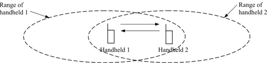
There are some PMR configurations [1] which are used in realistic scenarios and which enable us to understand basic operation types of the PMR systems. The simplest PMR configuration is point-to-point direct terminal communication. As seen from Fig.2.2, there is no need for an infrastructure, and in most cases, all terminals are within range of each other. Either single frequency is used or different frequencies can be used for different call groups.
Figure 2.2: Direct mode PMR configuration where communication takes place without any base station or repeater.
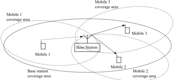
One of the most common PMR configurations is dispatch operation. At least two channels are used, one for uplink communications from mobile stations and one for downlink to the mobile stations. Messages from the dispatcher on the downlink can be received by all stations although individual addressing is possible. Fig.2.3 shows the dispatch operation where mobile-to-mobile communication is possible via the dispatcher and links with the public switched telephone or data networks are possible, again via the dispatcher.
If extended coverage is provided and central dispatcher or PSTN network is not necessary, base station can be used as repeater. This effectively
Handheld 1 Handheld 2
Range of handheld 1
Range of handheld 2
CHAPTER 2. OVERVIEW OF PRIVATE MOBILE RADIO
14
increases range of mobile stations as seen from Fig.2.4. If there were no repeater, mobile 1 would not be able to communicate with mobile 2 and 3.
Figure 2.3: Dispatch mode PMR configuration where communication takes place via a base station.
Figure 2.4: Talkthrough repeater operation.
A better option, although it requires more complexity, is trunked operation. In such a case, a number of channels are available and pooled between different PMR operators. This provides trunking efficiency and increases the probability of finding a free channel.
Base Station Dispatcher PSTN/PSDN Base Station Mobile 1 Mobile 2 Mobile 3 Base station coverage area Mobile 1 coverage area Mobile 3 coverage area Mobile 2 coverage area
CHAPTER 2. OVERVIEW OF PRIVATE MOBILE RADIO
15
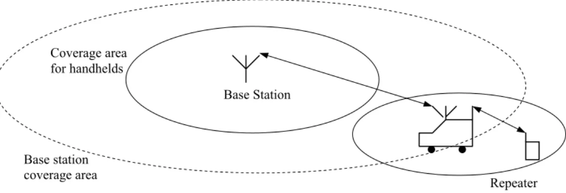
In many circumstances, a single base station will not be able to cover the entire service area. Remote radio ports with smaller powers can be used to cover blackspots. Hand-held terminals usually have lower power than mobile terminals mounted in vehicles especially due to battery and safety conditions, and therefore mobiles can receive signals at greater ranges than handheld terminals. Portable vehicle mounted repeaters can therefore be used to provide handheld coverage to users working near to their vehicles. In Fig.2.5, this mode of operation is shown and commonly used by emergency services.
Figure 2.5: Vehicle mounted repeater to increase the local hand-held coverage. If the service area to be covered is large, several base stations have to be used. If only a relatively low capacity is required, all these base stations can transmit the same signal in a system which known as “simulcasting”. In such a case system behaves in the same way as one large cell. In analogue systems the frequencies used in the different cells vary by a few hertz which reduces problems in overlap regions that receive signals from two or more cells. In a digital system this is more complex and systems must be carefully designed to ensure that terminals can receive an adequate signal in the overlap regions. [15] demonstrates that TETRA, which is digital trunked system, can support simulcast up to a point.
Base Station Coverage area
for handhelds
Base station
coverage area Repeater
CHAPTER 2. OVERVIEW OF PRIVATE MOBILE RADIO
16
Systems that have to support large capacities require the use of cellular schemes. Such systems have considerably more complex infrastructures than other configurations, supporting switching between base stations and handover of mobiles between different cells. Large PMR and PAMR operators need to use cellular configurations, which are shown in Fig. 2.6, to give them the required capacity. However, even large PMR and PAMR systems do not have as much traffic as public cellular systems have, and have a relatively flat architecture compared to the complex hierarchical network architecture of GSM [1].
Figure 2.6: Cellular PMR configuration that is used in large PMR and PAMR systems to increase the total capacity.
2.5 PMR Standards
With the move towards digital PMR systems, there has been a trend away from proprietary systems toward a public standard to which equipment must
BS BS BS BS BS BS BS BS PSTN/ PSDN Switching and control PSTN/ PSDN Switching and control Control station with dispatcher
CHAPTER 2. OVERVIEW OF PRIVATE MOBILE RADIO
17
conform, therefore allowing equipment from different manufacturers to be used together. Moves towards public standards have come from manufacturers and operators, as in the case of TETRA, or the user community, as in the case of APCO25.
Public standards have a number of advantages, as shown by the success of GSM in the digital mobile radio environment. Public standards enlarge the market, allowing an economy of scale as well as opening the market for more specialized areas. All the various standards include defined interface points allowing users to use different parts of the system from different suppliers. As well as forcing more competition between providers, it means that suppliers are no longer required to produce all the components of the system. Public standards also give users more freedom to move equipment between networks. This is less of an advantage than it would be in the case of public cellular systems, where some users want a high degree of mobility and roaming between networks. However, it can still be seen to be an advantage to many PMR users, especially those, such as the emergency services, who co-ordinate each other.
2.5.1 Analogue PMR
Early PMR systems were analogue and proprietary. However, a wish to share infrastructure costs and spectrum led to the development of trunked radio systems, with this development came the need for standards so that equipment could be sourced from different suppliers. The earliest such system, which is still available from a number different suppliers, is LTR (Logic Trunked Radio). A number of these systems are still in operation worldwide.
CHAPTER 2. OVERVIEW OF PRIVATE MOBILE RADIO
18
Another major analogue PMR standard is MPT1327 (Ministry of Post and Telecommunications), which was developed in the UK in the late 1980s, but has been adopted by manufacturers and implemented worldwide [1]. Although MPT1327 is more complex and expensive than simpler analogue systems, it is relatively efficient in terms of spectrum usage and offers some capabilities as well as the conventional PMR voice features such as group calls, fast call set-up and priorities. Manufacturers of LTR and MPT1327 equipment are still promoting their analogue systems, in particular for use in countries or areas without capacity constraints.
2.5.2 Digital PMR Systems
In late 1980s, success of wireless communications systems, particularly public access cellular systems, pointed out the need for new types of PMR systems. As PMR systems provide the required services to more customers, the systems have to expand their capacity to accommodate them. There exist two main reasons for the move towards new digital trunked PMR systems, one of which is to provide less costly ways to expand the system and the other is to be capable of supporting many new services.
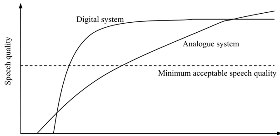
Digital systems, the systems in which the modulation scheme is digital, offer a large number of benefits over conventional analogue systems. A major advantage is the ability to receive the signal completely as long as the noise level is below a particular threshold value. There is also a disadvantage that when the noise level reaches the threshold of a digital system, the system performance falls off very rapidly, while the quality falls off steadily in an analogue system, as seen in Fig 2.7 [1].
CHAPTER 2. OVERVIEW OF PRIVATE MOBILE RADIO
19
Figure 2.7: Comparison of analogue and digital speech quality with same noise threshold levels.
The basic advantages of digital PMR systems over analogue systems can be summarized as [4]:
• A significant increase in system capacity.
• New services (e.g. data messaging, video services, priority access)
• Improved quality of service
• Added security and voice privacy
• Economic benefits.
Another advantage related to transmission of data, which can be sent directly in a digital system without the need for a modem and for trunking, as a digital signal can be manipulated more easily than a conventional one. Although digital modulation schemes are more complex than analogue modulation schemes, transmission of a speech signal as a digital signal allows for the use of efficient compression algorithms so that the spectral bandwidth needed for a speech signal is lower with digital modulation schemes.
Spee ch quality
Channel signal to noise level (SNR) Digital system
Analogue system
CHAPTER 2. OVERVIEW OF PRIVATE MOBILE RADIO
20
Digital PMR systems are more complex and therefore more expensive. On the other hand, the increased capacity and flexibility, availability of new services, increased spectrum efficiency and quality of service move PMR market to the digital systems as in the case of public access communication systems.
A number of digital trunked mobile radio systems have recently been developed in Europe and North America, Although these systems have been developed for either general-purpose applications or more specific users, they share a number of common features and objectives. There are seven well known Professional or Private Mobile Radio systems; Enhanced Digital Access Communications System (EDACS), GEOTEK-FHMA system, Integrated Dispatch Radio System (IDRA), Digital Integrated Mobile Radio System (DIMRS), TETRAPOL system, Association of Public-Safety Communications Officials (APCO25) and Terrestrial Trunked Radio System (TETRA) [3], [4].
EDACS is a proprietary trunked radio system from Ericsson, featuring distributed processing for enhanced reliability. First systems were installed in late 1980s, finding applications in the military field. When the system is introduced, a major selling point was its data services, which were not used in the PMR systems of that time. The system operates at 9600 baud for 25 kHz channel and 4800 baud for 12.5 kHz channels [4]. Although it was frequency division based, the system evolved to a three-time-slot TDMA system by 1994.
Geotek-FHMA is a digital system, which uses slow frequency hopping as well as FDMA scheme. The technology introduced is novel for the civil mobile radio users, being more common in secure military communications. The primitive incentive for developing FHMA has been spectral efficiency and FHMA systems are primarily focused on the PAMR market.
CHAPTER 2. OVERVIEW OF PRIVATE MOBILE RADIO
21
IDRA system and its standards were developed by the Association of Radio Industries and Businesses in Japan. The technical requirements of the specification aim at satisfying the needs of the users over a wide range of profession, from emergency services to industrial organizations. It has a TDMA based structure and 64 kbit/s transmission rate per RF carrier allocating a bandwidth of 25 kHz.
DIMRS is one of the methods being used especially in North America to provide integrated dispatch services and increase spectrum efficiency. It has a TDMA based structure and 64 kbit/s transmission rate per RF carrier allocating a bandwidth of 25 kHz.
TETRAPOL is a digital FDMA based PMR system. TETRAPOL offers a solution to the PMR environment at lower costs than systems like TETRA, albeit with slightly lower spectral efficiency and a more limited range of services, by combining digital modulation with FDMA technology. The TETRAPOL system uses a 64 kbit/s transmission rate per RF carrier allocating a bandwidth of 12.5 kHz.
APCO25 standard is a combination of conventional and trunked digital PMR technology. APCO25 compliant systems are primarily used for public safety applications. Furthermore APCO25 compliant stations can operate as conventional radios with or without the use of repeaters or as digital trunked radios. There are three basic communication channel types supported by the APCO system; 12.5 kHz digital, 6.25 kHz digital and 12.5 kHz analog for backwards compatibility. APCO system is an FDMA system and all radio channels can be set up as conventional and trunked radio channels. When set up as conventional, the same radio channel is used for both call setup and voice communications. When used as a trunked system, one of the radio channels in a base station is dedicated as a control channel.
CHAPTER 2. OVERVIEW OF PRIVATE MOBILE RADIO
22
2.6 The TETRA System
Terrestrial Trunked Radio System (TETRA) [1],[16] has been developed to allow migration from analogue PMR systems and therefore radio parameters have been adapted. The key air interface parameters are shown in Table 2.1, which indicates that the specific technology adopted for the TETRA system, and are driven by the requirements of PMR environment. As shown Table 2.1, the carrier spacing is 25 kHz, which allows direct replacement of two conventional 12.5 kHz analogue FM channels or a single conventional 25 kHz analogue FM channel.
Table 2.1: Main parameters for TETRA system operation Parameter Value
Carrier Spacing 25 kHz Modulation π/4-QPSK Carrier data rate 36 kbit/s
Vocoder data rate ACELP (4.56 kbit/s net, 7.2 kbit/s gross ) Access method TDMA with 4 time slots/carrier
User data rate 7.2 kbit/s per time slot Maximum data rate 28.8 kbit/s
Protected data rate Up to 19.2 kbit/s
Operation of the TETRA system is intended for existing VHF and UHF PMR frequencies. The bands allocated for TETRA are 380-400 MHz for emergency services, parts of 410-430 MHz, 450-470 MHz and parts of 870-933 MHz for civil applications. The duplex spacing is 10 MHz except in 900 MHz band, where it is 45 MHz.
CHAPTER 2. OVERVIEW OF PRIVATE MOBILE RADIO
23
Each carrier in the TETRA system provides four time slots which represent the physical channels. These physical channels are shared between several logical channels which carry both traffic and control signaling information. The four physical channels are derived from a single transmitter, without need for combiners or splitters. Both mobiles and handhelds can operate in full duplex mode without the need for a duplex filter.
TETRA provides the common trunked radio features including; broadcast calls, direct mobile-to-mobile calls, mobile used as a repeater, group calls (with dynamic assignment), encrypted speech, circuit mode data, short messages, conference calls, call diversion, mail box, automatic callback, include call, discreet listening, call number ID, call me back and telephone access. For high security applications, some channels in the system can be removed from the pool and assigned to specified users. The target call setup time is 300ms. Among the claims for TETRA, is the possibility that a multimode TETRA/GSM/DCS1800/ERMES terminal could be made available.
The modulation method chosen is π/4 quadrature phase shift keying (QPSK), which allows a 36 kbit/s transmission rate on a carrier. The modulation scheme has four symbols that transmit two bits per symbol period. The signaling rate permits 19.2 kbit/s data throughput after error protection coding is employed. Three rates of circuit mode data are available, with the data rate depending on the level of operation. Unprotected data rate is 28.8 kbit/s per 25 kHz of spectrum. When higher protection is required, the throughput is reduced to 9.6 kbit/s for the full 25 kHz bandwidth.
The TETRA system can operate in a quasi-synchronous mode, especially in low traffic regions, in order to increase spectrum utilization. This mode allows use of the same frequencies from different cells operating effectively in parallel. When using this, it is necessary to identify the area
CHAPTER 2. OVERVIEW OF PRIVATE MOBILE RADIO
24
where the field strength will be within ± 6dB, from two adjacent sites. In this overlap area the arrival of the two signals needs to be kept within a difference of less than one-fourth of a symbol period, which is 13.9 µs or equivalent to a distance of 4 km. In very low-density areas, TETRA permits time-shared control channels (one frequency can serve as a control channel of a number of cells) and traffic channel assignment on demand.
25
Chapter 3
Overview of Digital Audio
Broadcasting (DAB)
3.1 Introduction
The Eureka DAB system is designed to provide reliable, multi-service digital sound and data broadcasting for reception by mobile, portable and fixed receivers using a simple, non-directional antenna. It can be operated up to 3 GHz for mobile reception, higher for fixed reception and may be used on terrestrial, satellite, hybrid (satellite with complementary terrestrial), and cable broadcast networks. In addition to supporting a wide range of sound coding rates, it is also designed to have a flexible, general-purpose digital multiplex which can support a wide range of source and channel coding options, including sound-programme associated data and independent data services. The detailed specification of the Eureka DAB system is given by the European Telecommunications Standards Institute (ETSI) in final draft ETS 300 401 [8].
The Eureka DAB system is a rugged, highly spectrum and power- efficient sound and data broadcasting system. It uses digital techniques to
CHAPTER 3. OVERVIEW OF DIGITAL AUDIO BROADCASTING
26
remove redundancy and continuously irrelevant information from the audio source signal, and then it applies controlled redundancy to the signal to provide the desired error protection. The information to be transmitted is spread in both frequency and time domains so that the imperfections of channel distortions and fades may be removed from the recovered signal in the receiver, even in critical conditions, i.e. in motion and in the presence of signal reflection phenomena due to obstacles between transmitting and receiving point.
Efficient spectrum utilization is achieved by interleaving multiple programme signals and by a special feature of frequency re-use, which allows broadcast networks to be extended, virtually without limit, by running additional transmitters on the same frequency. The latter feature is known as Single Frequency Network (SFN) [8]. Nonetheless, the relatively low co-channel protection ratio of the system also allows adjacent local coverage areas to be planned on a continuously extending basis, with as few as four different frequency blocks.
3.2 System Description and Features
The DAB system provides a signal that carries a multiplex of several digital services simultaneously. The total system bandwidth is approximately 1.5 MHz, supplying a total transmission bit-rate capacity of 2.4 Mbit/s in a complete transmission frame. The amount of error protection provided is adjustable for each service independently, with a coding overhead ranging from 33% to 300%, depending on the requirements of the broadcaster such as reception quality and transmitter coverage. The available net bit-rate for services range between about 0.6 Mbit/s to 1.7 Mbit/s.
CHAPTER 3. OVERVIEW OF DIGITAL AUDIO BROADCASTING
27
The services may consist of either audio or data services where data services may be independent from audio services. Data services, whereby each service can be a separately defined continuous stream, are segmented into 24 ms frames, or can be further transmitted by means of a packet structure. In general, the capacity available for independent data will be limited by the capacity requirements of the audio programme services. Conditional Access (CA) is applicable to each individual service and to each individual packet mode data. The number and bit-rate of each service is flexible and in general receivers are able to decode several services simultaneously [17].
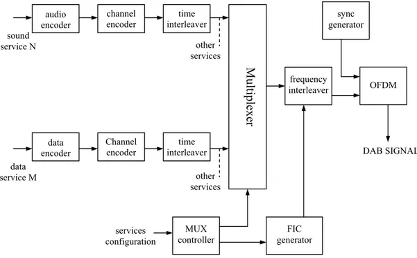
A conceptual block diagram of the DAB system is shown in Fig.3.1. Fig.3.1 (a) shows a conceptual transmitter structure in which each service signal is coded individually at source level and then error protected and time interleaved and then multiplexed into the Main Service Channel (MSC).
audio encoder channel encoder time interleaver Multip lexe r data encoder Channel encoder time interleaver other services other services MUX controller FIC generator frequency interleaver sync generator OFDM DAB SIGNAL sound service N data service M services configuration
CHAPTER 3. OVERVIEW OF DIGITAL AUDIO BROADCASTING
28
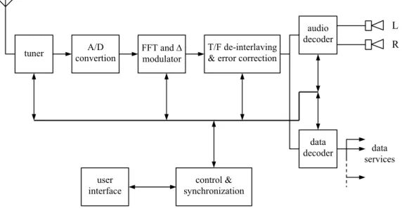
The output of the multiplexer is frequency interleaved and combined with Fast Information Channel (FIC). Finally, very rugged synchronization symbols are added before applying Orthogonal Frequency Division Multiplexing (OFDM) and differential QPSK modulation onto large number of carriers to form the final DAB signal. Fig.3.1 (b) shows a conceptual receiver structure, which performs transmitter operations of Fig.3.1 (a) in reverse order, having selected the wanted DAB ensemble and acquired synchronization.
Figure 3.1 (b): A conceptual DAB receiver structure
3.2.1 Transmission Coding and Time Interleaving
The data representing each service being broadcast are subjected to energy dispersal scrambling, convolutional coding and time-interleaving. If needed, greater protection is given to some source encoded bits than others, following a pre-selected pattern known as the Unequal Error Protection (UEP) profile. The convolutional encoding process contains adding redundancy to the
tuner convertionA/D FFT and ∆ modulator T/F de-interlaving & error correction
user
interface synchronizationcontrol &
audio decoder data decoder data services L R
CHAPTER 3. OVERVIEW OF DIGITAL AUDIO BROADCASTING
29
service data using a code with a constraint length of 7. The average code rate, defined as the ratio between the number of source bits and the number of the encoded bits after convolutional encoding, may take a value from 0.35 (highest protection level) to 0.75 (the lowest protection level). Different average code rates can be applied to different sources, subject to the protection level required and bit-rate of the source-encoded data. General data services are convolutionally encoded using one of the uniform rates while data in the FIC are encoded at the highest protection rate (1/3).
3.2.2 Main Service Multiplex
The encoded and interleaved data are fed to the Main Service Multiplexer (MUX) where for each 24 ms, the data are combined in sequence into the multiplex frame. The combined bit stream is known as MSC, which has a gross capacity of 2.4 Mbit/s. Depending on the chosen convolutional code rate, which can differ from one application to another, this supports a net bit-rate ranging from 0.6 to 1.7 Mbit/s, accommodated in a 1.5 MHz bandwidth DAB signal. The Main Service Multiplexer is the point at which synchronized data from all of the services using the multiplex are brought together.
3.2.3 The Guard Interval
Multipath propagation represents a severe problem for mobile receivers, because its characteristics can change very rapidly with motion of the vehicle. This can cause problems in the receiver because it has to analyze the received signal over a time window corresponding to the symbol period, and the optimum positioning of this time window varies as the receiver moves. Incorrect positioning of the time window can cause ISI in the received signal.
CHAPTER 3. OVERVIEW OF DIGITAL AUDIO BROADCASTING
30
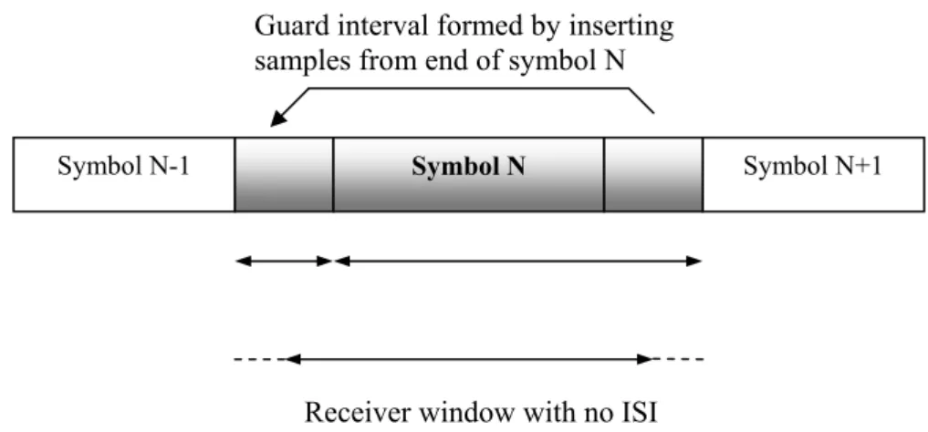
DAB, in common with other OFDM systems, overcomes this problem by adding Guard Interval to each symbol to be transmitted. The duration of the receiver’s symbol window is called the “active” symbol period, which is the reciprocal of the carrier spacing and thus maintains orthogonality, which will be described in Section 3.3. The guard interval extends the total length of the symbol by about one quarter. The DAB system generates the guard interval by inserting it before active symbol and using data identical to that at the end of the active symbol, which avoids discontinuity at the boundary between “active symbol” and guard interval. Fig.3.2 illustrates the use of the guard interval.
Figure 3.2: Symbols with a guard interval
If two identical signals are transmitted from a nearby and a distant transmitter, the receiver would receive two contributions, one of which is delayed compared to the other. However, it will not be able to determine that the delayed signal is coming from a distant transmitter or from a genuine long-delay echo from the nearby transmitter. The receiver will be able to position its time window correctly and decode the received signal successfully, provided that the delay does not exceed the guard interval. Therefore, a number of transmitters can transmit the same signal on the same frequency at the same (or
Symbol N-1 Symbol N Symbol N+1
Receiver window with no ISI Guard interval formed by inserting samples from end of symbol N
CHAPTER 3. OVERVIEW OF DIGITAL AUDIO BROADCASTING
31
nearly same) time. The maximum spacing of these transmitters is limited by the guard interval. Thus DAB allows the use of SFNs to provide wide area coverage.
3.2.4 Transmission Frame and Modes
The actual content of the multiplex is described by the “Multiplex Configuration Information” (MCI) and this is transmitted in a specific part of the “Fast Information Channel” (FIC), since it does not experience the inherent delay of time interleaving which is applied to the “Main Service Channel” MSC. The frame structure of DAB ensemble is shown in Fig.3.3.
Figure 3.3: An example of a DAB Frame structure
The DAB system provides four different transmission mode options which permits the use of a wide range of transmitting frequencies, upto 3 GHz for mobile reception for different purposes. These transmission modes, which are listed in Table 3.1, have been designed to cope with Doppler spread [18] and delay spread [18], for mobile reception in the presence of multipath echoes. It can be seen from Table 3.1 that all transmission modes have the same spectral occupancy. The carrier seperation is a major factor for the
Transmission Frame (24 ms)
Main Service Channel (MSC)
Service 1 Service 2 Service 3 ... Synchronization
Channel
Fast Information Channel (FIC)
CHAPTER 3. OVERVIEW OF DIGITAL AUDIO BROADCASTING
32
immunity of the system to the effects of Doppler spread in the mobile receivers. In general, while Mode I and IV are suitable for terrestrial transmission and for single frequency networks, Mode II and III are suitable for satellite transmission and cable networks.
Table 3.1 : The four different transmission modes of the DAB system
Mode I IV II III
Number of carriers 1536 768 384 192
Carrier seperation 1 kHz 2 kHz 4 kHz 8 kHz
Guard interval duration 246 µs 123 µs 62 µs 31 µs
Nominal maximum transmitter
seperation for SFN 96 km 48 km 24 km 12 km
Nominal frequency range (for
mobile reception) ≤ 375 MHz ≤ 750 MHz ≤ 1.5 GHz ≤ 3 GHz
3.3 Modulation with OFDM
OFDM is a special case of multicarrier transmission, where a single data stream is transmitted over several lower rate subcarriers. OFDM can be seen as either a modulation technique or a multiplexing technique as a solution to the problem of transmitting data over channels with large delay spread [19]-[23]. The major reason for using OFDM is to increase the robustness against frequency selective fading or narrowband interference. In a single carrier system, a single fade or interferer can cause the entire link to fail, whereas in a multicarrier system, only a small portion of the subcarriers will be affected. The concept of using parallel data transmission by means of frequency division multiplexing (FDM) was published in mid 1960s [24], [25]. The idea was to use parallel data streams and FDM with overlapping subchannels, which are
CHAPTER 3. OVERVIEW OF DIGITAL AUDIO BROADCASTING
33
spaced b apart in frequency, each carrying a signaling rate b, to avoid the use of high-speed equalization and to combat impulsive noise and multipath distortion, as well as fully use the available bandwidth. Fig.3.4 demonstrates the difference between conventional non-overlapping multicarrier technique and overlapping multicarrier modulation technique. As shown in Fig.3.4 orthogonal multicarrier modulation technique saves almost 50% of bandwidth. In OFDM, each carrier is orthogonal to all other carriers, and therefore there is no crosstalk between any subcarrier.
For large number of subchannels, the arrays of sinusoidal generators and demodulators required in a parallel system make the system to be unreasonably expensive and complex. The receiver needs precise phasing of the demodulating carriers and sampling times in order to keep crosstalk between subchannels acceptable. Weintein and Ebert [26] applied discrete Fourier Transform (DFT) to parallel data transmission system as part of the Figure 3.4: Concept of OFDM signal: (a) conventional multicarrier technique (b) orthogonal multicarrier modulation technique.
frequency
frequency Saving of the bandwidth
(b) (a)
CHAPTER 3. OVERVIEW OF DIGITAL AUDIO BROADCASTING
34
modulation and demodulation process. In addition to eliminating the banks of subcarrier oscillators and coherent modulators required by FDM, a completely digital implementation could be built around special-purpose hardware performing the fast Fourier transform (FFT), which is an efficient implementation of DFT. Recent advances in very large scale integration (VLSI) techniques enable the making of high speed chips that can perform large size FFT at affordable price. In 1990s, OFDM has been exploited for wideband data communications over mobile radio FM channels, high-bit-rate digital subscriber lines (HDSL, 1.6 Mbps), asymmetric digital subscriber lines (ADSL, 1.536 Mbps), very-high speed digital subscriber lines (VDSL, 100 Mbps), digital audio broadcasting and HDTV terrestrial broadcasting [20], [27]-[30].
3.3.1 OFDM Signaling and Orthogonality
After the qualitative description of the system, mathematical definition of the OFDM signal allows us to see how the signal is generated and gives us a tool to understand the effects of imperfections in the channel.
Mathematically, each carrier can be described as a complex wave:
[ ( )]
( )
j ct c tc c
s t
=
A e
ω +φThe actual signal is the real part of sc(t), and Ac and φc are the amplitude and phase of the carrier. The values of these parameters are constant over the symbol duration period τ. OFDM contains many carriers, therefore the final signal ss(t) can be represented by:
1 [ ( )] 0
1
( )
n n N j t t s N ns t
A e
N
ω φ − + ==
∑
(3.1) (3.2)CHAPTER 3. OVERVIEW OF DIGITAL AUDIO BROADCASTING
35
where ωn = ωo+ n∆ω. If the signal is sampled using a sampling frequency of 1/T, then the resulting signal can be represented by:
1 ( ) ( ) 0
1
(
)
n N j t j n kT s N ns kT
A e
e
N
φ ω − ∆ ==
∑
where τ=NT, ωo=0 without loss of generality.
Now (3.3) can be compared with the general form of the inverse Fourier Transform [29]: -1 2 / 0
1
(
)
N j k N nn
g kT
G
e
N
NT
π ==
∑
Equations (3.3) and (3.4) are equivalent if1 1 2 f NT ω π τ ∆ ∆ = = =
This is the same condition that is required for orthogonality, and therefore maintaining orthogonality enables us to make use of Fourier transform procedures.
The “orthogonal” part of the OFDM name indicates that there is a precise mathematical relationship between frequencies of the carriers in the system. In an OFDM signal, it is possible to arrange the carriers in an OFDM signal so that sidebands of the individual carriers overlap and the signals can still be received without adjacent carrier interference. In order to achieve this, the carriers must be mathematically orthogonal. If the symbol period is τ and the carrier spacing is 1/τ, then all carriers are linearly independent (i.e. orthogonal).
(3.3)
(3.4)
CHAPTER 3. OVERVIEW OF DIGITAL AUDIO BROADCASTING
36
Suppose sp, sq are the signals of different carriers, then the signals are orthogonal if * ( ) ( ) 0 a p q b K for p q s t s t for p q = = ≠
∫
where interval [a, b] is a symbol period.
3.3.2 OFDM in Digital Audio Broadcasting
The digital modulation scheme used in Eureka 147 DAB system is based on 4-differential QPSK OFDM, since it meets the transmission needs of high bit-rate digital signals to vehicular, portable and fixed receiver even under critical reception conditions due to the presence of multipaths [8]. This scheme combines the advantages of wideband and narrowband modulation.
As described in the previous section, the information is divided into a large number of bitstreams, having low bitrates individually, which are then used to modulate individual orthogonal carriers, such that the corresponding symbol duration becomes larger than the delay spread of the transmission channels. By inserting a temporal guard interval between successive symbols, channel selectivity and multipath propagation will not cause inter-symbol interference (ISI). As seen from Table 3.2, N orthogonal carriers, which can be conveniently generated by an FFT process, is known collectively, as a “DAB Ensemble”.
The spectrum of the DAB Ensemble signal is approximately rectangular, Gaussian noise-like, and occupies a bandwidth of about 1.5 MHz. In the presence of multipath propagation, some of the carriers are enhanced by constructive signals, while others suffer destructive interference (frequency selective fading). Therefore, DAB system provides frequency interleaving by a
CHAPTER 3. OVERVIEW OF DIGITAL AUDIO BROADCASTING
37
re-arrangement of the digital bitstream among the carriers, such that successive source samples are not affected by selective fade. When the receiver is stationary, the diversity in the frequency domain is the prime means to ensure successful reception. The time diversity provided by time interleaving provides further assistance to a mobile receiver.
Table 3.2: OFDM parameters for different transmission modes of DAB system
Mode I IV II III
Frame duration 96 ms 48 ms 24 ms 24 ms
Null symbol duration 1297 µs 648 µs 324 µs 168 µs
Guard interval duration 246 µs 123 µs 62 µs 31 µs
Useful symbol duration 1 ms 500 µs 250 µs 125 µs
Total symbol duration 1246 µs 623 µs 312 µs 156 µs
Number of radiated carriers 1536 768 384 192
3.3.3 Multicarrier Allocation in OFDM
OFDM used in DAB assigns the same number of bits and an equal amount of power to all subchannels, regardless of their individual characteristics. This is expected, since OFDM is used in DAB for only broadcasting audio services and related data, without considering the large number of listeners’ conditions. However, if OFDM is intended to be used for a multiuser wireless communications system, for example, the proposed asymmetric PMR system, the problem of adapting the transmit power and bit allocations is crucial. In this way, one may utilize the resources efficiently by adapting the power level and the number of bits to be transmitted according to the channel characteristics of the user.
![Figure 2.1: Breakdown of PMR user community in the UK [1].](https://thumb-eu.123doks.com/thumbv2/9libnet/5621550.111351/24.892.281.669.433.725/figure-breakdown-pmr-user-community-uk.webp)