?>' ÿtî ] ·ν| ’íf.V . Vf ·\ tf f!íñ-t* ‘''Ϊ ■ Φ· ''■*■ í '
■\? f ■^■ί · Μ0· h .-Ш lí .u'i r á i- i ? -f s " t·:| I f ■■
iw? UJ '■í i· ¿ í ' υ ϋ *.,- * — -Α·, ■-V«. ^ 4w) V, V-U. ·ν.* J ,1/ 5 'J üi ' ' f » \ ■·.·''
.^^·· V i l :ê l i í :í' / ί ' ΐ · j ■' liV'íi'Ví-í· ·Γ ‘ ■•■|·^ j. :.>■ - Щ >i.T¿· f.:,.·· n
i
ξ ·] ·^ ; ··| · -ti ;í > . n-■(·τ tú. ЩМ
' í íí.í; i - ' t · » -tí? i j >J- á^y d. ■· W ÇUi.· -Ч ■ - ¿-d. O'J ·:>■. ■■ -Ğ ¡J: (y.
Sd tdií
r »
/ 6 3 7 ^
DESIGN AND IMPLEMENTATION OF A
RADIOLOGICAL IMAGE VIEWING TOOL
A THESIS
SUBMITTED TO THE DEPARTMENT OF COMPUTER ENGINEERING AND INFORMATION SCIENCE AND THE INSTITUTE OF ENGINEERING AND SCIENCE
OF BILKENT UNIVERSITY
IN PARTIAL FULFILLMENT OF THE REQUIREMENTS FOR THE DEGREE OF
MASTER OF SCIENCE
By
Gürhan Keskin
June, 1993
£ 0 2 3 0 7 ?
'"l İ-^, \ I
I certify that I have read this thesis and that in my opinion it is fully adequate, in scope and in quality, as a thesis for the degree of Master of Science.
Asst. Prof. Kem ^Oflazer (Advisor)
I certify that I have read this thesis and that in my opinion it is fully adequate, in scope and in quality, as a thesis for the degree of Master of Science.
I certify that I have read this thesis and that in my opinion it is fully adequate, in scope and in quality, as a thesis for the degree of Master of Science.
rof. Hayrettiıy)l<öymen
Approved for the Institute of Engineering and Science:
Prof. Mehmet l^^iiay Director of the Institute
ABSTRACT
DESIGN AND IMPLEMENTATION OF A
RADIOLOGICAL IMAGE VIEWING TOOL
Gürhan Keskin
M .S . in Computer Engineering and Information Science Advisor: Asst. Prof. Kem al Oflazer
June, 1993
Recent developments in Picture Archiving and Communication Systems (PACS) in clinical environment allow physicians and radiologists to access and assess radiographic images directly through imaging workstations.
In this thesis, an imaging workstation called RADVIEW^ has been designed and implemented for using in a PACS environment in radiology departments of large hospitals.
The main function of RADVIEVV is the archiving of and access to radiologi cal images by maintaining user friendly interactive environment to radiologists. The system can provide rapid access to any or all radiological information as sociated with a patient.
Keywords: Picture Archiving and Communication Systems, Hospital Informa
tion Systems, Radiology Information Systems.
‘ RADVIEW stands for ’’ Radiological Image Viewing Tool.” Ill
ÖZET
BİR RADYOLOJİK GÖRÜNTÜ İZLEME PROGRAMI
TASARIMI VE YAZIMI
Gürhan Keskin
Bilgisayar ve Enformatik Mühendisliği, Yüksek Lisans Danışman: Yard. Doç. Dr. Kem al Oflazer
Haziran, 1993
Tıp alanında, görüntü arşivleme ve iletişim sistemlerinde son zamanlarda meydana gelen ilerlemeler, doktorlara ve radyologlara radyolojik görüntüleri iş istasyonları (görüntü istasyonları) yolu ile incelemelerine olanak tammaktadir.
Bu tezde, büyük hastanelerin radyoloji kliniklerinde kullanılmak üzere, iş is tasyonlarının görüntü istasyonları olarak kullanımına olanak tanıyan, bir rady olojik görüntü izleme programı tasarımı yapıldı ve gerçekleştirildi.
RADVIEW^ ismi verilen programın ana kullanım amacı, tıbbi görüntülerin saklanmasını ve erişimini, radyologlara kullanıcı ile dost bir ortamda sun masıdır. Ayrıca bu program ile, bir hastanın radyolojik bilgilerine ve görüntülerine hızlı bir erişim de sağlanmaktadır.
Anahtar Sözcükler: Görüntü Arşivleme ve iletişim Sistemi, Hastane Bilgi Sis
temi, Radyoloji Bilgi Sistemi.
"RADVIEVV, Radyolojik görüntü izleme anlamına gelen, İngilizce ” Radiological Image RieHİRg” kelimelerinden türetilmiştir.
ACKNOWLEDGMENTS
I would like to express my deep gratitude to my supervisor Dr. Kemal Oflazer for his guidance, suggestions, and invaluable encouragement throughout the development of this thesis. I would also like to thank to Dr. Aral Ege and Prof. Hayrettin Koymen for reading and commenting on the thesis. I owe special thanks to Prof. Mehmet Baray for providing a pleasant environment for study. I am grateful to my friends for their infinite moral support and help.
Contents
1 Introduction 1
2 PACS 4
2.1 Image A cquisition...'... 7
2.2 Image Display and O u tp u t ... 7
2.3 Image Database and S tora g e... 8
2.4 Networking and C om m u n ication s... 9
2.5 PACS in the Future... 10
3 The Radiological Image Viewing Tool 11 3.1 Using RADVIEW in a Radiology D e p a rtm e n t... 13
3.2 The User Interface 15 3.2.1 Login to the System 18 3.2.2 Patient Registration and Selection... 21
3.2.3 Defining a New V i s i t ... 21
3.2.4 Radiological Operations 23
3.2.5 Image Set, Detailed Image Study and Animation 28
3.2.6 Reports 33
4 Implementation of the System 37
4.1 The system en viron m en t... 37
4.2 The Structure of Radiological Information of Patients and Database... 39
4.3 The Image Database Structure and IMDIR C l a s s ... 42
4.4 The Image Processing Methods and IMAGE C la ss... 45
4.5 Fast Report G e n e ra tio n ... 47
4.6 Communication Among Medical Staff 48 4.7 Security in Using RADVIEW and Accessing Patient Radiologi cal D a t a ... 49
4.8 Turkish Font Support 50 4.9 Utility Programs ... 52 4.9.1 R a d b a s e ... 52 4.9.2 A d d u s e r ... 52 4.9.3 Orapasswd... 54 4.9.4 M a ile r ... 54 5 Conclusion 55 CONTENTS vii
List of Figures
2.1 A Simple P A C S ... 6
3.1 Patient Study in a Radiology Department 13
3.2 The Entity Relationship Model of Radiological Patient Informa tion ... . . . 15 3.3 Execution Flow Diagram of RADVIEW S c r e e n s ... 17
3.4 Login to the System 19
3.5 Patient S e le c t io n ... 20
3.6 The Personal Information of a Patient 22 3.7 The Visits of a P a t ie n t ... 24
3.8 The Visit Information 25
3.9 The Findings About a Visit . . . ... 26
3.10 The Radiological Operations of a V i s i t ... 27 3.11 The Radiological Operation Information 29
3.12 The Image Set 30
3.13 The Detailed Image S t u d y ... 31
3.14 The Observations About an Image or Image S e t ... 34
3.15 The Animation of Images in an Image Set 35
LIST OF FIGURES IX
3.16 A Sample R e p o r t ... 36
4.1 The Access to Radiological Patient In fo rm a tio n ... 39
4.2 The image directory s tru c tu re ... 43
4.3 A Sample Report P r o t o t y p e ... 48
4.4 The Report Tree Constructed After Parsing the Text in Report P r o t o t y p e ... 49
4.5 Possible Reports That can be Generated from the Report Tree . 50 4.6 Mail Utility of RADVIEW ... 51
Chapter 1
Introduction
Today computers are used in many areas all over the world. Electronics and computer industry are developing at an ever increasing rate. As a result of such developments, it is possible to use computers in medicine, to collect, store, pro cess, retrieve and communicate patient care and administrative information, for all hospital oriented activities within the context of a Hospital Information Systems (HIS). The objective of a HIS is the functional integration of all hos pital information and the efficient management and use of this information to improve the quality of patient care and hospital services [3].
With the emergence of computer use in hospitals, it was recognized that they might support handling of the information in the radiology department as well. Perhaps because of the limited support offered by HIS, the concept of Radiology Information System (RIS) has emerged. Archiving medical images and accessing them fast is the one of the main research areas under the concept of RIS.
The concept of archiving medical images in digital form and distributing them to video monitors for review was conceived in early I980’s. The word PACS was unofficially adopted as the acronym for Picture Archiving and Com munication Systems, in January 1982 during the first International Conference and Workshop on Picture Archiving and Communication Systems for Medi cal Applications in Newport Beach, California [11]. PACS attempts to utilize computing power to increase the efficiency of the radiology department in cost- effective manner; and in this respect it can be considered as a subsystem of a RIS.
A PACS provides the following functionalities [9, 2]
• acquisition of medical images, • image database and storage, • image display and output, and • networking and communications.
CHAPTER 1. INTRODUCTION
Image acquisition refers to the capture of medical images from the patients
by means of imaging devices and scanners. Image display and output refers to the image display stations with relevant software and output devices like printers, plotters etc. Image database and storage is another important com ponent that stores images for long and short term usages. Networking and
communications is the heart of a PACS. It provides all the connections among
the devices in the system for fast image transmission.
The idea to realize a PACS was triggered by two developments: on the one hand the introduction of digital modalities that could directly supply im ages that could be handled by information technology, and on the other hand developments of information technology like storage facilities, networks, high resolution displays and software [-3]. Today, it is possible to store a few giga bytes on magnetic disks, tens of gigabytes on optical disks and hundreds of gigabytes on optical tapes. It is also possible to transfer tens of megabytes in a second and get very high quality pictures on video displays.
The developments of information technology enabled people to develop in PACS system and applications. Such developments of PACS in clinical environ ment allow physicians and radiologists to examine radiographic images directly through imaging workstations. The development of medical workstations was primarily oriented toward the development of convenient tool for rapid display of images.
In this project, a tool (RADVIEW ) to store and display medical images has been designed and implemented for imaging workstations used in radiology departments of large hospitals. RADVIEW is the image display part of a PACS. Radiologists view medical images and write their examination reports. The image display component of a PACS enables radiologists to view medical images easily and, complete their examination reports quickly. So it is possible
to say that image display performance of a PACS directly influences the success of a PACS.
RADVIEW has three main features :
1) a user friendly, efficient, interactive user interface environment,
2) patient information storage and access, and 3) image database access.
In order to design such a tool, one of the most important consideration is to make a user friendly, interactive user interface. Although there are some hybrids, most graphical user interfaces (GUIs) consist of three major com ponents: a window system, an imaging model and an application program interface. In this project the X-window system^ has been used to implement the user interface of RADVIEW with its own imaging model.
Since patients are the main information-being component, the information about patients containing patient’s personal information and radiological in formation including visits, radiological operations, examination reports has to be maintained in a database.
RADVIEW has some other features like hierarchical patient study, ability to communicate among medical staff in the hospital, security in accessing patient’s radiological information and medical images, efficient fast reporting.
This thesis explains the project steps and contains four more chapters. Chapter 2 describes a PACS. Chapter 3 describes the most important proper ties of RADVIEW and its user interface. Chapter 4 describes the implemen tation of RADVIEW. Chapter 5 presents the conclusions.
CHAPTER 1. INTRODUCTION 3
PACS - Picture Archiving and
Communication Systems
Chapter 2
The importance of functions of the radiology departments in patient care and diagnosis can not be overeupheraized. In medicine, radiology departments play very important role, and in the future this role will certainly maintain its importance by for example, every year in a large scale hospital, the radiology department is visited by about 250,000 patients and one million images in various modalities are generated.^
Radiology departments have some responsibilities to achieve. The World Health Organization at Geneva (W HO) published a manual called Basic Ra
diology System in 1985. According to this manual, all radiology departments
should keep :
• a register containing names, personal details of patients, type of exami nations made and diagnosis,
• films of each patient for at least five years, and
• details of number and size of films used each month for statistical pur poses.
According to WHO, the records contained in patient register are very im portant and can be helpful in tracing medical images of a patient and her'·^ 'These numbers are radio-diagnostic workload of Hacettepe University Hospital, Ankara in 1989 [12].
CHAPTER 2. PACS
diagnosis.
In order to keep patient records and help radiologists to examine images, computers have started playing an important role. Recent developments in electronics and computer technologies has been instrumental in the initial ization of the Picture Archiving and Communication Systems (PACS), which allowed the employment of computers in radiology to archive and access patient records, and medical images.
The concept of PACS emerged in early 1980’s. A PACS provides the fol lowing functionalities:
• storage of digitized images being produced by different imaging modali ties in central image database (archiving),
• access to images generated by different modalities by means of worksta tions that also offer image processing facilities (retrieval),
• fast transmission of images among from the acquisition devices to image databases and from image databases to workstations (communication).
Introduction of digital modalities that could directly supply images and recent developments in image acquisition, image compression, storage, image display, image communication and image database structures have played very important role in realization of the PACS idea. Therefore, PACS can be also defined as an integration of knowledge in the fields of image formation, image processing, communication engineering, teleradiology, display station engineer ing, database engineering and software engineering.
A PACS accepts pictures or images, possibly with associated text, in digital form and then stores and distributes them over a network. The components of a PACS include control computers and a communication network, interfaces to imaging devices, storage media display stations and printers as shown in Figure 2.1 .
A PACS system can be divided into four main parts:
• image acquisition,
CHAPTER 2. PACS
(highs p eedn etw ork" !
r IMAGING DEVICES 1 1 r n □ □ □ □ □ □ □ □ □ □ □ □ SCANNERS V________ J (im ag e ACQUISITION ) (im ag ed isplay ] VIEWING STATIONS ( IMAGE DATABASE ) ( OUTPUT
IMAGE OUTPUT DEVICES
/ \ !
---W i r i i i i r PRINTERS
/ V
• image database and storage, and • networking and communications.
2.1 Image Acquisition
The basic goal of the image acquisition subsystem is to deliver all relevant image data from a radiological imaging device (CT, MRI, CR, etc.) to storage devices from which all clinically relevant patient images are immediately and easily accessible [17]. Digital radiological images are acquired from three sources:
1. the inherently digital modalities such as CT and MRI, 2. laser film digitizers, and
.3. computed radiography (CR) units.
A direct integration of acquisition devices to PACS is very important opera tionally [6].
Digital images can be acquired by using four possible mechanism [10]:
1. a digital network transmits images directly from CT, US, or MR to the archival computer system and to storage devices,
2. a magnetic tape unit reads image acquired by imaging modalities located either inside or outside the department which are not connected to the network, (i.e., a CT study of patient done in another hospital)
3. a high resolution laser film digitizer converts conventional X-ray films to a digital format that maintains the diagnostic quality of the original film, and
4. a CR system acquires a conventional X-ray image in digital format.
CHAPTER 2. PACS 7
2.2 Image Display an4 Output
Radiologists commonly view diagnostic films in a reading room on light-boxes or alternators. The latter are lighted panels that can store up to 200 films.
CHAPTER 2. PACS
which are rotated into view by pressing a foot pedal. The standard by which PACS display stations will be judged is the alternator, which displays up to eight images simultaneously, changes a set of images within seconds, and deliv ers the very high resolution of the film display medium. To change the images’ apparent magnification, the radiologist moves nearer to the film or uses a mag nifying glass. To see the details in a dark area of the film, the radiologist holds it in front of an incandescent lamp called hot lamp.
To rival the alternator, the digital viewing station must display images of high quality, several at a time and be able to change them rapidly as well as provide simple image processing. The basic components required are one or more video monitors, video memory and an interface to image network.
Image display stations can be located in the radiology department, on pa tient floors and in offices of referring physicians. Recent studies show that the resolution of video monitors depends on the examination type and the radiol ogist doing the reading. The video monitors can have a resolution of 512, 1024 and 2048 lines. The 512-line monitor is inexpensive and can be used for CT, MR, US and conventional x-ray images involving gross abnormalies, such as those often seen in the intensive care unit. The 2048-line monitor is expensive and used for displaying very high resolution radiological images, most often used in the radiology department. At the intermediate level, 1024-line moni tor which is widely available, and costs about one-fifth as much as a 2048-line monitor, has adequate resolution [10, 20].
2.3
Image Database and Storage
The storage and retrieval of radiographic images have always played a critical role in clinical radiology. Storage systems that allow easy access to patient images improve patient care by providing information to the radiologist, tech nologist and primary physician. Radiogra,phs recalled from storage are used to (1) provide better patient examination planning and execution, (2) assist in radiological interpretation of current images and (3) further research and teaching radiology [11].
The introduction of PACS has not changed the role of image storage. What has changed, however, is the ability to provide access to patient information
CHAPTER 2. PACS Storage Media Retention Period storage Capacity Retrieval Time
Magnetic Disks 1 day - 1 month
tens of
GigaBytes few seconds Optical Disk
Juke Boxes (online) 1 month - .3 years
hundreds of
GigaBytes tens of seconds Optical Tape
Storage (online) 3 years and above TerraBytes few minutes
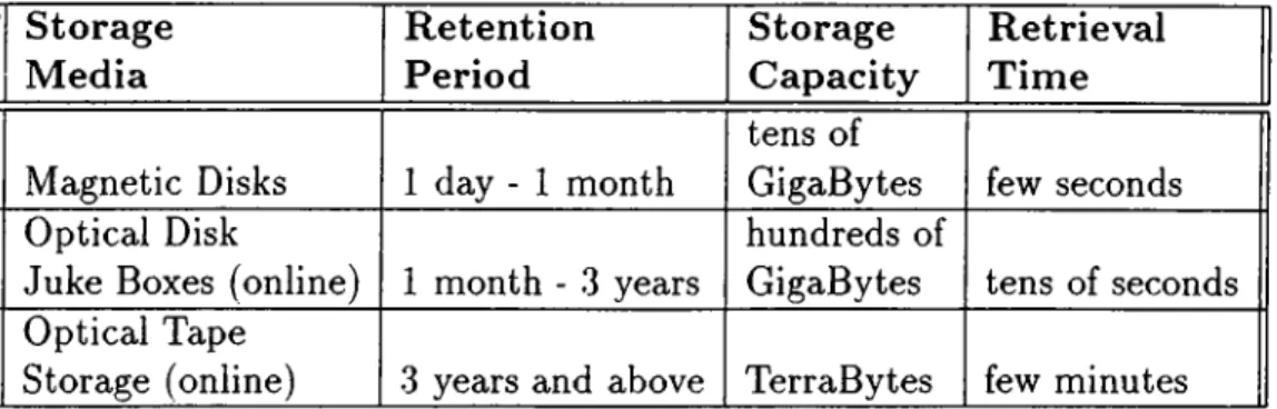
Table 2.1. The Storage Level Hierarchy for PACS Data
quickly and automatically. Computers and their storage devices offer the po tential to retrieve digital images from a very large image database with no operator intervention. It is the enormity of this database that must be consid ered in establishing digital image storage.
For every thousand beds, a large hospital generates about three gigabytes of picture data per day. The storage subsystems in a PACS must be able to hold all this data as well as allow convenient and rapid access to them. To keep speed up and cost down, PACS database archive system will likely be multilevel hierarchical units containing a mixture of storage technologies. Their structure would conform to the logical organization of current archives, which arrange film into immediate, short-term and long-term storage categories [20].
Digital image storage relies on the fast magnetic disk arrays and an optical disk library. Magnetic disks are more expensive in terms of bytes/dollars and are used in short-term image archiving, whereas the optical disk library has a very large capacity, costs less and is used for long-term archiving. Table 2.1 [14], shows the leveled concept of image storage with approximate retention periods and retrieval times. These two types of storage devices are controlled through .software to regulate the flow between short-term and long-term archival [10].
2.4
Networking and Communications
Since a PACS contains several devices, communication among these devices is a very important aspect. After a digital image has been acquired, via a
CHAPTER 2. PACS 10
digital modality like computed radiography or through film-digitization, it must be transmitted to a storage device for archiving and later be available for retrieval display, manipulation and review. This requires consideration of a digital communication network for images and image-related data.
The timely communication of digital medical images requires a wide band width due to the enormous amount of data in each image or set of images for PACS to be useful to the radiologist, it is estimated that a CR image (of size 2Kx2K, in 8 bit gray format, 4MB) should be transferred within network in less than one second [4].
Currently, using the Ethernet^ under optimal conditions, transmitting a 4MB CR image within the same building takes about ten seconds, which is too slow for routine clinical practice. The emerging FDDI (Fiber optic Dis tributive Data Interface) has the potential of improving the performance to five times better. Proprietary high speed imaging network is now available and can transmit a 4MB CR image in one second, satisfying most clinical ap plications. PACS digital network design needs a careful analysis of clinical requirement since many communication processes occur simultaneously in a PACS network [10].
2.5
PACS in the Future
Radiologists’ resistance to the digital hospital may be the greatest obstacle to implementing PACS. The new technology will force a change to their routine, requiring a lot of their time initially to learn to use the new image-handling methods. Some radiologists even see a wide distribution of diagnostic images as a thereat to maintaining the highest-quality patient care since it will help physicians sidestep to radiologist and make their own readings.
The technology for integrating digital information handling systems in hos pitals is available, but it is too expensive for immediate introduction. The cost is decreasing and technology is improving, however, the explosive growth of hospital information will compel the development of digital systems [20].
Chapter 3
The Radiological Image Viewing Tool
In a typical radiology department, images are stored and maintained manually. Images taken from various modalities (computed tomography, x-ray, etc.) are stored in a patient folder. When the radiologist is ready to examine the image, she requests the image from the cvrchive, schedules time to view the image, views the image, possibly views previous (older) images, discusses the case with the referring physician and writes the examination report.
The examination report is placed with the film in the patient folder, and the folder is, once again, filed away. This process results in much wasted time and wasted resources. Images that are lost, or of low quality must be resched uled or retaken. Because the filing system is manual, the retrieval time of the image is, in the best case, on the order of minutes. The lack of sufficient film reading stations makes it difficult to schedule time for the examination of the image which in turn makes it harder for the referring physician to obtain the results in a timely manner. It is difficult to obtain a copy of the image with out the need for a digitized hard-copy to be generated on request. Additional information for a patient is difficult to obtain without requesting that informa tion be retrieved from other hospi al systems. Therefore, the automated PACS attempts to integrate all of the functions of the manual radiology department into a networked facility operating in a systematic way [14].
This chapter describes a liadiologicai Image Viewing Tool called RAD- VIEW developed in the thesis. This tool is designed and implemented as the
CHAPTER 3. THE RADIOLOGICAL IMAGE VIEWING TOOL 12
image display component of a PACS project called RAGARIS^ [12].
The main functions of the RAGARIS project are the capture, archival of and access to medical images as any other PACS. The system will be able to interface with a variety of medical imaging devices, and provide rapid access to any or all radiological information associated with a patient [12].
By using RADVIEW radiologists can achieve the same tasks in manual radiology departments described above. Some of the properties of RADVIEW are as follows:
• More than one medical images can be simultaneously viewed on the screen with the help of certain image processing features (contrast and intensity enhancement, scaling, histogram equalization etc.),
• Images from various types of modalities (CT, MRI, US) can be examined and processed,
• Standard observations and findings can be written rapidly by using some predefined report prototypes,
• Images belonging to a radiological operation can be animated (continuous display),
• Radiologists and physicians can communicate by means of a mail utility, • Security in accessing patients’ radiological information and the medical
images is provided,
• New patient registration and hierarchical patient study is provided, • Reports and images can be generated on hardcopy devices, and • Turkish and English fonts are supported.
In this chapter RADVIEW will be examined in detail. In the following subsections, these properties, and functionalities will be described.
'Ragaris stands for ’’ RAdyolojik Görüntü AR^ivleme ve İletişim Sistemi” , Radiological Image Archiving and Communication System.
CHAPTER 3. THE RADIOLOGICAL IMAGE VIEWING TOOL 13 (PATlEm ·) I RADIOLOGY
i
REGISTRATIONi
OPEN a VISIT(
OPEN a RADIOLOGICAL OPERATION
IMAGE A C Q U IS IT IO N
RADIOLOGIST
(
DETAILED IMAGE STUDY
I
FINDINGSI
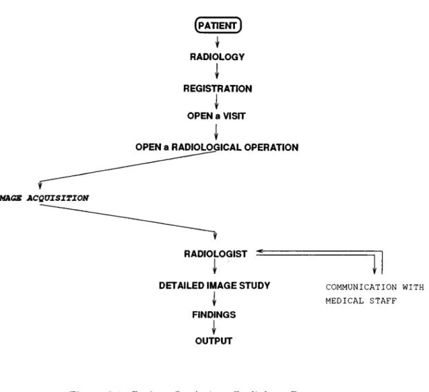
OUTPUT COMMUNICATION WITH MEDICAL STAFFFigure 3.1. Patient Study in a Radiology Department
3.1
Using R A D V IE W in a Radiology Department
As shown in Figure 3.1, the organization of a patient study can be done in a radiology department using RADVIEW with in the following steps:
1. A patient applies to radiology with his request form from the referring physician (or this form can be sent on-line if referring physician’s computer is connected to the network).
2. The patient is registered to the system, if she has not yet been registered.
3. The patient’s visit information and requests are entered by opening a new visit for this patient.
CHAPTER 3. THE RADIOLOGICAL IMAGE VIEWING TOOL 14
operation is defined, and more detailed, more specific information about the operations defined are entered.
5. The patient is sent to the acquisition division of the radiology depart ment. The technicians in this division acquire the images of the patient as noted in her visit and radiological operations according to requests from the referring physician. They can (optionally) enter some sort of textual data for the corresponding radiological operation.
6. After the acquisition process, the images are available in image storage database and they are ready to be read by radiologists.
7. A radiologist examines the images of each modality corresponding to a radiological operation with the help of image processing functions. In this step the radiologist can make comparisons among the multiple images, and can see all the images belonging to the same radiological operations continuously by selecting the animation option.
8. Radiologists can enter their findings using RADVIEW at the single image level, at the multiple image, in other words, image set or radiological operation level, and in visit level (three level hierarchy). They can write their findings and observations by means of the fast report writing utility.
9. Radiologists can communicate with referring doctor or other medical staff for consultation or other purposes by using the mail utility in RADVIEW.
10. An image can be saved to an externally specified path in PGM (Portable Gray Map) format for sending it to another hospital or for using for other pur poses. This image can be seen on other conventional image displayers available.
11. Reports can be taken from the printers available in the system.
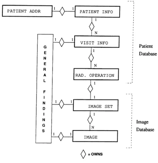
A patient’s radiological information can be accessed in a hierarchical man ner. This hierarchy is shown in Figure .‘j.2 as an entity relationship model. The information about each patient contains the patient’s personal information in cluding the address. For each patient a visit is defined when she applies to the radiology department. Under each visit one or more radiological operations are opened. For each different type of modality request, a new radiological
CHAPTER 3. THE RADIOLOGICAL IMAGE VIEWING TOOL 15
0 =
Patient Database Image Database OWNSFigure 3.2. The Entity Relationship Model of Radiological Patient Information
operation is defined. There is only one image set (a number of images of the same modality) for each radiological operation. Radiologists can enter their observation, examination reports, etc., at the single image level, at the image set level and at the visit level.
3.2
The User Interface
In the design of RADVIEW , a special emphasis has been placed on the design of the user interface to allow clinicians with minimal or no computer manipulation skills to use complex analysis tools. In designing the graphic user interface of RADVIEW, where the functions are activated through graphic icons and
CHAPTER 3. THE RADIOLOGICAL IMAGE VIEWING TOOL 16
selectable menus, and triggered through mechanical devices such as a mouse, the goal was to create a tool that rapidly becomes transparent to the user allowing her to achieve complex tasks with the minimal amount of technical training [15].
I have developed the user interface of RAD VIEW by using the XView^, a toolkit of X-window system. I have utilized from XView objects like frames,
canvases, panels, panel items (buttons, text and numeric items), list items, menus and text windows. To achieve tasks like patient selection, opening a visit,
image viewing, etc., different screen designs have been performed. There are a total of thirteen screens in the program accessed via execution flow diagram shown in Figure .3.3. The user can always return to the point from where the current screen has been called. The user can also return to the screen HASTA
BELİRLEME from every screen in the program by means of a general menu
available on every screen’s panel. This menu contains some other items to exit from RADVIEW , to call RAD VIEW ’s mailer, to close the current screen and to return back where the current screen has been called.
Patients, their visits and radiological operation of each visit can be selected by using the list items. User can see all the alternatives on the screen and by using the mouse, points one of them. By pressing the left mouse button, she can pass to the next window in the program. Although, visits and radiological operations can only be selected by means of list items, a patient can be selected in three different ways:
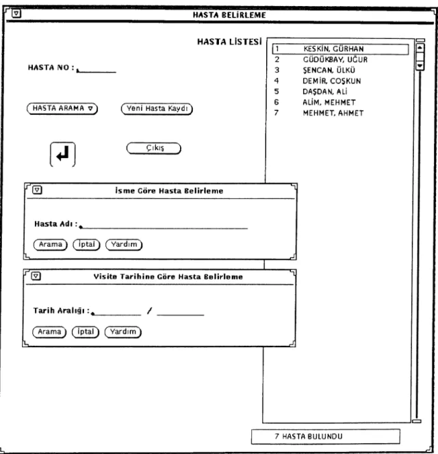
1. user directly enters a patient’s access number, 2. user specifies the patients name, and
3. user specifies the visit date.
In the last two methods, all the patients conforming the specified query, are listed in the patient ID number order. Patient selection is performed by moving the pointer over the patient of interest and clicking the left mouse button.
“ XView stands for X window system based Visual/Integrated Environment for Worksta tions and it is a trademark of Sun Microsystems, Inc.
CHAPTER 3. THE RADIOLOGICAL IMAGE VIEWING TOOL 17
RADVIEW
Figure 3.3. Execution Flow Diagram of RADVIEW Screens
Information about visits and radiological operations, findings and observa tions at the visit level, at radiological operation level and at single image level, are all entered by using text windows. These windows allows user to manipu late text entered from the keyboard. Text can be recorded to the database by only pressing a mouse button while pointer is over the Kayıt (Save) button.
All the images of a radiological operation displayed side by side in a grid in iconic form, when user selects a radiological operation. The user can begin the detailed image study of an image by moving the pointer over the image icon of interest and by pressing the middle mouse button.
In detailed image study screen,The user can apply various type of operations and image processing on images to aid in the diagnosis. Some of the operations available are as follows:
CHAPTER 3. THE RADIOLOGICAL IMAGE VIEWING TOOL 18
• Pixel replication zoom, (activated by selecting an item from a pull-down menu)
• Bilinear interpolation zoom, (activated by selecting an item from a pull down menu)
• Rotation of an image by a multiple of 90 degrees, (activated by selecting an item from a pull-down menu)
• Contrast and intensity changes, (activated by using slider items) • Refreshment of the screen, (activated by pressing a panel button) • Histogram generation, (activated by pressing a panel button) • Histogram equalization, (activated by pressing a panel button)
• Computation of the distance of two points, (activated by pressing a panel button)
• Computation of the area of rectangular or polygonal regions, (activated by selecting an item from a pull-down menu after the region selection) • Video reversal, (activated by pressing a panel button) and
• Region cutting, (activated by pressing a panel button after the cut region selected)
So far I have summarized some of the user interface concepts. The user interface of RADVIEW will be explained in detail in the following sections.
3.2.1
Login to the System
As shown in Figure 3.4, before starting to use the program, each user should enter her username and password so that she can take the permission.
RADVIEW searches a user database to check whether the user has per mission to use it or not. If she has the permission, then program sets the user’s rights which are read from the same user database. If a valid user- name/password pair is entered, then program passes to the next screen in order to register or select a patient shown in Figure 3.5.
CHAPTER 3. THE RADIOLOGICAL IMAGE VIEWING TOOL 19
W RADVIEW
BİLKENT ÜNİVERSİTESİ HASTANESİ
radyoloji
iş
istasyonu
Kullanıcı : GÜRHAN
Şifre: ^
( gıkı? )
Ik.
Figure 3.4. Login to the System. User enters its username and password in order to login to the program.
CHAPTER 3. THE RADIOLOGICAL IMAGE VIEWING TOOL 20
HASTA BELİRLEME
J
Figure 3.5. Patient Selection. Patients Cciri be selected in three ways : by specifying the patient’s access number, name or visit date.
CHAPTER 3. THE RADIOLOGICAL IMAGE VIEWING TOOL 21
3.2.2
Patient Registration and Selection
The screen shown in Figure 3.5, is used to select a patient of interest or to register a new coming patient to the radiology department.
R e g is te r a P atien t : In order to register a patient the Yeni Hasta Kaydı
(Patient Registration) button is pressed, and then a new empty screen as shown
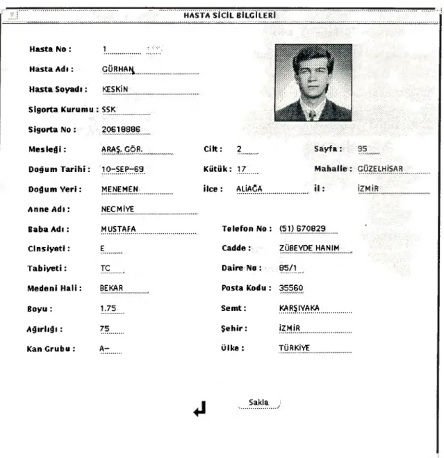
in Figure 3.6 appears. Each patient has a patient access number which is given when the registration screen appears. In order to register a patient, at least, her name and surname fields must be set. This is the necessary condition for registration operation. If one of the name or surname fields is empty, then it is not possible to register a patient. When the user tries to save information by pressing Kayıt button, a warning message appears on the screen to remind user this condition. It is also possible to put a small picture of a patient on the screen by means of a scanner if one is available. This allows radiologists to remember the patient easily.
P atien t S election : There are three different ways for selecting a patient of interest. In the first way, user directly enters the patient’s access number, in the second way the name of the patient is specified and in the last method, the visit date of the patient is given. If the patient’s access number is not valid, then a message appears on the screen to warn the user. In the last two methods, all the patients conforming the specified query, are fisted in the patient’s ID order. Patient selection is performed by moving the pointer over the patient of interest and clicking the left mouse button. If the patient is selected successfully then the next screen shown in Figure 3.7 cippears on the screen.
3.2.3
Defining a New Visit
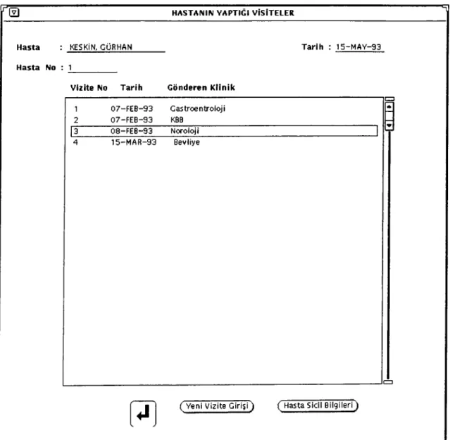
After a patient is selected, the screen shown in Figure 3.7 appears. The user can examine previous visits or define a new visit. In order to select a visit, the pointer is moved over the corresponding visit on the list, by pressing left mouse button. Then the right mouse button is pressed and a menu is displayed hav ing the menu items Vizite Bilgileri (Visit Informations), Bulgular (Findings),
CHAPTER 3. THE RADIOLOGICAL IMAGE VIEWING TOOL 22 HASTA SİCİL BİLGİLERİ Hasta No : Hasta A d ı: Hasta Soyadı: Sigorta Kurumu : 1 GÜRHA^_ KEŞKİK-SSK Sigorta No ; 20618086
M esleği: ARAŞ. GÖR. _____ C ilt: 2____ Sayfa: 95:_;v
Doğum T a r ih i: 10-SEP-69 Kütük: 17 Mahalle : GÜ2ELHİSAR
Doğum Y e ri: MENEMEN: İlce: ALİAĞA i l : İZMİR
Anne A d ı: NEGMİVE
Baba A d ı: MUSTAFA Telefon No : (51) 870829 *
C in siye ti: E· Cadde: ZÜBEVDE HANIM
T a b iy e ti: TC Daire No : 05/1 ;
Medeni H a li: BEKAR ^ Posta Kodu : 35560
Boyu ; 1.75: Sem t: KARŞIYAKA
A ğ ırlığ ı: 75 Ş e h ir: İZMİR
Kan Grubu : A - ülke : TÜRKİYE
Sakla
Figure 3.6. The Personal Information ot a Patient. Patient number is given automatically. In order to register a patient to the radiology department her name and surname must be set. "
CHAPTER 3. THE RADIOLOGICAL IMAGE VIEWING TOOL 23
and Rad. Muayeneler (Radiological Operations) to reach the visit information, findings, and radiological operations of the patient.
When Visile Bilgileri item is selected, then the a new screen of Figure 3.8 appears and the visit informations displayed. In this page it is possible to update all the values of fields by pressing Sakla (Save) button if the user has update rights. It is possible to see findings and radiological operations from this screen by pressing Bulgular and Radyolojik Muayeneler buttons respectively.
When Bulgular item is selected, then a new screen in Figure 3.9 is displayed and all the findings related to this visit can be seen. The findings written in this screen are the general observations or the results of the examination about all the radiological operations of the visit.
The Rad. Muayeneler item invokes the screen in Figure 3.10 and lists all the radiological operations belong to selected visit.
In order to open new visit Yeni Visile Girişi (Open a New Visit) button is pressed. A new screen in Figure 3.8 appears on the screen. In this screen, user can enter the referring physician, receiving physician, referring clinic and all of the requests. The information is saved to the database by pressing Sakla button. At this time Bulgular and Radyolojik Muayeneler buttons are inactive since there is no findings and radiological operations yet.
If Hasta Sicil Bilgileri (Patient’s Personal Informations) button is pressed then all the information of a patient is displayed including her address and picture as shown in Figure 3.6.
3.2.4
Radiological Operations
The patient’s radiological operations that belong to selected visit are listed in the screen shown in Figure 3.10. The selection of a radiological operation is the same as selection of a visit, the pointer is moved over the corresponding radiological operation on the list by pressing left mouse button. Then the right mouse button is pressed and a menu is displayed having the menu items Rad.
CHAPTER 3. THE RADIOLOGICAL IMAGE VIEWING TOOL 24
0 HASTANIN YAPTIĞI VİSİTELER
Hasta : KESKİN, GÜRHAN Tarih : 15-MAV-93
Hasta No : 1
Vizite No Tarih Gönderen Klinik
1 07-FEB-93 Gastroentroloji 2 07-FEB-93 KBB
Q8-FEB-93 Noroloji
15-MAR-93 Bevliye
( Yeni \/izite G irişi) ( Hasta Sicil Bilgileri)
CHAPTER 3. THE RADIOLOGICAL IMAGE VIEWING TOOL 25
VİZİTE BİLGİLERİ
Hasta : KESKİN. GÜRHAN
Hasta No : 1
Tarih : 15-MAY-93
Vizite No : 3 Vizite Tarihi : 08-FEB-93
Gönderen Doktor : 2 SUKAN, ESER ( Dr. Listesi v ) Gönderen Klinik : Nöroloj^
Kabul Eden Doktor: 4 ATEŞ, AHMET ( Dr. Listesi s ı) ( Klinikler
Kafatası MRI grafisi rica ediyorum.
üst açKj^an 3 er derece aralıklı 18 görüntü gerekmektedir. Saygılarımla
( Bulgular ) ( Sakla ) ( Radyolojik Muayeneler^
Figure 3.8. The Visit Information. The referring physician’s requests are entered from this screen in the radiology department. These requests can also be sent by online from the referring physician’s computer if it is connected to the network.
CHAPTER 3. THE RADIOLOGICAL IMAGE VIEWING TOOL 26
Ft VISITE GENEL BULGULARI
Hasta : KESKİN, GÜRHAN
Hasta No : 1
Tarih : 15-MAY-93
Gönderen Klinik : Nöroloji
Gönderen Doktor : SUKAN, ESER
Giriş Tarihi : 08-FEB-93
Bulguyu giren : ATES, AHMET
Yapılan genel visite incelemesi sonucu önemli bir bulguya rastlanmamistir. A. Ate^
( Sakla )
Figure 3.9. The Findings About a Visit. The radiologist can enter her general findings about the visit which may contain one or more radiological operation.
CHAPTER 3. THE RADIOLOGICAL IMAGE VIEWING TOOL 27
RADYOLOJİK MUAYENELER T
Hasta KESKİN. GÜRHAN Tarih : 21-JUN-93
Hasta No : 1
Mua. no Tarih Gönderen Klinik Radyolog Modalite
ПП
08-FEB-93 Nöroloji SUKAN, ESER MRI 1 A
( Yeni Muayene A ç)
Figure 3.10. The Radiological Operations of a Visit. Л visit rnciy contain one or more radiological operation according to requests made by referring physician. For example, for each different modality requests a new radiological operation is defined.
CHAPTER 3. THE RADIOLOGICAL IMAGE VIEWING TOOL 28
Set) to reach the radiological operation information, and image set respectively.
If Rad. Mua. Bilgisi is selected then the screen in Figure 3.11 appears containing the information about the radiological operation. In this screen,
Sakla button is inactivated in order to prevent any changes on this screen.
If Görüntü Seti button is pressed then all the images acquired in this radi ological operation are displayed in small icons as shown in Figure 3.12.
In order to define a new radiological operation Yeni Muayene Aç (Open
a New Radiological Operation) button is pressed and screen in Figure 3.11
appears. In this screen the name of the radiologist and detailed, more spe cific information on radiological operation can be written and inserted to the database by pressing the Sakla button. All information inserted in this screen can not be modified once more when return button pressed. This is reminded to the user by giving a warning message when return button is pressed.
3.2.5
Image Set, Detailed Image Study and Animation
All the images of a radiological operation are displayed side by side in a grid in an iconic form, based on the number and the size of the images to be displayed. All the images that are acquired in a radiological operation form an image set. The scroll controls of the window allows the user to move across the image set. The whole set behaves like a single large image. Some of the image icons can be selected by rubber band method by pressing the left mouse button and they can be scaled by a factor of two in order to see them clearly. An example of the image set is shown in Figure 3.12. In order to get the previous image icons again then, user presses Görüntü Seti button. If the user wants to examine one of the images in detail then she moves the pointer on one of the image icon and presses middle button. This operation invokes the screen shown in Figure 3.13 for detailed image study.
In detailed image study screen there are a number of image manipulation and image processing operations available to help user to view radiological images easily. Some of the buttons and their function as follows:
CHAPTER 3. THE RADIOLOGICAL IMAGE VIEWING TOOL 29
Hasta : KESKİN, GÜRHAN
Hasta No : 1
Tarih : 15-MAV-93
Muayene No : 1_____¡ 5 3
Mua. T a rih i: Q8-FEB-93
Modalite: M Ri ____
Görüntü S a y ıs ı: 18___ K K I
Radyolog : SUKAN, ESER
( Modaliteler v )
( Radyologlar
^<afatası MRI görüntülenmesi.
Figure 3.11. The Radiological Operation Information. A radiological operation is defined and some detailed more specific notes can be entered by using this screen.
CHAPTER 3. THE RADIOLOGICAL IMAGE VIEWING TOOL 30
GÖRÜNTÜ SETİ
Hasta : .№SKjN,.£ÜRHA^
Hasta No : 1
Mua. Tarihi : 08^fEB-93
Görüntıi Modu : HAA
Modalite: MRİ
Görüntü Adedi : 18
Tarih : 15-MAY-93
Görüntü Seti ) Animasyon ·
Figure 3.12. The Image Set. The images in the image set are displayed side by side as small icons. The radiologist can select one of them by means of the pointer.
CHAPTER 3. THE RADIOLOGICAL IMAGE VIEWING TOOL 31 DETAYLI GÖRÜNTÜ İNCELEMESİ Hasta : GÜDüKaAY/ Hasta No : 2 Uodaltte : MRí Tarih : 15-MAY-93
Yeni GöTühtil v-) Görüntü Sakiá f Kesit J
.PA'î.iliir..'··..·'
Büyüt/Kücülti·}
Alan;·
■ Uzunluk ; Hlstc^ramj
HlsL Est ;Contrast: o J--··:··-·- v ;····“ işılc O o J···^·:··-—
G örüntü: 2 images/kldchest512{512 Boyut ; 512^12 D e rin lik : 8
Figure 3.13. The Detailed Image Study. The radiologist can examine the image by the help of some image processing and manipulation features.
CHAPTER 3. THE RADIOLOGICAL IMAGE VIEWING TOOL 32
• Yeni Görüntü (New Image) : This button changes the image that is being viewed. When this button is pressed, all the image names in the image set is displayed as items of a pull-down menu. User selects one of them to change the current image.
• Görüntü Sakla (Save Im a g e) : It is possible to save current image as 8-bit PGM format by pressing this button. A subframe is displayed and user specifies the image file name or cancel the operation.
• Kesit (Subimage) : This button is used extract a subimage of the current studied image. Before pressing this button the region of the subimage is specified by using the left mouse button.
• Temizle (Refresh) : Refreshes the screen.
• Ters Görüntü (Reverse Video) : The colormap is reversed and images appears in reverse video.
• Döndür (Rotate) : The image is rotated by a multiple of 90 degrees. • Büyüt/Küçült (Zoom) : The image is scaled. It can be scaled to fit
the whole screen, or a scale factor can be entered.
• Alan (Area) : Area of a rectangular or polygonal region is calculated. Before pressing this button a region should be selected. A rectangular area is specified by pressing left mouse button but polygonal region is selected by pressing middle and right mouse buttons.
• Uzunluk (Distance) : The distance between two points on the image are calculated on image. Before pressing this button the two points are specified by using right mouse button.
• Histogram : The intensity histogram of the image is displayed. • Hist. E§t. : Histogram equalization is applied on the image.
There are also two slider items on this screen. The slider Işık is changes the intensity, the slider Contrast changes the contrast of the image. When Ters
Görüntü button is pressed then contrast and intensity are reset.
When type-writer icon is pressed, a new screen shown in Figure 3.14 appears to enter the new observations about the image or to see the previously written observations.
CHAPTER 3. THE RADIOLOGICAL IMAGE VIEWING TOOL 33
If user presses Animasyon (Animation) button in image set screen then screen in Figure 3.15 appears. In this screen all images of the image set is displayed continuously. It is possible to change the display speed (HIZ), order of display (SIRA) and mode of the display (MOD).
3.2.6
Reports
In RADVIEW , it is possible to write findings, observations and examination reports at three level. The topmost level is the visit level. The radiologist can enter whatever she wants about the visit including a number of radiological op eration that have a number of medical images by using the screen in Figure 3.9. The second level is image set level and the last level is the single image level. In the last two levels, fast report writing features are available. Using these, the user can write his report by using pre-defined report prototypés quickly by pressing the Htzli Rapor (Fast Report) button. The user can also write some report prototypes also again by pressing the same button.
If Sakla button is pressed then the report is inserted to the database. If Sil
(Delete) button is pressed the report is cleared from the screen not from the
database. When printer is pressed than the report is taken from the printer in a nice format as shown in Figure 3.16.
CHAPTER 3. THE RADIOLOGICAL IMAGE VIEWING TOOL 34
GÖRÜNTÜ HAKKINDA GÖZLEMLER
Hasta : KESKİN, GÜRHAN Tarih : 15-MAY-93
Hasta No : 1
Görüntü/G. Seti : /home/usrS/keskin/rad/scre (T) Gözlem Tarihi : 08-FEB-93
Modalite : MRj_________ Radyolog : SUKAN, ESER
Tüm Görüntüler için yapti^lm incelemede vardığım gözlemler şunlardir:
1.... 2.... 3 ... 4 ... Saygılarımla^ ( Sakla ) ( Sll ) ( Hızlı Rapor v ) % J
Figure 3.14. The Observations About an Image or Image Set. The radiologist can write their examination reports and observations by the help of fast report writing option.
CHAPTER 3. THE RADIOLOGICAL IMAGE VIEWING TOOL 35
ANİMASYON
Hasta : KESKİN, GÜRHAN
Hasta No : 1
Hız ^ 0 « r · ··
Sira ^< DOĞAL TERS
Mod ^< 1-KEZ . J DEVAMLI
Görüntü No ·■17
Tarih : 15-MAY-93
99
TekTek i
Figure 3.15. The Animcition of Images in an Irruige Set. 'Hie images in the image set are displayed continuously one after another on this screen.
CHAPTER 3. THE RADIOLOGICAL IMAGE VIEWING TOOL 36
1 l-APR-93
BILKENT ü n iv e r s it e s i HASTANESİ RADYOLOJİ KLİNİĞİ
HASTA T AN IM I
1 k e s k i n, GÜRHAN ZUBEYDE HANIM 85/1 35560 KARŞIYAKA - IZMIR i l g i
KBB (ONAL, GURKAN) nin İSTEĞİ 07-FEB-93 t a r i h l i VİSİTE
07-FEB-93 t a r i h l i RADYOLOJİK MUAYENE 1 N O L U G O R U N T U
1 images/sinusl.512x512 CT
R A P O R ADI
GENEL RADYOLOJİK İNCELEME SONUCU R A P O R
Parazanal sinüslerin ayakla Water's pozisyonunda yapilan radyolojik incelemesinde Sol maksiller sinus tabaninda ve sag maksiller sinus lavaninda polipoid mukoza hiperpofisi mevcuttur. Diğer Parazanal sinüslerin aerasyonu normaldir.
Septum nazide deviasyon yoktur. Nazal konkalarda patolojik gorunum saptanmamisiir. Graft alanındaki diğer sturukturler normal görünümdedir.
Saygilarimla.
R A D Y O L O G ATES, AHM ET
t e m e n n i
a c i l ş i f a l a rt e m e n n ie d e r i z i
Chapter 4
Implementation of the System
This chapter contains some of the implementation details of RADVIEW . After reviewing the system environment, the structure of the patient radiological information database, the image database, image processing methods applied, report generation, communication and security features, and utility programs that support RADVIEW are going to be explained in detail in the following sections.
4.1
The system environment
As 1 have noted before, 1 have designed and implemented image display com po nent of a PACS. The tool implemented is called the Radiological Image Viewing tool, has been realized by using the hardware and software resources available at Bilkent University Computer Center.
This center has a local area Ethernet network connecting various types of computers. RADVIEW works on a Sun Sparcstations^ having a color display with 256 colors and resolution of 1152x900 pixels. Sun Sparcstations provide a cost efficient solution for multitasking image manipulation and network con nection through easy to customize user interfaces. Its large memory enables efficient processing and rapid display of image sets.
^Sun Sparcstation is a trademark o f Sun Microsystems, Inc.
CHAPTER 4. IMPLEMENTATION OF THE SYSTEM 38
The user interface of RADVIEW has been implemented by means of XView. XView is a user-interface toolkit to support interactive graphic based applica tions running under X Window System.
XView has many advantages for programmers developing new applications in X-window, such as a mature and proven application programmer’s interface (API) based on the development experience of Sun View programmers. It fea tures an object-oriented style interface that is straightforward and simple to learn.
Like any X-toolkit, XView provides a set of prebuilt user interface objects such as canvases, scrollbars, menus and control panels. The appearance and functionality of these objects follow the OPEN LOOK^ Graphical User Inter face (GUI) specification [1].
The X-window system, is a network transparent window system. With X- window it is possible to run multiple applications simultaneously in windows, generating text and graphics in monochrome or color on a bitmap display. Network transparency means that you can use application programs that are running on other machines scattered throughout the network, as if they were running on your machine. Because X-window permits applications to be device independent, applications need not be rewritten, recompiled or even relinked to work with new display hardware [18].
RADVIEW defines a database for patients’ radiological information by us ing Oracle^ DBMS. This is a database management system based on a rela tional model and gives users many advantages, including the following [7]:
• a database structure that is easy to visualize and understand,
• the ability to create any number of temporary relationships between ta bles,
• freedom from concerns about how to query the database, through the use of SQL,
• easy visualization of tables, cind "OPEN LOOK is a trademark o f AT&T.
CHAPTER 4. IMPLEMENTATION OF THE SYSTEM 39
DATABASE SERVER WORKSTATION
Figure 4.1. The Access to Radiological Patient Information
• relational joins that provide temporary sets of data from multiple tables in the model.
In RADVIEW , medical images are stored in a new file format for fast access. An object-oriented interface library for images has been designed and implemented by using the A T & T ’s C + + preprocessor.
4.2
The Structure of Radiological Information of Pa
tients and Database
Patients’ radiological information contains four type of information ; patient’s personal information(including address), visit information, radiological oper ation information and text informations (findings, observations, examination reports etc.) All this information is in an Oracle database. RADVIEW ac cesses this information with the help of Pro*C'* interface provided by Oracle as shown in the Figure 4.1. There are five relations in the database containing all the necessary informations.
There are certain relationships among these tables as shown in Figure 3.2 on page 16 which shows the entity relationship model of the database. According
CHAPTER 4. IMPLEMENTATION OF THE SYSTEM 40
to this model each patient can have an address, and more than one visit. Each visit contains only one text field for visit findings. Each visit can have more than one radiological operation that has only one image set and only one text field for findings. The image set consists of more than one images which can have only one text information containing findings again.
The patient personal information table contains the following data :
F IE L D E X P L A N A T IO N
PATNO Patient number
PNAME Patient name
PSNAME Patient surname
JOB Job
BDATE Birth date
BPLACE Birth place
MNAME Mother’s name
FNAME Father’s name
SEX Sexuality
NATIONALITY Nationality MARITAL Marital status
HEIGHT Height
WEIGHT Weight
BLOODTYPE Blood type
SOCSEC Social security organization SOCSECNO Social security number VOLUME Identity card informations: PAGE
REGISTER CITY TOWN DISTRICT
CHAPTER 4. IMPLEMENTATION OF THE SYSTEM 41
F IE L D E X P L A N A T IO N PATNO Patient number TEL Telephone number ATYPE Address type STREET Street
NO Number
PCODE Post Code
TOW N Town
CITY City
COUNTRY Country
The patient visit information table contains the following data:
F IE L D E X P L A N A T IO N PATNO Patient number VISITNO Visit number VDATE Visit date REFCLINIC Reffering clinic REFDOCTOR Reffering physician RECDOCTOR Receiving physician VISITINFO Visit text information
The patient radiological operation information table contains the following data :
F IE L D E X P L A N A T IO N
PATNO Patient number
VISITNO Visit number
OPNO Operation number
OPDATE Operation date RADIOLOGIST Radiologist
FORMAT Format of the images
IMODE Image mode
MODALITY Modality
RADOPINFO Radiological operation information IMSNO Number o f images
CHAPTER 4. IMPLEMENTATION OF THE SYSTEM 42
The patient text information table contains the following data
F IE L D E X P L A N A T IO N PATNO Patient number VISITNO Visit number OPNO Operation number IMNO Image number TEXTINF Text information
4.3
The Image Database Structure and IM D IR Class
In RADVIEW medical images are stored as conventional files. Each medical image has some information like name, width, height, size in bytes and pixel data. Medical images that belong to a specific radiological operation in other words belong to an image set, are stored in a special file called image directory. This is also a conventional Unix^ file and has a special structure as shown in the Figure 4.2.
There are two types of image directory: FİLEDİR and IMAGEDIR types. In IMAGEDIR type, the pixel data of each image is stored in image directory but in f i l e d i r type, the pixel data of each image is stored in external files.
The first two bytes of an image directory specifies the type of the image di rectory whether it is in FİLEDİR type or IMAGEDIR type. Next two bytes specifies the capacity of the image directory, how many images it can store and the index specifies the current empty slot for the next insertion of an image to the image directory.
In both image directory types, an image slot is defined for each image in the directory. Image slots has some information about the images like dimensions, size, pointers to the pixel data as shown below:
CHAPTER 4, IMPLEMENTATION OF THE SYSTEM 43 IMAGEDIR Internal Reference FİLEDİR External Reference Type (OxFFFF)
NUM BER of IM AGES (n)
INDEX
IM AGE slot 1
IM AGE slot 2
IM AGE slot n
IM AGE pixel data 1
IM AGE pixel data 2
IM AGE pixel data n
Type (0x0000) NUMBER of IM AGES (n) INDEX IMAGE slot 1 IMAGE slot 2 IMAGE slot n
IMAGE pixel data in file 1
IMAGE pixel data in file 2
IMAGE pixel data in filen