Dmitry V. Guzatov, Sergey V. Gaponenko* and Hilmi V. Demir
Colloidal Photoluminescent Refractive Index
Nanosensor Using Plasmonic Effects
https://doi.org/10.1515/zpch-2018-1127
Received January 28, 2018; accepted February 23, 2018
Abstract: Fluorescence enhancement by metal nanostructures which is sensitive
to refractive index n of an ambient medium is suggested as an operation principle of a novel refractive index sensor for liquids. Calculations are made for spherical and spheroidal Ag particles, and potential feasibility of sensitivity of the order of Δn = 10−4 is demonstrated. Sensors of this type can be made fully colloidal with
metal bodies deposited on a substrate or comprising a metal layer covering col-loidal assembly of dielectric particles to serve as a test strip as well as placed on a fiber tip end to get local probing of refractive index in the tip-enhanced refrac-tometry mode. Colloidal core-shell semiconductor nanocrystals may become the best candidates for this type of sensors whereas molecular probes may be affected by chemical properties of tested liquids.
Keywords: colloidal nanostructures; fluorescence; plasmonics; refractive index;
sensors.
1 Introduction
There is a practical need for affordable and cheap set-up and a procedure for monitoring of small refractive index (RI), n, change in bioliquids for medical application. In certain production processes monitoring of refractive index for liquids is also important. The extreme detection limit for small refractive index measurement as low as 10−7 has been reported though the technique is based
on the very accurate measurements of interference patterns in a light
diffrac-*Corresponding author: Sergey V. Gaponenko, B. I. Stepanov Institute of Physics, National
Academy of Sciences, Minsk 220072, Belarus, e-mail: [email protected]
Dmitry V. Guzatov: Yanka Kupala State University of Grodno, Grodno 230023, Belarus
Hilmi V. Demir: Department of Electrical and Electronics Engineering, Department of Physics,
and UNAM–Institute of Materials Science and Nanotechnology, Bilkent University, Ankara 06800, Turkey; and LUMINOUS! Center of Excellence for Semiconductor Lighting and Displays, School of Electrical and Electronic Engineering, School of Physical and Mathematical Sciences, Nanyang Technological University, 50 Nanyang Ave 639798, Singapore, Singapore
tion set-up [1]. Less sensitive but cheap and affordable approaches are also on demand. Last decades plasmonic effects have been extensively explored for refractive index sensing. The underlying mechanism in this approach is sensi-tivity of the extinction spectrum of metal nanospecies (nanotextured surface or nanoparticles) to the dielectric permittivity (ε) of the ambient or interfacing medium, for a non-absorbing medium ε = n2 holds. Thus plasmonics offers an
option to trace ambient refractive index by means of extinction spectrum meas-urements [2, 3]. The representative list of activity in this field can be found in Refs. [4–12]. Spherical metal nanoparticles, nanorods, nanoshells (dielectric solid spheres covered with a metal shell) and other nanoparticles with the complex shape (e.g. stars) with size 50…100 nm were found to feature the pronounced sensitivity to an ambient refractive index. The figure of merit is the extinction peak shift Δλ in nm per refractive index unit (RIU). For example, the peak shift of 10 nm for RI changing from 1.4 to 1.5 gives Δλ = 100 nm/RIU. The simplest case of solid spheres offers approximately 250 nm/RIU for Ag nanospheres. For core-shell structures with dielectric core and metal shells (“nanoshells”) for the same dielectric core diameter a thinner metal shell offers higher sensitiv-ity to n variation. The highest sensitivsensitiv-ity of refractive index sensing based on the extinction peak wavelength measurements was probably reported for Au “nanorice” and measures about 800 nm/RIU [4]. For 200 nm silica core with 20 nm gold nanoshells, Tam et al. [7] reported experimental observation of more than 500 nm/RIU. Au-based nanoparticles feature less sensitive response. Au solid spheres exhibit 50–90 nm/RIU and Au nanorods show about 300 nm/RIU [12]. Keeping in mind that extinction bands are rather wide, the typical accuracy in peak position measurements without using special and expensive spectral instruments may be about 1 nm for the extinction band halfwidth (the full width at half maximum) being about 50 nm. Thus the reasonable affordable detection limit appears in the range of Δn = 10−2–10−3. Since there is a serious gap between
this approach and the current limit of detection (Δn = 10−7), it is reasonable to
consider possible extension of the plasmonic approach to get further enhance-ment in sensitivity. In this paper, we suggest plasmonically enhanced photolu-minescence intensity as the refraction sensitive process to develop yet another type of the plasmonic sensors.
2 The sensing principle and the model
Plasmonic enhancement of fluorescence results from the local incident field enhancement and modification of quantum yield [2, 13, 14], both processes being
sensitive to overlap of the extinction spectrum with the absorption and emission spectra of fluorescent probes [15]. Thus fluorescence intensity featuring a compli-cated dependence on extinction may appear to be more sensitive to the ambient refractive index than the extinction itself.
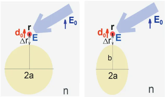
We use the well established approach to model fluorescence of a probe dipole (a molecule, a quantum dot, or an atom) located near a metal nanobody (a sphere or a spheroid) as is sketched in Figure 1. The calculation scheme and the relevant equation can be found in Ref. [14, 16]. There are three basic processes affecting luminescence intensity. First, incident local filed E enhancement depending on the specific point, r, the incident field wavelength λ and polarization, the metal type, the body shape and dimensions. The incident field enhancement well cor-relates with the extinction spectrum and changes with refractive index following the extinction changes. Second, radiative decay rate enhancement occurs which depends on an emitter position r, its dipole moment d0 orientation, emission wavelength λem, and generally correlates with the exctinction spectrum, i.e. it depends on the metal type and the body size and shape. Third, nonradiative decay rate also experiences enhancement in the presence of the nanobody depending on the distance to metal surface and correlating rather with the dielectric func-tion than with the extincfunc-tion, i.e. non-radiative decay does not follow directly extinction shift with size and shape.
Fig. 1: Displacement of an emitter and a nanobody used in calculations. Arrows indicate
orien-tation of an emitter dipole moment d0 and the incident radiation polarization, Δr is the distance between the metal nanobody surface and the emitter. See text for more detail.
The fluorescence enhancement factor develops as the product of local incident intensity enhancement (proportional to E2) and the quantum yield
defined by the radiative and nonradiative decay rates. For perfect emitters with the intrinsic quantum yield Q0 = 1, a metal body will necessarily promote quenching with Q(r) < Q0. However, for emitters with low Q0 < 1, quenching may not be pronounced and even Q(r) > Q0 can be obtained [16]. Generally, in simple colloidal metal structures with a few nm dielectric spacers (oxide shells, polyelectrolytes, Langmuir – Blodgett films) perfect emitters show enhancement up to 10 times whereas poor emitters show enhancement factors rising inversely proportional to Q0, i.e. 100 times enhancement becomes feasi-ble for Q0 < 0.1. Special arrangements of nanobodies, nanoantennas, and peri-odic structures enable higher enhancement provided an emitter is placed in the proper positions.
We shall consider here the metal spheres and spheroids which are appreci-ated in many works since these allow analytical calculations, with full account of size effect in scattering for spheres (Mie theory) and using the quasistatic model for spheroids (implying a nanobody is much smaller than λ). Spheroids are sup-posed to represent a reasonable approximation for nanorods [17]. Both types of particles can be obtained by means of colloidal chemistry without lithography, epitaxy and etching thus enabling chip and versatile bottom-up engineering meeting the general concept of colloidal photonics as an emerging technology platform [18]. The most favorable situations for fluorescence enhancement are shown in Figure 1. Since very large number of the above listed parameters is involved we shall fix most of them using the realistic and reasonable values and cases to illustrate the essence of the sensing conception.
The photoluminescence intensity enhancement factor FPL for a dipole emitter near a metal nanobody at point r can be calculated as a product of the incident excitation intensity enhancement G and emitter quantum yield modification
Q/Q0, where Q0 is the intrinsic quantum yield in vacuum,
0 2 rad 0 2 0 rad 0 nonrad 0 0 ( , ) ( , , ) ( , ) ( ) ( , ) ( , )/ ( ) . ( )[ ( , )/ ( ) ( , )/ ( ) 1] 1 ( , ) PL Q F G Q Q ω ω ω ω ω ω γ ω γ ω ω γ ω γ ω γ ω γ ω ω ′ = ′ ′ ′ ′ = + − + ′ ′ ′ ′ ′ r r r E r r r r E r (1)
Here E (E0) is electric field at the point of interest with (without) a metal body;
ω (ω′) is the excitation (emission) frequency; γrad (γnonrad) is radiative (nonradiative) decay rate of the emitter at the point of interest in presence of a metal nanobody; γ0 is its decay rate in vacuum; Q0 = γ0/(γ0 + γint) is the intrinsic quantum yield of the
emitter with γint being the intrinsic nonradiative decay rate (it does not depend on the nanobody). We consider that polarization of the incident radiation and the dipole moment orientation coincide which enables the maximal photolumines-cence enhancement. The enhancement factor depends on the distance between the metal nanobody surface and the emitter, Δr. More detail on the calculation scheme and explicit equations for the parametrs involved can be retrieved in Refs. [14, 16].
3 Results and discussion
3.1 Nanospheres
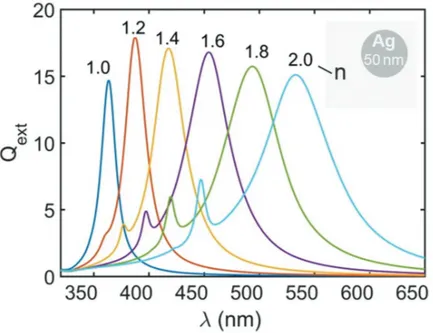
Figure 2 shows a set of the extinction spectra for Ag spheres to recall the primary shift of extinction spectra with familiar 200 nm/RIU sensitivity. The exctinc-tion spectrum also defines the spectral range where the expected fluorescence enhancement will occur. Ambient refractive index growth moves the extinc-tion spectrum and the radiative decay rate enhancement spectrum to longer wavelength and thus photoluminescence will be higher enhanced if originally extinction peak was in the short-wave range as compared to photoluminescence excitation and emission spectra. This approach is illustrated in Figure 3 where the photoluminescence enhancement factor FPL versus the ambient refractive
Fig. 2: Calculated dimensionless extinction spectra of silver spherical nanoparticles with
index is plotted for Ag spheres for various quantum yields in the absolute and in the normalized units. Here the figure of merit (FOM) is the refraction-dependent relative change in fluorescence intensity which is proportional to the relative change in the fluorescence enhancement factor FPL,
PL/ PL / FOM I I F F . n n ∆ ∆ ∆ ∆ = = (2)
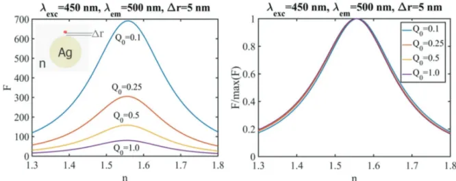
Both positive and negative slopes in the FPL(n) function can be used, i.e. for example, that the refractive index growth may give rise either to growth or to drop in photoluminescence intensity depending on the set of parameters chosen for an experimental implementation. One can see that the sensitiv-ity is feasible about 1000%/RIU for n close to 1.45 (positive slope) and 1.65 (negative slope). Implying 1% sensitivity in intensity measurements, one can arrive at the limit of detection (LOD) close to 0.001 RIU. Noteworthy, when comparing with the extinction peak based approach, monitoring of intensity may appear to be performed with cheaper equipment than monitoring spec-trum shape to evaluate its peak. Figure 3 (right panel) shows that sensitivity to refractive index does not actually depend on the absolute enhancement factors and on the intrinsic quantum yield. Though enhancement is higher for the lower quantum yield, its relative sensitivity to the refraction change remains the same. On should bear in mind that FOM changes across the n-axis so that for the target n range with the fixed emission and excitation wavelengths the optimal sphere diameter exists.
Fig. 3: Photoluminescence enhancement factors versus refractive index of the ambient medium
for the case of silver spherical nanoparticles (50 nm diameter) for various intrinsic quantum yield of the emitter Q0 with emission wavelength 500 nm and excitation wavelength 450 nm.
3.2 Nanorods
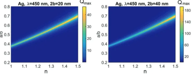
For spheroids extinction spectra and photoluminescence enhancement are rather narrow as compared to spheres and depend on both length and aspect ratio. Since the spectral range of photoluminescence enhancement correlates with the spectral position of the extinction band defined by the morphological resonance, we first evaluate the dependence of this band versus refractive index for various aspect ratio of a silver spheroid. In Figure 4 the peak exctinction is presented for various aspect ratio a/b values in the range of refractive index from 1 to 1.5 for the length 2b equal to 20 and 40 nm, and 450 nm wavelength (in a vacuum), respec-tively. The nanobody-emitter alignment corresponds to Figure 1 (right).
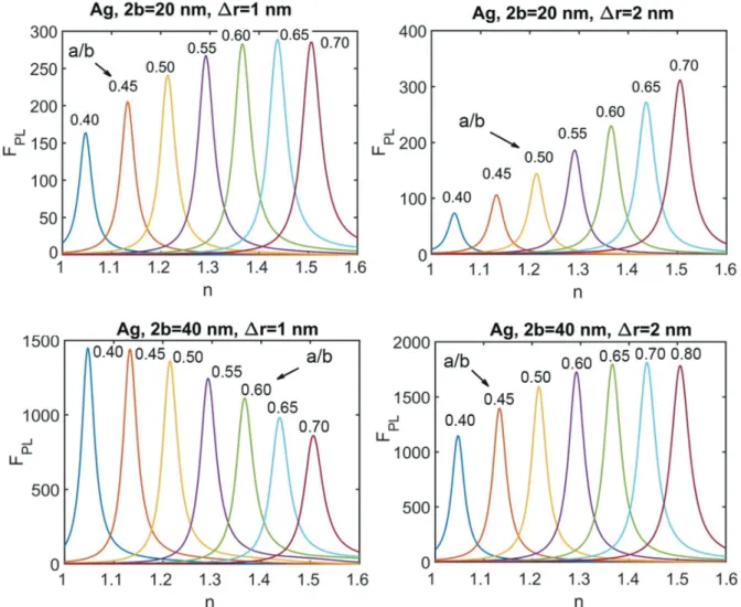
Results in Figure 4 indicate that for the parameters (the wavelength and the refractive index range) the most efficient enhancement occurs for the aspect ratio 0.4…0.7. Figure 5 shows the photoluminescence enhancement factor dependen-cies in detail for the emission wavelength 500 nm and excitation wavelength 450 nm. For every given aspect ratio enhancement change with refractive index is dependent on the refractive index value but the maximal sensitivity (the slope of the FPL(n) function) remains approximately the same. Thus a reasonable recipe will be to adjust aspect ratio (or possibly excitation and emission wavelengths) for the desirable n range. The figure of merit can reach 104%/RIU which means
that limit of detection will be down to Δn = 10−4 RIU supposing 1%
photolumines-cence intensity detectivity.
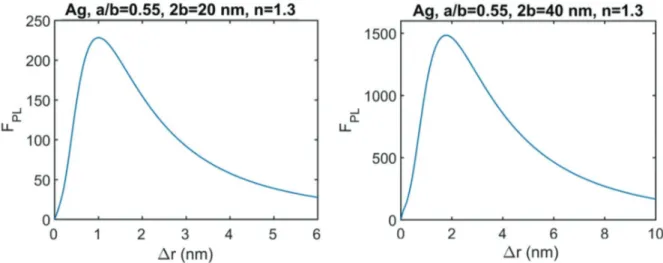
The maximal achievable slope of the FPL(n) function seems to be not very much sensitive to the spheroid length and the emitter-metal spacing Δr. However, in practical devices higher PL intensities may be appreciated to make detection easier in terms of signal-to-noise ratio, data acquisition time or detector grade.
Fig. 4: Calculated maximal dimensionless extinction of silver nanorods at the selected excitation
Therefore in Figure 6 we show sample calculations for FPL(Δr) for the two selected cases where the maximal FPL is reached at Δr = 1 nm for the spheroid length 20 nm and Δr = 2 nm for the spheroid length 40 nm.
3.3 Application issues
The results of calculations present the ideal cases under an assumption that the refractive index is the only ambient parameter affecting photoluminescence intensity. In this context, possible effects of other parameters should be taken into account and are briefly discussed here.
First, change in refractive index when being caused by the chemical content may affect photoluminescence intensity and spectrum because of
Fig. 5: Calculated photoluminescence enhancement factor for various aspect ratio for a silver
spheroid. Emission and excitation wavelengths are 500 and 450 nm (in vacuum), respectively. Spheroid length 2b = 20 nm (top) and 40 nm (bottom); an emitter metal spacing Δr = 1 nm (left) and 2 nm (right).
chemical effects, pH value and polarity. In this case, molecular fluorophores may appear to be not the best emitters for the proposed sensor applications. For every specific case of analysis, robustness of a given molecular probe should be checked. In this context, colloidal quantum dots, and especially core-shell quantum dot emitters with thick shells [19–21] may appear more robust and durable. Lanthanides or transition metal ions in nanocrystals [22, 23] may also become the advantageous probes. Refraction sensitive luminescent tips can be fabricated by means of colloidal crystals covered with noble metals [24] as well as by any other technique enabling cheap fabrication of nanostructured metal surface [25–27] with subsequent linkage of fluorescent probes via a dielectric spacer [28].
Second, an emitter – nanobody alignment presented in Figure 1 corresponds to the maximal enhancement of the photoluminescence intensity. In real situ-ations, random orientation of emitters and size dispersion in an ensemble of metal nanospheres will make enhancement somewhat lower [14], and the FOM value can be affected as well. However, owing to the symmetry of the problem the specific position of an emitter versus metal sphere will have no effect pro-vided that the emitter – metal distance is controlled (via spacer thickness). The situation is more complicated for the case of nanorods (spheroids) because for these nanobodies not only emitter orientation and distance to metal but also the specific position of an emitter is important. Therefore in the real situations the FOM numbers calculated may not be achieved and should be treated as reference values corresponding to the ideal and controllable alignment.
It is clear that colloidal nanoparticles can be adsorbed on glass or polymer sub-strates which can then serve as test strips. Fluorescent probes with nanoparticles
Fig. 6: Photoluminescence intensity enhancement factor versus emitter – metal spacing for the
two values of the spheroid length (20 nm and 40 nm) and refractive index n = 1.3. The emission wavelength is 500 nm, the excitation wavelength is 450 nm.
can be attached at the end of an optical fiber, and then local probing of refractive index can be performed using a fiber to guide both incident and emitted radia-tion. This “tip-enhanced refractometry” mode is most easy to be performed with fluorescence based plasmonic sensors rather than with extinction based ones.
4 Conclusions
A novel type of the refractive index sensor is proposed based on fluorescence intensity dependence in plasmonic nanostructures upon an ambient medium refractive index n value. The figure of merit (FOM) for this type of sensor is the relative photoluminescence intensity change per refractive index unit. For silver nanostructures in the range of typical liquids (n = 1.3…1.5) our calculations show FOM = 103%/RIU for spheres and 104%/RIU for spheroids which enable limit of
detection of Δn = 10−3 and 10−4 supposing the intensity detection accuracy of 1%.
These numbers correspond to the ideal cases of emitter – metal alignment and can be lower in real experiments. Core-shell colloidal quantum dots look promis-ing probes for this type of refractometry. Local probpromis-ing of refractive index changes in the tip-enhanced refractometry mode can be readily performed using a fiber for both excitation and detection of photoluminescence.
Acknowledgement: The work has been supported by BRFFR-TUBITAK #F16T/A-010
and TUBITAK no.115E679, and in part by Singapore National Research Founda-tion under NRF-NRFI2016-08.
References
1. D. Markov, D. Begari, D. J. Bornhop, Anal. Chem. 4 (2002) 5438.
2. S. V. Gaponenko, Introduction to Nanophotonics, Cambridge University Press, Cambridge UK (2010).
3. N. Jiang, X. Zhuo, J. Wang, Chem. Rev. (2017). DOI: 10.1021/acs.chemrev.7b00252 4. K. M. Mayer, J. Y. Hafner, Chem. Rev. 111 (2011) 3828.
5. K. A. Willets, R. P. Van Duyne, Annu. Rev. Phys. Chem. 58 (2007) 267. 6. Y. Sun, Y. Xia, Anal. Chem. 74 (2002) 5297.
7. F. Tam, C. Moran, N. Halas, J. Phys. Chem. B 108 (2004) 17290. 8. M. M. Miller, A. A. Lazarides, J. Phys. Chem. B 109 (2005) 21556. 9. H. Liao, C. L. Nehl, J. H. Hafner, Nanomedicine 1 (2006) 201.
10. J. Zhu, F. Zhang, J. Li, J. Zhao, Sens. Actuators, B: Chem. 183 (2013) 143. 11. P. K. Jain, M. A. El-Sayed, J. Phys. Chem. C 111 (2007) 17451.
13. C. D. Geddes (Ed.), Metal-Enhanced Fluorescence, John Wiley & Sons, Hoboken, New Jersey (2010).
14. D. V. Guzatov, S. V. Vaschenko, V. V. Stankevich, A. Ya. Lunevich, Y. F. Glukhov, S. V. Gaponenko, J. Phys. Chem. C 116 (2012) 10723.
15. Y. Chen, K. Munechika, D. S. Ginger, Nano Lett. 7 (2007) 690.
16. D. V. Guzatov, S. V. Gaponenko, H. V. Demir, AIP Adv. 8, (2018) 015324. 17. H. Chen, L. Shao, Q. Li, J. Wang, Chem. Soc. Rev. 42 (2013) 2679.
18. S. Gaponenko, H. V. Demir, C. Seassal, U. Woggon, Opt. Express 24 (2016) A430.
19. A. Eychmüller, J. Phys. Chem. B 104 (2000) 6514.
20. A. Eychmüller, A. L. Rogach, Pure Appl. Chem. 72 (2000) 179.
21. N. Gaponik, S. G. Hickey, D. Dorfs, A. L. Rogach, A. Eychmüller, Small 6 (2010) 1364.
22. J. T. Van Wijngaarden, M. M. Van Schooneveld, C. de Mello Donegá, A. Meijerink, Europhys. Lett. 93 (2011) 57005.
23. M. V. Artemyev, L. I. Gurinovich, A. P. Stupak, S. V. Gaponenko, Phys. Stat. Sol. (b) 224 (2001) 191.
24. S. V. Gaponenko, A. A. Gaiduk, O. S. Kulakovich, S. A. Maskevich, N. D. Strekal, O. A. Prokhorov, V. M. Shelekhina, J. Exper. Theor. Phys. Lett. 74 (2001) 309. 25. C. Zhu, D. Du, A. Eychmüller, Y. Lin, Chem. Rev. 115 (2015) 8896.
26. L. Lu, I. Randjelovic, R. Capek, N. Gaponik, J. Yang, H. Zhang, A. Eychmüller, Chem. Mater. 17 (2005) 5731.
27. V. Lesnyak, A. Wolf, A. Dubavik, L. Borchardt, S. V. Voitekhovich, N. Gaponik, S. Kaskel, A. Eychmüller, J. Amer. Chem. Soc. 133 (2011) 13413.
28. S. V. Vaschenko, A. A. Ramanenka, D. V. Guzatov, V. V. Stankevich, A. Y. Lunevich, Y. F. Glukhov, I. F. Sveklo, S. V. Gaponenko, J. Nanophotonics 6 (2012) 061710.