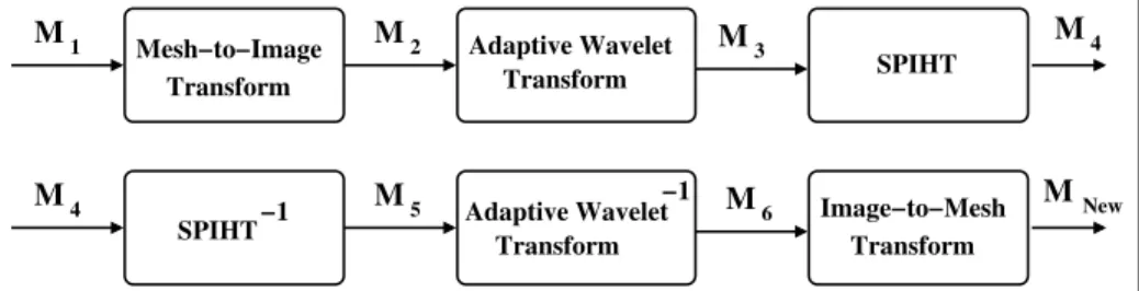
Connectivity-guided adaptive lifting transform for image like compression of meshes
Tam metin
Şekil
Benzer Belgeler
(Olve, Roy ve Wetter, 1999) DHK, işletmelerin sahip oldukları geçmiş verilere dayanan fiziksel (finansal) değerlerin yanında; geleceğe yönelik olarak müşteri
Bir aydan daha kýsa peri- yotlarda pseudonöbet gözlenen 9 hastanýn 5'i (%55.6) acil medikasyon dýþýnda tedavi almamakta, 4'ü (%44.4) ise psikiyatrik tedavi almaya devam etmek-
3 shows the maximum energy conversion efficiency and the optimum polarization rotation angle as functions of the input pump energy for the double-pass configuration.. Results of
yıl muntazaman (maden statistiği, madenle rimiz, madenlerimizin faaliyetleri diye arada bir adı değiştirilen) bir maden yıllığı çıkar tır. Yıllıkta imrarata
We take the developments in the use of instructional technology (instructional design, instructional media design, and process of the instructional design) into consideration
10B In early 2013 storyteller and virtual world resident Heidi Dahlsveen/Mimesis Monday curated a themed exhibit in the metaverse of Second Life ® by inviting three virtual artists
Consequently, beyond classical cardiovascular risk factors, a causative link between the epicardial adipose tissue and atrial fibrillation has also been suggested because of
Tablo 1’de yer alan analiz sonuçlarına göre araştırmaya katılan çalışanların duygusal tükenmişlik ile duyarsızlaşma düzeylerinin düşük düzeyde olduğu, kişisel
