Feasibility study1
Xiaoming Yang, MD, PhD PURPOSE: To develop a new method for monitoring balloon angio-
Bradley D. Bolster, Jr, MSE plasty by using an intravascular magnetic resonance (MR) imaging
Dara L. Kraitchman, VMD. technique.
PhD
Ergin Atalar, PhD MATERIALS AND METHODS: Nine New Zealand White rabbits
were used: seven for technique refinement, including surgery, de- vice insertion, stenosis creation, and MR protocol development; Index terms: Angioplasty, experimen- and two for the final MR imaging of the balloon angioplasty. The
Magnetic resonance (MR), intravas- in vivo experimental method involved insertion of a catheter an- cular tenna and a balloon catheter, via femoral arteriotomies bilaterally,
JVIR 1998; 9:953-959 into the target site of the upper abdominal aorta, where a stenosis
was artificially created by binding a plastic cable tie. Then, the en- Abbreviations: FOV = field of view, tire process of the dilation of the stenosis with balloon inflation RF = radiofrequency, SPGR = spoiled
gradient echo, TE = echo time, TR = rep- was monitored under MR fluoroscopy.
etition time, 3D = three-dimensional RESULTS: Catheter insertions were successful, and a 5-mm-long
stenosis of the aorta was produced in all nine rabbits. Eight com- plete balloon angioplasty procedures were satisfactorily monitored and recorded, showing clearly the stenosis of the aorta at the be- ginning of the procedure, the dilation of the stenosis during the balloon inflation, and the complete opening of the stenosis after balloon dilation.
CONCLUSION: Preliminary results of in vivo balloon angioplasty monitored with intravascular MR imaging are presented. MR fluo- roscopy, based on the intravascular MR imaging technique, may represent a potential alternative to x-ray fluoroscopy for guiding interventional treatment of cardiovascular diseases.
A new method of using magnetic nent advantages, such as excellent resonance (MR) imaging to guide contrast of soft tissues (including
'
the therapeutic procedures, called inter- vessel wall), ability to operate in (X.Y., D.L.K., E.A.) and Biomedical Engi-neering (B,D,B,), Johns Hopkins Univer- ventional MR imaging, is an excit- multiple image planes, no contrast sity school of Medicine, 601 N Caroline ing technological development. To agent needed, and no risk of ioniz- St, JHOC 4241, Baltimore, MD 21287- date, MR-guided therapies have ing radiation, MR-guided cardiovas- 0845; the Department of Clinical Radiol- been clinically limited to nonvascu-
ogy (X.Y.), Kuopio University Hospital, cular interventions are still in a de- ~ ~~ i ~ l ~ ~ d ; ~and the ~~~~~t~~~~ of ~ i ~ ,lar interventions, s.lch as discec- veloping phase. The reasons for this Electrical Engineering (E.A.), Bilkent tomy, laser ablation of breast can- limitation may include low signal- University, Ankara, Turkey. Received cer, laser or radio-frequency (RF) to-noise ratio, low frame rate, and February 2, 1998; revision requested ablation of head and neck tumors, the lack of an appropriate fast pulse March 10; revision received June 1; ac-
cepted June 2, This work was supported monitoring of prostate cancer ther- sequence. Since the application of by the M ~fellowship, c ~NIH ~G~~~~ ~ ~apy, interstitial cryotherapy, inter- fast gradient echo and echo planar
NO. R29HL57483, and the Whitaker stitial focused ultrasound surgery, pulse sequences, several investiga-
Foundation. Address correspondence and needle biopsies (1-4). Although tions of MR-guided vascular inter- to E.A.
MR imaging of the cardiovascular ventions have been reported re- o SCVIR, 1998 system has presented some promi- cently (5-9). These in vitro and in
954
Intravascular MR-monitored Balloon Angioplasty
November-December 1998 JVIR
vivo studies have focused primarily on either the evaluation of the MR compatibility of several vascular interventional devices, such as dif- ferent guide wires, catheters, bal- loon catheters, and stents, or the creation of MR tracking techniques for visualization and localization of these devices under MR imaging. To our knowledge, no in vivo stud- ies have been reported in which MR techniques are used to monitor the working process of vascular inter- ventions, such as balloon dilation of a stenotic vessel. This is likely due to the lack of an adequate animal model with vascular stenosis or oc- clusion, and the lack of a suitable MR imaging technique for directly monitoring and recording the entire process of the interventional proce- dure.
Recently, a catheter antenna, which can be inserted into a vessel for intravascular MR imaging, has been developed (10). Based on this development, one also can create MR fluoroscopy, which may be an alternative to x-ray fluoroscopy for vascular examinations and inter- ventions (11). The purpose of the present study was, by creating an animal model of aortic stenosis suit- able for in vivo investigations of MR-guided vascular interventions, to develop a new technique for mon- itoring balloon angioplasty under intravascular MR imaging, which is termed intravascular MR-monitored balloon angioplasty.
I
MATERIALS AND METHODSExperimental Design
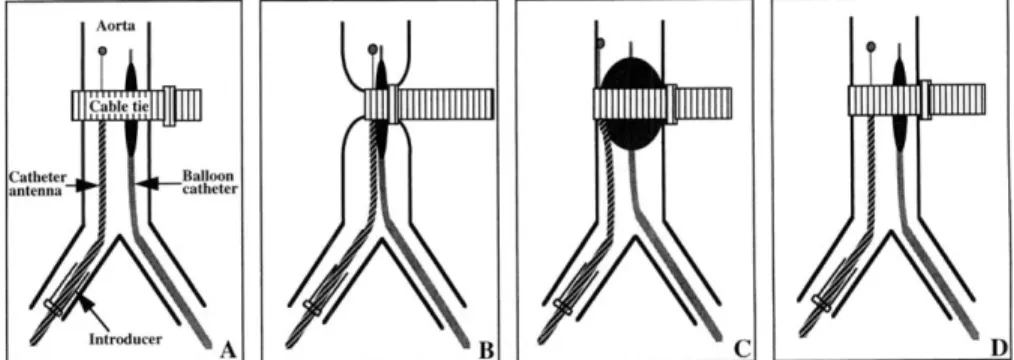
To develop the intravascular MR- monitored balloon angioplasty tech- nique in vivo, live rabbits were used in the present study. The proposed method involved insertion of a cath- eter antenna and a balloon cathe- ter, via femoral arteriotomies at both sides, into the target site of the upper abdominal aorta, where a stenosis was artificially created. Then, the entire process of dilation of the stenosis with balloon infla- tion was monitored and recorded under MR fluoroscopy (Fig 1).
Figure 1. Illustration of the experimental design for intravascular MR-monitored balloon angioplasty on a rabbit.
Catheter body Matching-tuning Extended inner conductor
I (thin coaxial cable) decoupling circuit
Connector to MR scanner Thick coaxial cable
Figure 2. Illustration of a preliminary design for the catheter antenna. The por- tion from the tip to the electronic circuitry is inserted into blood vessels.
Devices
Catheter antenna-The loopless catheter antenna has been previ- ously described elsewhere (10). Briefly, the catheter antenna sys- tem consists of a 5-cm-long conduct- ing wire that was an extended in- ner conductor from a 35-cm-long coaxial cable (the catheter body). The latter was connected to a matching tuningldecoupling circuit
(Fig 2). The conducting wire was 0.5 mm (1.5 F) and the coaxial cable was 1.0 mm (3.0 F) in diameter
(Fig 3). The principle of this design is very similar to the dipole an- tenna used in communications. Since this design has a very simple structure, it is relatively easy to
construct in very small diameters. The loopless catheter antenna can be used as a transmitlreceive probe for transmitting RF pulses and re- ceiving MR signal, or it can be used as a receive-only probe for MR sig- nal. In the receive-only mode, the RF pulses are transmitted from a n external coil such as a body coil.
Balloon catheter-A 4-F, 90-cm- long balloon catheter was used (Medi-tech/Boston Scientific, Water- town, MA). The balloon portion was 4 cm in length and 6 mm in diame- ter with a burst pressure of 15 atm, and contained two alloy (Tantalum) rings a t both proximal and distal ends of the balloon (Fig 3). The in- sertion of the balloon catheter into
velopment by testing different pulse sequences; and two for the final MR
--
j imaging of the balloon angioplasty
I procedures based on the previous
seven rabbit studies. The animals
: were treated according to the "Prin-
1
' ciples of Laboratory Animal Care" of the National Society for Medical Research and the "Guide for the Figure 3. The tip of the catheter an- Care and Usetenna (upper) and the tip of the balloon mals" (NIH Publication No. 80-23,
catheter (lower). revised 1985). The experimental
protocol was approved by the Ani- mal Studv Committee at our insti- the vessel was guided by a 0.018-
inch (0.4-mm) guide wire (Medi- tech/Boston Scientific), which was removed during MR imaging. The balloon catheter was tested with MR imaging and proved to be MR- compatible without producing sig- nificant artifacts, despite the two alloy rings on the balloon portion that were designed as markers for positioning the catheter under x-ray fluoroscopy.
Cable tie-To create an artificial stenosis, a 12-cm-long and 2.5-mm- wide plastic (polyethylene) cable tie (Baynesville Electronics, Baltimore, MD) was bound around the exposed upper abdominal aorta of the rabbit
(Fig 1). The cable tie was tightened
in a direction opposite the usual direction so that the cable tie slid open easily as the balloon inflated. The ability to create the stenosis with the cable tie and to release the cable tie tightness with balloon in- flation was repeatedly confirmed by testing it on a phantom (6 mm in inner diameter) before the animal experiments. The cable tie also proved to be MR-compatible.
Surgical Procedure on Rabbits
To adapt this new technique for further use in small arteries on hu- mans, nine female New Zealand White rabbits, 3.5-4.5 kg in weight, were used in the present study: seven for technical refinement, in- cluding surgery, the insertion of the catheter antenna and the balloon catheter, the creation of the artifi- cial stenosis and its dilation by bal- loon inflation, and MR protocol de-
tution.
The rabbit was first anesthetized with a mixture of ketamine (35 mgl kg) and acepromazine (0.75 mgkg) as well as atropine (0.5 mgkg) ad- ministered intramuscularly. Pento- barbital (25 mgkg, intravenously) was later administered to bring the animal to a surgical plane of anes- thesia. Femoral arteries at both sides were dissected free and can- nulated, one with the catheter an- tenna for intravascular MR imaging and the other with the balloon cath- eter for intravascular stenotic dila- tion. To create an artificial stenosis a t the upper abdominal aorta of the rabbit, the following surgical steps were performed: (a) the upper ab- dominal wall was anteriorly opened along the midline, allowing expo- sure of the abdominal cavity; ( b ) the upper abdominal organs were gently shifted from the abdominal cavity onto the right outside the rabbit's body, allowing exposure of the posterior parietal peritoneum;
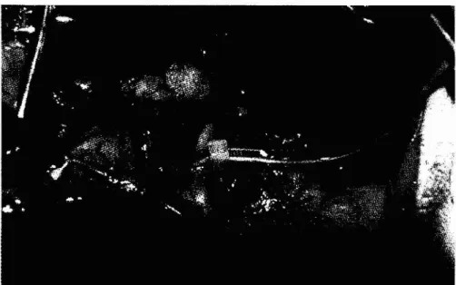
(c) a 1.5-cm long section of the up- per abdominal aorta, at a level 1.5 cm above the origin of the left renal artery, was carefully exposed; and . - ( d ) the plastic cable tie was bound around the exposed aortic portion to create the artificial stenosis (Fig 4).
A 4-F introducer sheath (Medi- tech/Boston Scientific) was inserted via the right femoral artery into the right iliac artery, and then the catheter antenna was sent through the introducer up to the aortic level where the cable tie was placed. The balloon catheter was directly in- serted via the left femoral artery into the upper abdominal aorta and positioned side by side along with the catheter antenna. The actual
position of the tips of both the cath- eter antenna and the balloon cathe- ter was determined by measuring the distance between the cable tie site and the puncture point of the femoral artery, and by manually feeling both antenna and balloon through the exposed aortic section. The central point of the balloon and the most sensitive region of the loopless catheter antenna (ie, the point between the extended inner conductor and the catheter body) were centered iust at the level of the cable tie
see.
Subsequently, the rabbit was transferred to the MR imaging facil- ity, while anesthesia was main- tained with serial infusions of pen- tobarbital (20 mgkglh, intrave- nously) approximately every 30 minutes, or as needed. Non-ferro- magnetic electrodes were attached to the rabbit limbs for measurement of the surface electrocardiogram (ECG). The aortic stenosis was im- aged using an ECG-gated MR tech- nique. On completion of the experi- ments, the animals were killed with a dose of 100 mLkg of pentobarbi- tal.
Intravascular MR Imaging Technique
All experiments were performed on a Signa 1.5-T imager (GE Med- ical Systems, Milwaukee, WI). The rabbit was placed in a supine posi- tion in the imager and aligned with the main magnetic field. A coronal scout image was first ob- tained with use of a body coil to determine the anatomic position of the abdominal aorta with the fol- lowing imaging parameters: fast spoiled gradient-echo (SPGR) pulse sequence, repetition time (TR) mseclecho time (TE) msec =
6.311.5, 31.3-kHz bandwidth, 32-cm field of view (FOV), 256 x 160 matrix, and 10-mm slice thickness. Then, axial images of the target aorta were obtained with the loopless catheter antenna in the receive-only mode. The im- aging parameters were fast SPGR pulse sequence, TRITE = 13.314.4, 8-cm FOV, 256 X 256 matrix, 20" flip angle, and 3-mm slice thick-
956
Intravascular MR-monitored Balloon Angioplasty
November-December 1998 JVIR
ness. Image intensity was cor- rected by using the image inten- sity correction algorithm described elsewhere (10). Before balloon di- lation, the mode of operation of the catheter antenna was changed from receive-only to transmitlre- ceive. For recording the entire pro- cess of intravascular MR-moni- tored balloon dilation, we used a fast SPGR pulse sequence with TRITE = 9.912.5, 18 x 1.7-cm
FOV, 256 x 24 matrix, and a 5-mm slice thickness. Using this sequence, we recorded the entire process of balloon angioplasty a t a rate of 4.2 frames per second. By performing contrast-enhanced three-dimensional (3D) MR aortog- r a ~ h i e s with an intravenous iniec-
tiin of 3 mL of Omniscan (287 "mg Figure 4. Surgery on a rabbit. The cable tie is bound around the exposed portion of gadodiamide per milliliter) (Ny- of the upper abdominal aorta.
corned, Princeton, NJ), we also compared the aortic changes be- fore-and after balloon angioplasty, using the following parameters: 3D fast SPGR pulse sequence, TRITE = 8.611.6, 32-kHz band- width, 20-cm FOV, 256 x 128 ma- trix, 45" flip angle, and 1-mm slice thickness.
Balloon Angioplasty Procedure
The balloon was inflated by man- ual injection of 2 mL of contrast medium with a 20-mL plastic sy- ringe. The contrast medium used for balloon inflation was 3% Magne-
vist (Berlex Laboratories, Wayne, NJ) diluted with saline (14 mg of gadolinium per milliliter). The bal- loon inflation was started 5-7 sec- onds after beginning MR imaging, maintained by manual control for 10 seconds, and terminated 5-7 sec- onds before the completion of MR imaging. The total MR imaging time was 24 seconds for each bal- loon angioplasty procedure. Five to six procedures of balloon dilation of the cable-tightened aortic stenosis were carried out for each of the seven protocol development rabbits, and four balloon angioplasty proce- dures were performed in each of the final MR-imaged rabbits.
I
RESULTS
The techniques of both catheter insertion and stenosis creation were successfully performed in all nine rabbits. An approximately 5-mm-long artificial stenosis of the rabbit aorta was produced by tightening the cable tie. The ste- nosis was efficiently dilated dur- ing the balloon inflation and al- most completely opened to its orig- inal shape after balloon interven- tion, which enabled repeat proce- dures of balloon dilation in each rabbit. The contrast medium in- jected into the balloon produced high-signal images, which pro- vided an excellent outline of the aortic stenosis and contrasted well to the non-signal aortic wall.
On axial intravascular MR im- ages, the lumen of the abdominal aorta was clearly seen as a bright circle signal, in which both the catheter antenna and the empty balloon were represented as signal voids (Fig 5). The catheter antenna
was surrounded by very high signal because of its high sensitivity to the nearby objects. On coronal images, the two alloy rings of the balloon were demonstrated as two small non-signal circles (image artifacts). In our protocol, we used the two
Figure 5. Axial MR image of the rab- bit aorta. The aorta presents a s a bright signal circle, which includes a catheter antenna (short arrow) and a deflated balloon (long arrow) both without sig- nal. Imaging parameters: fast SPGR, TFUTE = 13.314.4, 8-cm FOV, 256 X 256 matrix, 20" flip angle, and 3-mm slice thickness.
alloy markers to precisely adjust the position of the balloon during MR imaging. The artificially in- duced aortic stenosis was clearly observed at the level between the two alloy markers of the balloon
(Fig 6).
Entire balloon angioplasty proce- dures were satisfactorily monitored and recorded under MR fluoroscopy, presenting clearly the aortic steno-
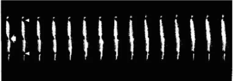
Figure 6. A serial frame from the MR fluoroscopy record of intravascular MR- monitored balloon angioplasty, showing the aortic stenosis (arrow) a t the beginning of the procedure and complete opening of the stenosis after total balloon inflation. Arrowheads indicate the circle image artifacts produced by the two alloy rings of the balloon portion. Imaging parameters: fast SPGR, TRPTE = 9.912.5, 18 x 1.7-cm FOV, 256 X 24 matrix, 5-mm slice thickness, and 4.2 frames per second.
Figure 7. Contrast-enhanced 3D MR aortography of the rabbit. Comparison of images obtained before and after bal- loon dilation of the stenotic aorta. The artificial stenosis (thick arrows) with decreased distal blood flow (arrowhead) is clearly seen before the balloon angio- plasty (a) and is opened with increased distal blood flow after angioplasty (b). On these two images, the balloon por- tion is withdrawn from the stenotic aorta. Imaging parameters: 3D fast SPGR pulse sequence, TRPTE = 8.611.6, 32-kHz bandwidth, 20-cm FOV, 256 x
128 matrix, 45" flip angle, and 1-mm slice thickness.
sis a t the beginning of the proce- dure, the dilation of the stenosis during balloon inflation, and the complete opening of the stenosis after balloon dilation. Figure 6
shows images obtained from MR fluoroscopy, recorded during the in- travascular MR-monitored balloon angioplasty process. The aortic ste- nosis with decreased distal blood flow was also clearly observed and was opened with immediately in- creased distal blood flow after the balloon angioplasty (Fig 7).
thkrefore cannot be used for the purpose of interventional therapies. In addition, with MR angiography, one can satisfactorily observe the changes within the vascular lumen, such a s a stenosis or occlusion, but not changes in the vessel wall. In- travascular sonography can provide a cross-sectional view of vessels, which is particularly useful in the demonstration of calcified plaque in the vessel wall and percent stenosis of the vessel lumen (15,16). Re- cently, a few studies have demon- strated the useful applications of intravascular sonography for guid- ing fenestration in aortic dissection (17) and also for guiding endovascu- lar stent graft placement (18).
To improve the signal-to-noise ratio, some investigators have used intravascular receiver probes to ob- tain high-resolution MR images of the vessels (19-23). Recently, a new approach to intravascular MR imag- ing, which is performed by inserting a catheter coil or a loopless catheter antenna into blood vessels, has been developed (10,24). It has been demonstrated experimentally that this new approach will have many
applications for vascular examina- tions, including the following: ( a ) localizing atherosclerotic plaques on the arterial wall, measuring the thickness of the plaques, and ana- lyzing the components of atheroscle- rotic plaques (25); (6) obtaining high-resolution MR images of ves- sels with a high signal-to-noise ra- tio that cannot be achieved with standard receiver coils (10); ( c ) ob- serving the cross-sectional images of stenotic arteries. which cannot be seen on standard angiography im- ages (24); and ( d ) creating intravas- cular MR fluoroscopy, which may function a s a n alternative to x-ray fluoroscopy for vascular examina- tions and interventions (11). In the present study, by using the intra- vascular catheter antenna, we have demonstrated the successful initial results of in vivo intravascular MR- monitored balloon angioplasty. These confirm that the intravascu- lar catheter antenna is useful for the creation of MR fluoroscopy and also provides the ability to perform vascular interventional techniques under MR imaging guidance.
The rabbit model of artificial aor- tic stenosis in the present study is a promising model to investigate in- travascular MR imaging, intravas- cular MR-guided balloon angio- plasty, and, theoretically, for future investigations of other intravascular MR-guided vascular interventions, such a s intravascular MR-guided stent placement. The Magnevist a t
3% concentration worked very well
for both balloon inflation and obser- vation under MR fluoroscopy. The two alloy rings of the balloon por- tion served a s excellent markers for accurately positioning the balloon under MR fluoroscopy, similar to x-ray fluoroscopy. These markers are very useful for any interven- tional MR procedure.
The technique presented herein requires further modification, im- provement, and practice. Although we currently face some technical construction challenges, a thinner catheter antenna would be better for intravascular MR-guided balloon angioplasty. Similar to a guide wire, the thin catheter antenna can be directly inserted into the central
958
Intravascular MR-monitored Balloon Angioplasty
November-December 1998 JVIRchannel of a balloon catheter, which should also theoretically enable its use in an endovascular stent deliv- ery system. This central positioning of the catheter antenna will also improve image quality because the centrally placed catheter antenna will result in a more equally distrib- uted magnetic signal field within the vessel lumen than a n eccen- tricly positioned one. Meanwhile, a centrally positioned catheter an- tenna within an interventional catheter will avoid the requirement of a second vascular access site and the need to pass two catheters through a stenosis, which increases the risk of failure and of complica- tions such as dissection of the ves- sel wall. The current method of side-by-side positioning of the cath- eter antenna and the balloon cathe- ter may be applied to recanalize a totally occluded artery. For exam- ple, the catheter antenna may be positioned in a venous vessel that is parallel to the target artery, provid- ing an image of a vein and an ar- tery side by side. Thus, the recana- lization of the arterial occlusion with use of some interventional techniques also can be monitored with MR fluoroscopy if a corre- sponding MR imaging protocol can be established.
The intravascular MR-guided in- terventions may be best performed under a short MR imager or an open MR system, which allows the head and lower extremities of the patient to be exposed outside the imager, while clinicians can easily communicate with and conveniently monitor the patient at any time during the interventional procedure. In addition, in the present study we monitored the balloon angioplasty process by using MR fluoroscopy at 4.2 frames per second. It is possible to increase this rate with the opti- mization of the pulse sequence. We expect that with proper modifica- tion of the pulse sequence we will operate MR fluoroscopy at a frame rate higher than 10 frames per sec- ond.
Recently, some research groups have reported the results of in vivo studies on the development of MR catheter tracking techniques. In two
research groups, investigators tested different MR-compatible catheters, such as the balloon cath- eter, the embolization catheter, and the angiographic catheter, which were equipped with either a RF coil incorporated into the catheter tip or a copper wire configured around the entire catheter for placement guid- ance or for visualizing the position of these interventionally used cathe- ters (5,7). In our research group, using the loopless catheter antenna, we developed a narrow catheter- tracking FOV imaging technique, which enabled us to track an intra- vascular catheter under MR fluoros- copy (11). The combination of MR catheter tracking techniques with the intravascular MR-monitoring technique will certainly refine the concept of MR-guided vascular in- terventional therapies, and provide the groundwork for use in clinical practice in the near future.
Functional MR before and after therapeutic interventions is a cur- rent reality, and the idea of on-line monitoring of the effectiveness of
-
such interventions as a guide to the next therapeutic step is very attrac- tive. Functional cardiac MR tech- niques, such as MR myocardial tag- ging (26,27), perfusion (28,291, and blood oxygen level dependent (BOLD) imaging techniques (30,311, have opened up new avenues in the investigation of ischemic heart dis- eases. Combined with functional cardiac MR techniques, the results of our intravascular MR-guided bal- loon angioplasty represent the po- tential for on-line management of ischemic heart disease in the fu- ture, although great effort is re- quired to develop MR-guided coro- nary interventions.In conclusion, we demonstrate the preliminary result of in vivo in- travascular MR-monitored balloon angioplasty. This success confirms that the intravascular catheter an- tenna has provided the potential for creation of MR fluoroscopy, which may represent an alternative to x- ray fluoroscopy for guiding inter- ventional t h e r a ~ i e s of cardiovascu- lar diseases.
Acknowledgments: The authors thank Mary McAllister for her help in manuscript preparation, and Walter Rogers, Ogan Ocali, Keven Phelan, and Rick Shunk for providing catheters. Special thanks to Dr. James Earls for his help in 3D contrast-enhanced MR angiography studies.
1
WEBSITEThe entire record of the intravas- cular MR-monitored balloon angio- plasty procedure can be accessed on our web-page on the internet (http:l/ www.mri.jhu.edu/IVMRI/balloon).
References
1. Lufkin RB. Interventional MR im- aging. Radiology 1995; 197:16-18. 2. Jolesz FA, Blumenfeld SM. Inter-
ventional use of magnetic resonance imaging. Magn Reson Quarterly
1994; 10:85-96.
3. Silverman SG, Collick BD, Figueira MR, Khorasani R, Adams DF, New- man RW, et al. Interactive MR- guided biopsy in a n open-configura- tion MR imaging system. Radiology 1995; 197:175-181.
4. Hagspiel KD, Kandarpa K, Jolesz FA. Interventional MR imaging. JVIR 1997; 8:745-758.
5. Glowinski A, Adam G, Bucker A, Neuerburg J , van Vaals J J , Gunther RW. Catheter visualization using locally induced, actively controlled field inhomogeneities. Magn Reson Med 1997; 38:253-258.
6. Kochli VD, McKinnon GC, Hofmann E, von Schulthess GK. Vascular interventions guided by ultrafast MR imaging: evaluation of different materials. Magn Reson Med 1994; 31:309-314.
7. Wildermuth S, Debatin J F , Leung DA, e t al. MR imaging-guided in- travascular procedures: initial dem- onstration in a pig model. Radiology
1997; 202:578-583.
8. Bakker CJ, Hoogeveen RM, Hurtak
WF, van Vaals J J , Viergever MA, Mali WP. MR-guided endovascular interventions: susceptibility-based catheter and near-real-time imaging technique. Radiology 1997; 202:273- 276.
9. Stroman PW, Roby P, Alikacem N, et al. Will it be feasible to insert endoprostheses under interventional MRI? J Endovasc Surg 1996; 3:396- 404.
10. Ocali 0, Atalar E. Intravascular magnetic resonance imaging using a
loopless catheter antenna. Magn Re- son Med 1997; 37:112-118.
11. Atalar E, Kraitchman DL, Lesho J , et al. Catheter-tracking FOV MR fluoroscopy. Magn Reson Med 1998 (accepted).
12. Edelman RR, Manning WJ, Bur- stein D, Paulin S. Coronary arter- ies: breath-hold MR angiography. Radiology 1991; 181:641-643. 13. Duerinckx AJ, Atkinson DP, Mint-
orovitch J, Simonetti OP, Vrman MK. Two-dimensional coronary MRA: limitations and artifacts. Eur Radiol 1996; 6:312-325.
14. Davis CP, Schopke WD, Seifert B, Schneider E, Pfammatter T, Deba- tin JF. MR angiography of pa- tients with peripheral arterial dis- ease before and after transluminal angioplasty. AJR 1997; 168:1027- 1034.
15. Finet G, Maurincomme E, Tabib A, e t al. Artifacts in intravascular ultrasound imaging: analyses and implications. Ultrasound Med Biol 1993; 19:533-547.
16. Link TM, Kerber S, Poppelmann M, et al. In vitro correlation of intra- vascular ultrasound and direct mag- nification radiography for calcified arterial lesions. Invest Radiol 1994; 29:420-426.
17. Williams DM, Lee DY, Hamilton BH, et al. Dissected aorta: percu- taneous treatment of ischemic com-
plications-principles and results. JVIR 1997; 8:605-625.
18. Beebe HG. Imaging modalities for aortic endografting. J Endovasc Surg 1997; 4:111-123.
19. Kantor HL, Briggs RW, Balaban RS. In vivo 31p nuclear magnetic resonance measurements in canine heart using a catheter-coil. Circ Res 1984; 55:261-266.
20. Hurst GC, Hua J , Duerk JL, Cohen
AM. Intravascular (catheter) NMR receiver probe: preliminary design analysis and application to canine iliofemoral imaging. Magn Reson Med 1992; 24:343-357.
21. Kandarpa K, Jakab P, Patz S, Schoen FJ, Jolesz FA. Prototype miniature endoluminal MR imaging catheter. JVIR 1993; 4:419-427. 22. Martin AJ, Henkelman RM. Intra-
vascular MR imaging in a porcine animal model. Magn Reson Med 1994; 32:224-229.
23. McDonald GG, Chwialkowski M, Peshock RM. Performance compar- ison of several coil geometries for use in catheters. Radiology 1993; 189:319.
24. Atalar E, Bottomley PA, Ocali 0 , et al. High resolution intravascular MRI and MRS by using a catheter receiver coil. Magn Reson Med 1996; 36:596-605.
25. Correia LCL, Atalar E, Kelemen MD, et al. Intravascular magnetic
resonance imaging of aortic athero- sclerotic plaque composition. Arte- rioscler Thromb Vasc Biol 1997; 17: 3626-3632.
26. Zerhouni EA, Parish DM, Rogers WJ, Yang A, Shapiro EP. Human heart: tagging with MR imaging-a method for noninvasive assessment of myocardial motion. Radiology 1988; 169:59-63.
27. Axel L, Dougherty L. MR imaging of motion with spatial modulation of magnetization. Radiology 1989; 171: 841-845.
28. Higgins CB, Sakuma H. Heart dis- ease: functional evaluation with MR imaging. Radiology 1996; 199:307- 315.
29. Schwitter J , Sakuma H, Saeed M, Wendland MF, Higgins CB. Very fast cardiac imaging. Magn Reson Imaging Clin North Am 1996; 4:419-432.
30. Atalay MK, Forder JR, Chacko VP, Kawamoto S, Zerhouni EA. Oxy- genation in the rabbit myocardium: assessment with susceptibility-de- pendent MR imaging. Radiology 1993; 189:759-764.
31. Niemi P, Poncelet BP, Kwong KK,
et al. Myocardial intensity changes associated with flow stimulation in blood oxygenation sensitive mag- netic resonance imaging. Magn Re- son Med 1996; 36:78-82.