An assembly line design and construction
for a small manufacturing company
Ramazan Yaman
Department of Industrial Engineering, Faculty of Engineering and Architecture, Balikesir University, Balikesir, Turkey
Abstract
Purpose – This study seeks to present a simple assembly line design and its balance for a low-volume manufacturing company.
Design/methodology/approach – The study presents experiences with the design and implementation of a simple assembly line. The implementation concerns three aspects; design and construction of the assembly line, the assembly analysis of the product, and then balancing of the line. It also discusses construction and implementation difficulties of this tactical tool in the case company.
Findings – The study presents some outcomes from the design, implementation, and balancing of an assembly line for SMEs. Research limitations/implications – The study is limited by the case company and its experience.
Practical implications – This study is not pure theoretical study, it has application stages for industry, and it provides some real interface for the people from SMEs.
Originality/value – The approach has an original value in respect of implementation of assembly line for a small manufacturing company which has many limitations.
Keywords Small to medium-sized enterprises, Assembly, Design Paper type Research paper
1. Introduction
The importance of the SME’s for any nation is well known (Imrek, 2002; Kosgeb, 2007). They provide balanced employment, economical values, reputation, technology, and social advantages, which are crucial for nations and the world. Well-established companies have gained many competitive advantages as a result of proper implementation of system automation. These advantages include cost reductions, quality improvements on products and services, as well as effective use of their resources. These advantages have increased the gap existing between such well-managed companies and SME’s that need to embrace timely management strategies.
In winds of change, SME’s have to find and adopt tactical tools that have been effectively used among well-established companies. Well-established companies that manufacture in significant volume have effectively used advantages of assembly lines within their production strategy. For SME’s to be competitive, part of their manufacturing strategy needs to focus on the effective use of assembly lines as a means of cost reduction while underpinning product quality.
This study comprises five subsections. The first subsection is an introduction to SMEs and their main problems, together
with assembly line basics. Section 2 deals with assembly lines in small manufacturing companies. The case study company and its assembly line solution are in Section 3, conclusions are drawn in Section 4 and Section 5 presents a discussion and recommendations for future works.
1.1 Basic motivation about SMEs
Small- and medium-size manufacturing companies are important for economies (Imrek, 2002; Kosgeb, 2007). Their capabilities give direction for change, influencing the economies of nations. The SMEs are mostly established by individual entrepreneurs (Lamping and Kuehl, 1997). Frequently, however, the entrepreneur may have a limited experience, abilities, knowledge, etc. to make decisions regarding management, marketing, finance, technical, strategic situations in order to survive the competition with well-established companies in the global economy (Yaman et al., 2003). To become viable in the supply chain and survive with well-established companies, SME’s are required to improve speed, efficiency, and quality of their operations with limited resources available to them (Wilton and Reavill, 1997). SME’s most common problems may be grouped in five categories; financial, management, technological, and human resources. More details on the problems faced by SME’s can be gathered from Raymond et al. (1996), Peel and
The current issue and full text archive of this journal is available at www.emeraldinsight.com/0144-5154.htm
Assembly Automation 28/2 (2008) 163 – 172
q Emerald Group Publishing Limited [ISSN 0144-5154]
[DOI 10.1108/01445150810863743]
The author wishes to acknowledge all the staff of the CIKA Bike Company, Mr Ayhan Kaynak (the Entrepreneur), and Mr Nuri Sipahi (Technical manager) for their cooperation in analysis, discussion, construction, and implementation. He also wishes to thank constructive comments of the reviewers and Professor D.T. Gethin from University College of Swansea.
Bridge (1998), Hu and Schive (1998), Imrek (2002) and Yaman et al. (2003).
The SME’s have many advantages for the national and international economies. First of all, they have high flexibility to cope with changes and to respond to demand and demand changes. Cumulatively, they also provide an important percentage of employment and capture an important market share. They provide stability and a balance for economy and social change. With these advantages, SME’s are set to exit into the future.
1.2 Basic motivation about assembly lines
Flow lines, of which, assembly lines are an example is the most commonly used system in a mass production environment. Assembly lines enable the assembly of complex products by
workers who have received a short training period
(Gunasekaran and Cecile, 1998). Thus, an efficient assembly line design as part of a manufacturing system is a vital problem for some companies. An assembly line is a usual solution for medium and high-production volumes.
The main objective of an assembly line is to increase the efficiency of the system by maximizing the ratio between throughput and required cost. An assembly chart shows the sequence of operations required to put a product together as the final stage of manufacture. The assembly process can be shown graphically by using the parts list and related drawings. In complex products, the sequence of assembly may have alternatives. For a good decision among these alternatives, time standards and a precedence list are required (Meyers and Stephens, 2005; Boysen et al., 2007). With this background an assembly line may be designed and balanced with the aim of optimizing the assembly system.
In this study, the full process can be summarized as; when all parts produced in manufacturing or received from suppliers and available for assembly, then proceed to produce subassemblies, followed by final assembly. This is followed by any functional checks and then packing for distribution. 1.3 A simple assembly line in a small manufacturing company
This study has focused on a small-size manufacturing company’s final assembly capacity. The company wants to improve and increase its production capacity, quality, and net profit. According to their experience, they do not have any bottleneck on the production and procurement part of the manufacturing. They are having problems in the assembly of their products. For this reason, they have decided to explore a number of scenarios to solve their assembly problem. This problem could be solved by an assembly line approach, and this solution may also improve most of the outcomes for the business. They also stipulate the following limitations:
. the solution must not require high investment and
technology;
. the solution must provide high flexibility to assemble
different product types;
. the solution must not require highly skill workers (they
should be trained in a few working days); and
. the capacity of the final assembly line solution must be
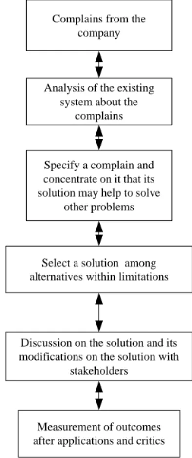
wide, ranging from tens to hundreds of products per day. There is no absolute standard method to improve productivity in the manual assembly system that may be implemented by any SME. However, Figure 1 shows a possible structured
solution approach to solve this problem. This approach has been applied in the case study company and relevant details are set out in the following sections.
This structured approach can be explained as follows; box 1 is for complaints, box 2 represents analysis of complaints for the existing system, box 3 identifies a complaint and focuses on its solution, box 4 is for alternatives considering limitations, box 5 discusses the solution and modifications with stakeholders, box 6 is for measurement of outcomes. 1.4 The case study company
The case study company was established in 1978 by an entrepreneur for manufacturing bicycle pumps. The original
company had a 50 m2job shop. The company then started to
manufacture forks and frames for different sizes and types of bicycles in 1980 and it also started assembly of these products. In 1999, the company designed and started produces some parts for tri-cycles for seniors and assembled them for the local market with a very limited market volume (around 350 tri-cycles per year). In 2005, design improvements were undertaken, leading to export opportunities. Now, the company aims to reach an important capacity for this product (more than 3,000 tri-cycles per year). Achieving this volume sets new business challenges in order to manage cost and ensure product quality.
Currently the company has two sections that occupy
250 m2each. One is used for manufacturing some parts (and
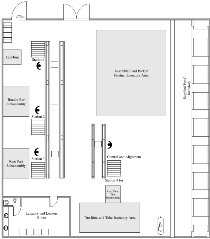
spare parts); the other is used for inventory and assembly. The layout is shown schematically in Figures 2 and 3.
Figure 1 A Structured approach to solve some problems of the SMEs
Complains from the company
Specify a complain and concentrate on it that its solution may help to solve
other problems
Select a solution among alternatives within limitations
Discussion on the solution and its modifications on the solution with
stakeholders
Measurement of outcomes after applications and critics
Analysis of the existing system about the
This existing manufacturing workshop layout has been completed using the experience of the entrepreneur. Basically, the shaping section has lathes, saw, and different capacity presses. In this section, the company constructs shaping fixtures and it produces parts that require material removal, forming, and bending processes. Where required, parts are welded and painted in this manufacturing section.
Prior to the installation of an assembly line, the company assembled product on the workbenches and floor in
non-ergonomic conditions that are again based on the
entrepreneurs’ and workers’ experience. This layout is shown in Figure 3. This untidy work environment has caused many problems, such as poor work performance, uncompleted final products (high volumes of work in progress), insufficient floor space, and poor inventory management. It is believed that these problems may be addressed through application of a sound assembly strategy. 1.4.1 About the product
The company manufactures different sizes and types of bicycles for transport, sport, and leisure. As explained in the previous paragraphs, the company has also started to manufacture tri-cycles for seniors for the local and
global market. Some photographs showing this product and its sub assemblies can be seen in following Figures 4-9.
The product market experiences strong seasonal effects and the seasonal changes affect company income and many other production factors such as inventory, workforce level.
2. Case study company problems, limitations, and
its assembly line solution
The entrepreneur has received complaints from his
management staff about production capacity of the tri-cycles. A critical analysis has been carried out by the author. The analysis has included the identification of the bottlenecks, supply chain analysis, time and motion studies, observations, and the occurrence and source of waste in the system. After analysis of the manufacturing stages in the workshop and the assembly section, a decision has been made to solve the bottleneck in the final assembly section. This is, because the parts production capacity and procurement capacity from suppliers are higher than the assembly capacity of the system. Following this analysis, a decision was made to design and construct a very flexible and cost effective assembly line for Figure 2 Workshop of the case study company
up
down
Painting Painting
Furnace
Small Parts Inventory Lavatory Office
Open Area Inventory
Shaping Section Welding and Painting
Section
Raw Material Inventory CIKA BIKES WORKSHOP
up down
the assembly section of the company. The assembly line has to be so simple that the company can construct the line in its workshop, managing the cost limitations defined by the company. Strategically, the line should allow assembly of different sizes and types of bicycles and tri-cycles. The assembly line should not require many workstations because the company can only employ four workers in the assembly and packing section. Subassemblies should also be completed by the same workers. The assembly line has to be placed in an existing and limited area that is shared with final products and parts. At the same time, this has to be completed without disrupting actual production.
With these rigid and critical limitations the following steps have been carried out.
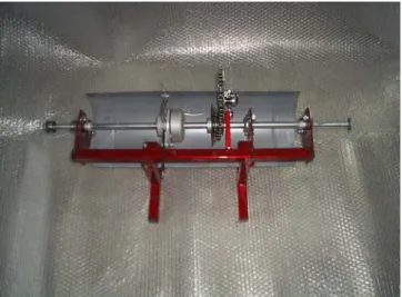
2.1 Design and construction of the assembly line A mechanical engineer and author have considered the design of the assembly line subject to the above limitations. Their 3D design can bee seen in the Figures 9 and 10. All of the features and dimensions have been based on the company experience,
including that of the technical manager the assembly worker team, and the author.
Figures 9 and 10 show images of the CAD designed assembly line that is proposed as a closed loop and has simple carriage units to transport the product through its assembly phases. A carriage unit has two axles and wheels based on standard bearings. The rails also are standard u type profiles. These standard parts reduce the cost of the assembly line
which is an important constraint for the company.
The carriage units can be moved forward and backward by the assembly workers and the number of the carriage units can be adjusted according to the product size, number of stations and so on. The general view of the CAD designed assembly line (Figure 9(a) and (b)) and some details of the carriage unit are shown in Figure 10(a) and (b). The stations could be placed suitable places around the loop.
Discussion with a focus on business considerations has led to a further simplified design to facilitate construction in the workshop at a low cost. The designed rail and carriage unit has been kept, but now configured as a simple linear design. This new Figure 3 Assembly section layout of the case study company before assembly line implementation
Supplied P
arts’
In
v
entory
Assembled and Packed Product Inventory Area
Tire, Rim, and Tube Inventory Area Lavatory and Lockers
Room
ASSEMBLY and INVENTORY Section
1,73m
Assembly and Inventory Area Assembly and Inventory Area
Assembly and Inventory Area
Tools
Tools and Small Parts
Tools and Small Parts
Figure 5 The frame of the tri-cycle
Figure 6 Front parts of the tri-cycle Figure 4 A tri-cycle for seniors
Figure 9 Designed assembly line for the case company
(a) (b)
Figure 10 Some details of the designed assembly line
(a) (b)
Figure 7 Rear section of the tri-cycle
configuration also allows convenient fitting within the assembly area floor space. This modification can be followed from the final assembly line layout in Figure 11 and the photographs (Figures 12-14). Total cost of the system was around $1,000. 2.2 The assembly chart of the tri-cycle for seniors balancing of the assembly line
Having manufactured the facility consideration was given to balancing the assembly stations for tri-cycle manufacture.
The Table I represents the bill of materials that is necessary for assembly of the product.
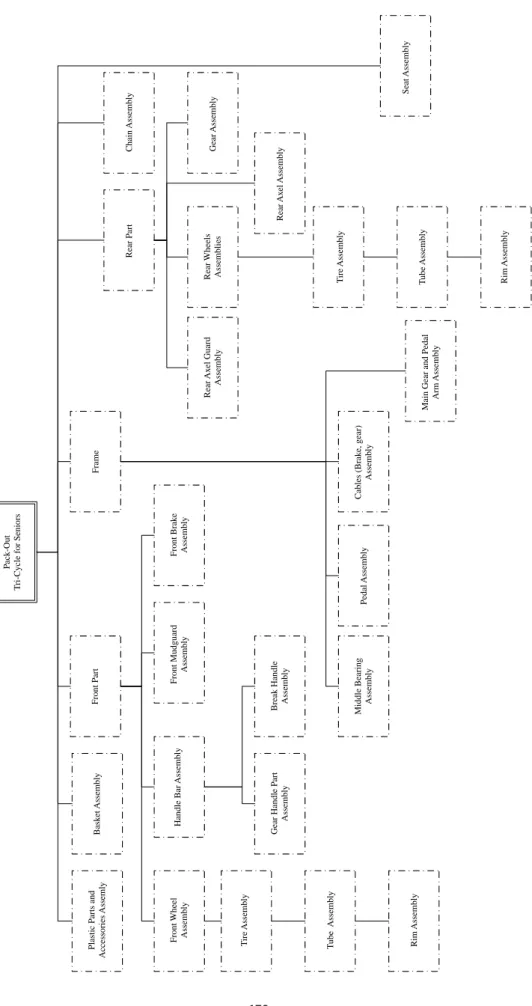
Assembly of these parts has been summarized as an assembly chart in the Figure 15.
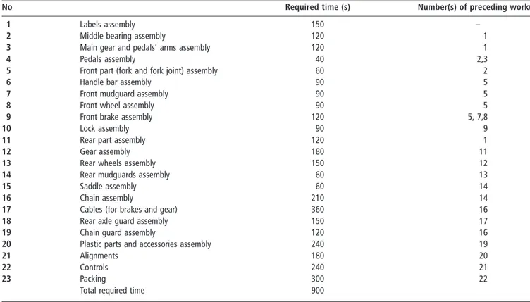
The table presents standard assembly times and
precedence of the work elements that have actually used
by the case study company. The data have been
derived through time and motions studies and proved by the company.
Figure 11 The assembly section of the company after the simple assembly line implementation
Control and Alignment Station1 Station 2 Station 3 Supplied P arts’ In v entory
Assembled and Packed Product Inventory Area
Tire,Rim, and Tube Inventory Area Station 4 for Labeling Handle Bar Subassembly Rear Part Subassembly Rim, Tube, Tire, Subassembly
Lavatory and Lockers Room
ASSEMBLY and INVENTORY Section
2.2.1 Assembly line balancing
To balance of the assembly line the cycle time for the product is required. The company uses 7.5 working hours/day and plans to assembly 30 tri-cycles per day to satisfy demand for the product. Thus, the product cycle time is 15 min:
C¼T
N
where C, cycle time; T, total working minutes in a day is 450
(8 £ 60 ¼ 4802 30); N, required product in a working day
(30); C ¼ 450/30 ¼ 15 min (900 s).
For assembly line balancing as described, for example, in Sule (1988) and Meyers and Stephens (2005) there are a number of heuristic rules that may be applied Sule (1988), Prac¸a and Ramos (1999), Rekiek et al. (2000) and Boysen et al. (2007). Also some more and specific mathematical details related with assembly line balancing may be gathered from Kara et al. (2007). From the assembly chart (Figure 15), and the standard time and precedence table (Table II), the assembly stations are constructed as set out in Table III. This balancing has been completed according to largest candidate rule; this method is a simple heuristic assembly line balancing method that is described fully in Sule (1988). This led to an initial assembly station design that was then refined through a series of discussions that included all stake holders. Final solution is presented in Table III.
2.3 Outputs from the assembly line solution
Practically, the assembly and manufacturing workers complete the subassemblies as their overtime. Mainly, the subassemblies are completed on workbenches in the assembly section.
After implementation of this assembly line, the company has experienced a number of significant benefits with further improvements expected as the facility is developed:
Figure 12 The assembly line that has been modified after design
Figure 13 Details of the assembly line
Figure 14 The 4th assembly station for alignments and controls
Table I The bill of materials of the tri-cycle
No Name of the part Quantity
1 Labels (items) 10 items
2 Middle bearing 1 unit
3 Pedals 2 units
4 Main gear and pedal arms 1 unit
5 Rear mudguards 2 units
6 Fork 1 unit
7 Fork joint 1 unit
8 Lock 1 unit
9 Front brake 1 unit
10 Front wheel (rim, spokes, hub, tube, and tire) 1 unit 11 Rear wheels (rims, spokes, hubs, tubes, and tires) 2 units
12 Gear (optional) 1 unit
13 Complete rear part (rear axle) 1 unit
14 Chain 2 m
15 Chain guard 1 unit
16 Rear brake 1 unit
17 Saddle 1 unit
18 Front mudguard 1 unit
19 Rear mirror 1 unit
20 Bell 1 unit
21 Rear axle guard 1 unit
22 Cables for gear and brakes 3.5 m
23 Basket 1 unit
Figure 15 Assembly chart of the tri-cycle for seniors
P
ack-Out
T
ri-Cycle for Seniors
Frame
Rear P
art
Front P
art
Front Wheel Assembly
Front Mudguard Assembly T ube Assembly Rim Assembly T ire Assembly Front Brak e Assembly Handle Bar Assembly Gear Handle P art Assembly
Break Handle Assembly
Pedal Assembly Middle Bearing Assembly Rear Ax el Assembly Seat Assembly
Chain Assembly Gear Assembly
Cables (Brak
e, gear)
Assembly
Rear Wheels Assemblies
T
ube Assembly Rim Assembly
T ire Assembly Bask et Assembly Rear Ax el Guard Assembly
Main Gear and Pedal
Arm Assembly
Plastic P
arts and
Table II Standard assembly times of parts and precedence of the work elements
No Required time (s) Number(s) of preceding work(s)
1 Labels assembly 150 –
2 Middle bearing assembly 120 1
3 Main gear and pedals’ arms assembly 120 1
4 Pedals assembly 40 2,3
5 Front part (fork and fork joint) assembly 60 2
6 Handle bar assembly 90 5
7 Front mudguard assembly 90 5
8 Front wheel assembly 90 5
9 Front brake assembly 120 5, 7,8
10 Lock assembly 90 9
11 Rear part assembly 120 1
12 Gear assembly 180 11
13 Rear wheels assembly 150 12
14 Rear mudguards assembly 60 13
15 Saddle assembly 60 14
16 Chain assembly 210 14
17 Cables (for brakes and gear) 360 16
18 Rear axle guard assembly 150 17
19 Chain guard assembly 120 16
20 Plastic parts and accessories assembly 240 19
21 Alignments 180 20
22 Controls 240 21
23 Packing 300 22
Total required time 900
Table III Assembly stations’ details for the case company and product
Work station Operation
Number of required workers Assigned tasks’ time (s) Cumulative task time (s) Available time of
work station (s) Deviation (s)
1 1 (Labels assembly) 1 150 840 900 60
2 (Middle bearing assembly) 120
3 (Main gear and pedals’ arms assembly) 120
5 (Front part (fork and fork joint) assembly) 60
7 (Front mudguard assembly) 90
8 (Front wheel assembly) 90
9 (Front brake assembly) 120
10 (Lock assembly) 90
2 4 (Pedals assembly) 1 40 870 900 30
6 (Handle bar assembly) 90
11(Rear part assembly 120
12 (Gear assembly) 180
14 (Rear wheels assembly) 150
16 (Chain assembly) 210
3 17 (Cables (for brakes and gear)) 1 360 870 900 30
18 (Rear axle guard assembly) 150
19 (Chain guard assembly) 120
20 (Plastic parts and accessories assembly) 240
4 13 (Rear mudguards assembly) 1 60 900 900 0
15 (Saddle and basket assembly) 60
21 (Alignments) 180
22 (Controls) 240
23 (Packing) 300
. The assembly part of the company can increase capacity of the final assembly from 12 to 30 tri-cycles in a shift with four final assembly workers.
. The assembly workers do not need long training (two to
three days training is enough for most unskilled workers).
. The quality of the final products has increased, these have
been measured by a reduction in return of defective products from customers.
. The assembly section in the company is now a tidy
working environment.
. The work in progress has been reduced (up to six
bicycles).
. Inventory management has been improved with a
reduction in part shortages.
. The management time of the entrepreneur has been
improved allowing opportunities to concentrate on other parts of the business, such as marketing.
3. Conclusions
SMEs are important for any national and international economy. They have to survive for the nation’s future. They face common problems and their problems that have to be solved to become well-established organizations. They have to use tools that are well established such as assembly lines, automation, information technology, etc.
In this study, a small manufacturing company which had final assembly capacity problem that included additional problems of quality, inventory and, etc. has been considered. This led to, an assembly line design, construction, and implementation designed according to constraints defined by the company. The stages have been presented to show how a small manufacturing company can get advantage from such
well-known solution approaches. From this design,
construction, and implementation:
. An assembly line can help to solve capacity problems in a
small manufacturing company that cannot afford high investments.
. A small manufacturing company can afford the design,
construction, and implementation costs of an assembly line.
. The design and usage of the assembly line has to be
modified according to the SME’s requirements.
. For the case study company, assembly capacity has been
increased from 12 to 30 products a day.
. The company quality has been increased; and their
requirements for highly skilled workers has been reduced. They can train an unskilled worker in two or three days for the final assembly.
4. Future works
The case study company could use the approach advocated in this study to target other achievements. The assembly line may be improved by adopting mixed product assembly that will also have an impact by reducing the inventory of parts and finished product.
References
Boysen, N., Fliedner, M. and School, A. (2007), “Assembly line balancing: which model to use when?”, International Journal of Production Researchin Press.
Gunasekaran, A. and Cecile, P. (1998), “Implementation of productivity improvement strategies in a small company”, Technovation, Vol. 18 No. 5, pp. 311-20.
Hu, M.W. and Schive, C. (1998), “The changing
competitiveness of Taiwan’s manufacturing SMEs”, Small Business Economics, Vol. 11 No. 4, pp. 315-26.
Imrek, B. (2002), “Common problems of small and medium size enterprises and solution suggestions”, MSc thesis, Institute of Science, Balikesir, (Turkish).
Kara, Y., Ozcan, U. and Peker, A. (2007), “Balancing and sequencing mixed model just in U-lines with multiple objectives”, Applied Mathematics and Computation, Vol. 184, pp. 566-88.
Kosgeb (2007), available at: www.kosgeb.gov.tr (accessed August 7, 2007)
Lamping, P. and Kuehl, C. (1997), Entrepreneurship, Prentice-Hall, Englewood Cliffs, NJ.
Meyers, F.E. and Stephens, M.P. (2005), Manufacturing Facilities Design and Material Handling, 3rd ed., Pearson Education, Upper Saddle River, NJ.
Peel, M. and Bridge, J. (1998), “How planning and capital budgeting improve SME performance”, Long Range Planning, Vol. 31 No. 6, pp. 848-56.
Prac¸a, I.S. and Ramos, C. (1999), “Multi-agent simulation for balancing of assembly lines”, Proceedings of the 1999 IEEE, International Symposium on Assembly and Task Planning, Port, Portugal, July.
Raymond, L., Jullien, P.A., Carriere, J.B. and Lachance, R. (1996), “Managing technological change in manufacturing SMEs: a multiple case analysis”, International Journal of Technology Management, Vol. 11 Nos 3/4, pp. 270-85. Rekiek, B., Lit, P.D. and Delchambre, A. (2000), “Designing
mixed-product assembly lines”, IEEE Transactions on Robotics and Automation, Vol. 16 No. 3, pp. 268-80. Sule, D.R. (1988), Manufacturing Facilities, Location Planning,
and Design, The PWS-Kent Series in Industrial
Engineering, Boston, MA.
Wilton, J.T. and Reavill, L.R.P. (1997), “The small or medium sized enterprise, its multinational client(s) and process-oriented change: a systems approach with case study”, Total Quality Management, Vol. 8 Nos 2/3, pp. 314-8.
Yaman, R., Imrek, B., Eid, S. and C¸ elik Yaman, G. (2003),
“Benefiting from internet and communication technology in solving some common problems facing small and
medium size enterprises”, Proceedings of the 31st
International Conference on Computers & Industrial
Engineering, San-Francisco, pp. 11-17.
Corresponding author
Ramazan Yaman can be contacted at: ryaman@balikesir.
edu.tr; [email protected]
To purchase reprints of this article please e-mail: [email protected] Or visit our web site for further details: www.emeraldinsight.com/reprints