See discussions, stats, and author profiles for this publication at: https://www.researchgate.net/publication/224648294
An efficient parallelization technique for high
throughput FFT-ASIPs
Conference Paper · June 2006 DOI: 10.1109/ISCAS.2006.1693920 · Source: IEEE Xplore CITATIONS5
READS62
6 authors, including: Harold Ishebabi Universität Potsdam 18 PUBLICATIONS 140 CITATIONS SEE PROFILE Oguzhan Atak ASELSAN Inc. 4 PUBLICATIONS 33 CITATIONS SEE PROFILE A. Atalar Bilkent University 175 PUBLICATIONS 4,140 CITATIONS SEE PROFILEAll content following this page was uploaded by A. Atalar on 04 October 2017.
An Efficient Parallelization Technique for High
Throughput FFT-ASIPs
H. Ishebabi, G. Ascheid, H. Meyr
Institute for Integrated Signal Processing Systems RWTH Aachen University, Aachen, Germany
O. Atak, A. Atalar, E. Arikan
Department of Electrical and Electronic Engineering Bilkent University, Ankara, Turkey
Abstract— Fast Fourier Transformation (FFT) and it’s inverse (IFFT) are used in Orthogonal Frequency Division Multiplexing (OFDM) systems for data (de)modulation. The transformations are the kernel tasks in an OFDM implementation, and are the most processing-intensive ones. Recent trends in the electronic consumer market require OFDM implementations to be flexible, making a trade-off between area, energy-efficiency, flexibility and timing a necessity. This has spurred the development of Application-Specific Instruction-Set Processors (ASIPs) for FFT processing. Parallelization is an architectural parameter that significantly influence design goals. This paper presents an analysis of the efficiency of parallelization techniques for an FFT-ASIP. It is shown that existing techniques are inefficient for high throughput applications such as Ultra Wideband (UWB), because of memory bottlenecks. Therefore, an interleaved execution technique which exploits temporal parallelism is proposed. With this technique, it is possible to meet the throughput requirement of UWB (409.6 Msamples/s) with only 4 non-trivial butterfly units for an ASIP that runs at 400MHz.
I. INTRODUCTION
Orthogonal Frequency Division Multiplexing (OFDM) is a multi-carrier modulation technique that has been adopted in various wireless communication standards such as Wire-less Local Area Networks (WLAN), Digital Video Broad-casting (DVB) and OFDM-based Ultra Wideband (UWB). The (de)modulation process uses Fast Fourier Transformation (FFT) and it’s inverse (IFFT). These transformations are the most computationally intensive tasks in an OFDM system [1]. Flexibility is a key requirement in wireless systems beyond 3G (B3G) [2], where modems can be reprogrammed or reconfigured to support different radio standards and operating modes. Consequently, Application Specific Instruction Set Processors (ASIPs) and Digital Signal Processor (DSPs) with special support for FFT processing have been developed to meet both flexibility and processing time constraints [3], [4]. In ASIPs, parallelization can be used to meet timing re-quirements (throughput). However, the type and degree of parallelization influence the efficiency of the implementation; both with respect to energy dissipation and area utilization. Therefore, we analyzed the efficiency of parallelization tech-niques under high throughput requirements, when applied to FFT-ASIPs. Area and energy consumption were taken as a measure of efficiency. The intention was to single out a parallelization technique with an outstanding efficiency for exploitation in FFT-ASIPs.
There is a substantial amount of publications on FFT par-allelization, however, the focus has been on general purpose, parallel and distributed computing domains. The recent emer-gence of methodology and tools for architecture exploration and automatic implementation such as LISA-based tools [5] enables this kind of analysis to be conducted for FFT-ASIPs as well.
The analysis reveals that existing parallelization techniques at the instruction and data level cannot efficiently meet high-throughput requirements such as 409.6 Msamples/s for UWB. This is caused by memory bottlenecks. Therefore, we propose the use of an interleaved execution technique which is capable of hiding some of the stage execution cycles by exploiting temporal parallelism. In this analysis, UWB was selected to demonstrate that it is feasible to implement instruction-set processors which can efficiently support, among other things, the computation of high-rate FFTs.
The rest of the paper is organized as follows: the imple-mented FFT algorithm and the FFT-ASIP architecture for analysis are presented in section II. The analysis for instruction and data level parallelization techniques are presented in sections III, followed by the proposed interleaved technique in sections IV and V. Concluding remarks are provided in section VI.
II. THEFFT ALGORITHM AND THEFFT-ASIP The Cooley-Tukey (CT) [6] algorithm has been widely adopted for FFT computation because of it’s regularity. A cached FFT (CFFT) algorithm which enables the exploita-tion of data locality for energy-efficient implementaexploita-tions was proposed in [7]. Figure 1 shows a comparison of energy consumption of two ASIPs for the two FFT algorithms. The ASIPs are described in detail in [8] and [9] respectively. Because of higher energy-efficiency, the CFFT-ASIP was selected for analysis. This ASIP is similar to the CT-ASIP: it has the same pipeline length, the same data-path width, the same memory configuration, and a butterfly instruction. This instruction calculates the addresses of the coefficients and data samples, fetches the operands, and computes the complete butterfly with a latency of 6 clock cycles. The maximum clock frequency of the ASIP is 250MHz. In the ASIP, a 32x32 register file is used as a cache. Both ASIPs were designed and
0.1 1 10 200 400 600 800 1000 E/uJ N
Energy Consumption for FFT Computation on Dedicated ASIPs Cooley-Tukey Cached FFT 0.1 1 10 200 400 600 800 1000 E/uJ N
Energy Consumption for FFT Computation on Dedicated ASIPs Cooley-Tukey
Cached FFT
Fig. 1. Energy dissipation of CT and CFFT ASIPs
implemented by using the same design flow and technology [8], [9].
In the cached algorithm, the FFT computation is divided into Epochs (E), Groups (G) and Passes (P) [7]. The following pseudo-code shows how the algorithm is implemented.
FOR e = 0 to E-1 FOR g = 0 to G-1 Load_Cache(e,g); FOR p = 0 to P-1 FOR b = 0 to NumBFLY-1 Butterfly(e,g,p,b); END END Dump_Cache(e,g); END END
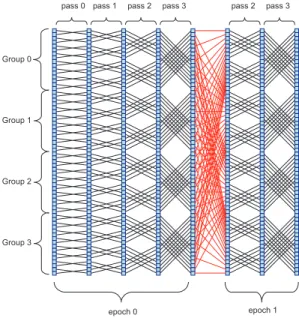
In this analysis, a modified version of the algorithm with a better cache utilization is used [9]. A better cache utilization is achieved through an uneven distribution of passes between the epochs. Figure 2 shows the flow graph for N=64 (cache size=16).
III. ANALYSIS OFEXISTINGPARALLELIZATION TECHNIQUES
On the architectural level, existing techniques can be grouped into Instruction, Data and Thread-Level Paralleliza-tion (ILP,DLP and TLP). Basically, the latter technique is use-ful for time-multiplexing the processor usage. Consequently, TLP cannot be used to increase the throughput of FFT computation on a dedicated ASIP.
Besides pipelining, ILP can be categorized according to instruction issue size: single and multiple issue. The latter can be further categorized into explicit (e.g. complex or fused instructions), static (e.g. VLIW) and dynamic issue (e.g. super scalar). However, since power consumption is a limiting factor, particularly for battery-powered modems, a dynamic issuing scheme is not considered.
Generally, longer pipelines increase the throughput of a pro-cessor. However, the analysis of power/performance metrics
Fig. 2. Data flow graph of the CFFT algorithm for N=64
with pipeline length shows that as the power consumption becomes more important in the metric, shorter pipelines tend to yield optimum results [10]. Since in this case power consumption is a concern, short pipelines are preferred. Nev-ertheless, by using more complex instructions (higher explicit-ness), a high throughput can be obtained with short pipelines. For a radix-2 FFT implementation, a butterfly instruction as described in section II offers the highest degree of explicit parallelization. However, this is not sufficient for meeting the throughput requirement as shown below.
In the CFFT-ASIP, the 4ns long critical path goes through the butterfly unit. The unit is distributed over three pipeline stages. By adding two additional stages, the critical path can be shortened to 2.5ns. In figure 3, the throughput of the ASIP is depicted for several FFT lengths. Clearly, the timing constraint for UWB cannot be met, even when a non-favorable 1ns clock is assumed to be possible.
For the last ILP alternative, the architecture was extended by three slots, so that four butterflies could be computed in parallel. Because of data dependencies between the passes [9], only a speed-up factor of 1.73 was achieved for N=128, which was far less than the required 11.41. This speed-up factor cannot be achieved by increasing the number of slots further due to a limited memory bandwidth, even with a 400MHz clock, since only 312.5ns/2.5ns=125 cycles are available for FFT processing (312.5ns is the OFDM symbol length in UWB). This is because cache loading and dumping alone already consume 256 cycles. The reason for this is the order of computation.
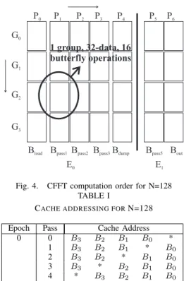
The FFT computation proceeds as shown in figure 4. In this case, there are 2 epochs, 4 groups and 7 passes. The groups are computed consecutively (0-3). In each group, the passes are computed in the order 0-4 for epoch 0, and 5-6 for epoch 1. Epoch 0 is computed first. Cache loading is done in passes 0 and 5, and the dumping in passes 4
0.1 1 10 100 0 100 200 300 400 500 600 700 800 900 1000 1100 micro sec N
FFT Computation Time for the CFFT-ASIP
UWB WLAN
DAB WiMAX
4ns Clock Period 2.5ns Clock Period (projected)
0.1 1 10 100 0 100 200 300 400 500 600 700 800 900 1000 1100 micro sec N
FFT Computation Time for the CFFT-ASIP
UWB WLAN
DAB WiMAX
4ns Clock Period 2.5ns Clock Period (projected)
0.1 1 10 100 0 100 200 300 400 500 600 700 800 900 1000 1100 micro sec N
FFT Computation Time for the CFFT-ASIP
UWB WLAN
DAB WiMAX
4ns Clock Period 2.5ns Clock Period (projected)
Fig. 3. FFT computation time for CFFT-ASIP
and 6. Cache dumping is done concurrently with Non-Trivial Butterfly (NBF) computation. In epoch 0, cache loading is also concurrently done, however, the butterflies are trivial since in all cases the coefficient is1 + 0i, where i =√−1. In epoch 1, the cache is separately loaded. Since a dual port data memory was used, 256 cycles were needed loading and dumping.
The memory bandwidth can be increased by partitioning the memory with a similar scheme as in [11]. If, for instance, 32 data samples (cache size) can be accessed concurrently, then at least
448 butterfly cycles − 64 trivial butterfly cycles 125 cycles − 56 control cycles − 8 load/dump cycles= 7 NBF units would be required to achieve the throughput at 400MHz, with a correspondingly very high area and energy consumption. This is the minimum number of NBF units. A mixed-radix approach such as [12] would lead to a low area cost because of higher-radix. However, a similar approach is not applicable in this case for flexibility reasons.
For DLP, the analysis and the results are similar to the preceding ones. The difference is that in DLP techniques such as vector instructions, only one instruction would be decoded, rather than 7 as in the above 7-slot VLIW.
A careful analysis of computation order reveals that it is possible to interleave the execution, so that the throughput is achieved with only 4 NBF units, and with no memory partitioning. This technique is described in the following section.
IV. INTERLEAVEDEXECUTION
The idea behind interleaved execution is to hide some of the execution cycles through instruction scheduling. This means, as opposed to ILP techniques, temporal parallelism between the passes is exploited, rather than spatial parallelism in the groups. In subsequent discussion, a latency of 3 cycles for the actual execution of a butterfly is assumed.
With the preceding ILP technique in section III, the order of computation (figure 4) isG0: P0−P4, G1: P0−P4, · · · , G3: P0 − P4, G0 : P5 − P6, · · · , G3 : P5 − P6 [7], [9]. Table
I shows the cache addressing for N=128 [7], [9]. The star
Fig. 4. CFFT computation order for N=128 TABLE I
CACHE ADDRESSING FORN=128 Epoch Pass Cache Address
0 0 B3 B2 B1 B0 * 1 B3 B2 B1 * B0 2 B3 B2 * B1 B0 3 B3 * B2 B1 B0 4 * B3 B2 B1 B0 1 3 B3 * B2 B1 B0 4 * B3 B2 B1 B0
in the table has the values 0 and 1 for the two data of the butterfly respectively. The pass number determines the position of the star. With this table, and with the pipeline model, it follows that the first 2 operands for computation of G0 : P1
are available 3 cycles afterG0: P0has started. The next 2 after
4 cycles, etc. Similarly, forG0: P2, the operands are available
6, 7, 8, · · · cycles after G0: P1has started, etc. Therefore, the
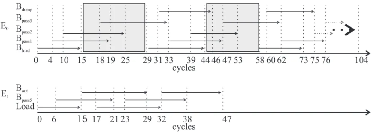
execution can be interleaved as shown in figure 5. The next group (G1 : P0) cannot start until the first 2 cache elements
has been dumped inG0: P4. However, because of a latency
of 3 cycles, the next loading can start 2 cycles prior to the dumping as shown in the figure. In this way, epoch 0 can be processed in 105 cycles. Similarly, epoch 1 can be finished in 48 cycles, making a total of 153 cycles for N=128, so that the cycle constraint from section II is violated by 153-125=28 cycles. This is largely attributed to 13 cycles between each cache loading between the groups (greyed area in figure 5). If these 13 cycles are removed, then the total number of cycles can be reduced by 13x3=39.
Since in each cycle Bload loads 2 cache registers, addi-tional 26 cache registers are required. This would only add approximately 30KGates to the CFFT-ASIP, which has, in the current version, 430KGates (of which 63% are occupied by memories). To simplify cache addressing in presence of additional buffering registers, a modulo addressing scheme can be used.
The execution of control and initialization instructions can also be interleaved, so that the associated cycles are completely hidden. This technique requires a different instructions execu-tion sequencing. A corresponding execuexecu-tion model is proposed in the following section.
Fig. 5. Interleaving scheme V. EXECUTIONMODEL
In mainstream processor architectures, each execution is immediately preceded by instruction fetching and decoding in absence of hazards. Therefore, with such an execution model, it is not possible to interleave instructions without having to unroll all iterations. A data-triggered execution model can solve this problem. A Transport Triggered Architecture (TTA) which is data-triggered is proposed in [13]. However, TTA targets at reducing bypass complexity, rather than exploiting temporal parallelism.
Therefore, the following execution model is proposed: After fetching and decoding, an execution unit is conditionally scheduled for execution. The condition is specified by the programmer. If scheduled for execution, the corresponding operation remains pending until another condition is fulfilled. The latter is internally generated in the processor by other instructions, similarly to flags setting. Such a condition could for instance be the availability of operands (data-triggering). The pending operation does not block the further sequencing of instructions, rather, it enters a pending slot, while the processor continues to fetch and decode other instructions. The execution condition is polled in each cycle until it becomes true. Thereafter, the operation is executed concurrently to any other activated operation. After execution, the condition is automatically toggled back to false, and the operation is emptied from the pending slot.
In this execution model, Zero Overhead Loops (ZOLs) are non-blocking, i.e. when the initialization of a ZOL is encountered, the ZOL is started, and the following instruction is fetched. If the following instruction has to wait, then the sequencing of instruction has to be explicitly suspended, until a required condition is fulfilled.
VI. SUMMARY ANDCONCLUSION
In this paper, it has been shown that existing parallelization techniques cannot be efficiently utilized in FFT-ASIPs for high throughput applications such as UWB. An interleaved execution technique which can meet the throughput require-ment is therefore proposed, together with the corresponding execution model. With this technique, only 4 NBF units are required. Currently, we are extending the CFFT-ASIP to support interleaved execution. Based on the results of the 4-slot
VLIW extension, the area is expected to increase by 28% to 550.4KGates (7% due to additional cache registers, 21% due to additional NBF units). UWB was selected to demonstrate that it is feasible to implement instruction-set processors which can efficiently support, among other things, the computation of high-rate FFTs.
ACKNOWLEDGEMENTS
This work has been partially funded by the European Commission through the Network of Excellence in Wireless COMmunications (Newcom).
REFERENCES
[1] L. Hanzo, M. Mnster, B. Choi, and T. Keller, OFDM and MC-CDMA for broadband multi-user communications, WLANs and broadcasting. Chichester, UK: Wiley, 2003.
[2] J. Mitola, Software radio architecture : object-oriented approaches to wireless systems engineering. New York: Wiley, 2000.
[3] K. Heo, S. Cho, J. Lee, and M. Sunwoo, “Application-specific dsp architecture for fast fourier transform,” in IEEE International Conference on Application-Specific Systems, Architectures, and Processors, June 2003, pp. 369– 377.
[4] CARMEL DSP Core Data Sheet, Infineon Technologies Inc., 1999. [5] Schliebusch, O. and Chattopadhyay, A. and Kammler, D. and Ascheid,
D. and Leupers, R. and Meyr, H. and Kogel, T., “A Framework for Automated and Optimized ASIP Implementation Supporting Multiple Hardware Description Languages,” in ASP-DAC, Shanghai, China, Jan 2005.
[6] R. Blahut, Fast Algorithms for Digital Signal Processing. Reading, MS: Addison-Wesley Publishing Company, 1985.
[7] B. M. Baas, “A low-power, high-performance, 1024-point fft processor,” in IEEE Journal of Solid-State Circuit, vol. 34, no. 3, 1999, pp. 380–387. [8] Ishebabi, H., Kammler, D., Ascheid, G., Meyr, H., Nicola, M., Masera, G., Zamboni, M., “FFT processor: a case study in ASIP development,” in IST, Dresden, Germany, June 2005.
[9] Ishebabi, H., Kammler, D., Ascheid, G., Meyr, H., Atak, O., Atalar, A., Arikan, E., Nicola, M., Masera, G., Zamboni, M., “DESIGN OF APPLICATION SPECIFIC PROCESSORS FOR THE CACHED FFT ALGORITHM,” in ICASSP, Toulouse, France, May 2006.
[10] A. Hartstein and T. R. Puzak, “Optimum power/performance pipeline depth,” in MICRO 36: Proceedings of the 36th annual IEEE/ACM International Symposium on Microarchitecture. Washington, DC, USA: IEEE Computer Society, 2003, p. 117.
[11] J. Takala, T. Jarvinen, and H. Sorokin, “Conflict-free parallel memory access scheme for fft processors,” in Proceedings of the 2003 Interna-tional Symposium on Circuits and Systems, vol. 4, 2003, pp. IV–524 – IV–527.
[12] Y.-W. Lin, H.-Y. Liu, and C.-Y. Lee, “A 1-gs/s fft/ifft processor for uwb applications,” in IEEE Journal of Solid-State Circuits, vol. 40, no. 8, August 2005, pp. 1726–1735.
[13] H. Corporaal, Microprocessor Architectures: From VLIW to Tta. New York, NY, USA: John Wiley & Sons, Inc., 1997.
View publication stats View publication stats