Adıyaman Üniversitesi
Mühendislik Bilimleri Dergisi
10 (2019) 250-264
AN ANALYTICAL AND EXPERIMENTAL APPROACH FOR
IMPROVED STIFFNESS MATRIX OF BARS WITH SHEAR AND WIDE
SUPPORT EFFECTS
Yaşar AYAZ
1*, Ahmet BUDAK
21 Department of Civil Engineering, Faculty of Engineering, Inonu University, 44280 Malatya, Turkey 2 Department of Civil Engineering, Faculty of Engineering, Atatürk University, 25240 Erzurum Turkey
Geliş tarihi: 22.04.2019 Kabul tarihi: 16.05.2019
ABSTRACT
In this study, frames including both the shear and the wide support effect were examined analytically, numerically and experimentally. Stiffness method was used for analytical solution and finite element method was used for numerical solution. Explicit expressions for the stiffness matrix that includes both the shear effect and the wide support effect are presented. A model frame was tested experimentally, and a maximum deflection result was obtained. The same frame was modeled and solved with the finite element method and with the proposed method. The results of three methods were compared. The proposed method was verified successfully. The proposed method, which includes both the shear and wide support effects, produced results that were shown to be closer to the experimental results and the results than were the results of the other models that were investigated.
Keywords: Shear effect, wide support effect, rigid end zone, stiffness matrix, finite element
KAYMA VE GENİŞ MESNET ETKİSİNDEKİ ÇUBUKLARIN
GELİŞTİRİLMİŞ RİJİTLİK MATRİSLERİ İÇİN ANALİTİK VE
DENEYSEL BİR YAKLAŞIM
ÖZET
Bu çalışmada, aynı anda hem kayma ve hem geniş mesnet etkisindeki çerçeveler analitik, nümerik ve deneysel olarak incelenmiştir. Analitik çözüm için matris deplasman yöntemi, sayısal çözüm için sonlu elemanlar yöntemi kullanılmıştır. Hem kayma etkisi hem de geniş mesnet etkisini içeren rijitlik matrisi için açık denklemler ortaya konmuştur. Bunun için bir model çerçeve deneysel olarak test edildi ve maksimum çökme değeri elde edildi. Aynı çerçeve sonlu elemanlar yöntemi ile modellenerek ve ayrıca önerilen yöntem ile de çözüldü. Üç yöntemin sonuçları karşılaştırıldı. Önerilen yöntem başarıyla doğrulandı. Hem kayma hem de geniş destek etkilerini içeren önerilen yöntem sonuçlarının, deneysel sonuçlara ve sonlu elemanlar yöntemi sonuçlarına daha yakın olduğu görülmüştür.
Anahtar Kelimeler: Kayma etkisi, geniş destek etkisi, rijit uç bölge, rijitlik matrisi, sonlu elemanlar
1. Introduction
Many studies analyze frames with the matrix method [1-12]. After the use of computers become common, matrix methods became more popular. The addition of the shear effect to the matrix method is also very common and is well established [7,12]. Despite its large effect, the wide support effect is generally neglected. In the solution of bar elements, the bar length is considered to be the length between nodes. This length does not represent the bar length exactly in frames. The intersection of the column and the beam is different from both the column and the beam. This part is called the wide support or the rigid end zone. In frames, the bar length does not start from the node points. A bar length started from the node points causes inaccuracy in the results. Increasing the bar height increases the common component, and this causes unacceptable errors in the results.
In the stiffness method main problem is to obtain stiffness matrix. After the construction of the stiffness matrix the problem is solved systematically. In previous studies only one effect is handled in the stiffness matrix. In this study, the stiffness matrix including both the shear and wide support effects was developed and explicit formulations for stiffness members are given. By using this formulation, it is possible to obtain stiffness matrix for normal solution, shear effect, wide support effect and their combinations (bare solution, only shear effect, only wide support effect and both shear and wide support effects). The results obtained from proposed method were also verified experimentally. For this purpose, a frame was solved for with the proposed method. For experimental verification, the same frame was tested, and the maximum deflection value was obtained. A finite element method (FEM) model for this frame was created. The results of three methods are compared. Two different frames were solved for with the proposed methods, and the results are compared with the FEM results. The results of the proposed method were consistent with the FEM results. In the case of the cantilever beam, where only the shear effect is present, the proposed method also has been proven theoretically. In the frame example, the results of the proposed method and FEM results and experimental results were consistent.
2. Theoretical
2.1. Shear effect in uniform members
The stiffness matrix in local coordinates for plane frame members can be expressed as follows:
[ ]
−
−
−
−
−
=
j j j j i i i i j iA
C
B
C
C
D
C
D
B
C
A
C
C
D
C
D
k
(1)where Ai, Aj and B are stiffness members and are defined as
L EI a
Ai = i , Aj =aj EIL , B =bij EIL . (2)
The other stiffness matrix members are defined as follows:
L
C
C
D
L
B
A
C
L
B
A
C
j i j j i i+
=
+
=
+
=
,
,
. (3)For uniform cross-section members without shear effect, the stiffness coefficients are ai=aj=4 and bij=2 [5,7].
The shear effect is neglected in most mechanical problems because of its small value. Generally, the decision to neglect the shear effect is made according to the length / height ratio (L/h) of the members. Shear effect increases with increases in the height and decreases in the L/h ratio. The shear effect should be considered if the L/h ratio is less than 10 [7,13].
Figure 1. Consideration of the shear effect [7].
To include the shear effect in the stiffness members, moment Ai and vertical force Ci are applied to the beam in Fig. 1. The coefficients of the moments that cause unit rotation in node i produce the Ai and Bij stiffness coefficients. θA ' and θA '' represent the absolute value of rotation, and dA' and dA'' represent the absolute value of displacement caused by the Ai moment and the Ci vertical force applied to node i and θA and dA represent rotation and deflection at point A respectively. Considering unit rotation at node i,
1
''
'
−
A=
Aθ
θ
(4) from which1
2
2=
−
EI
L
C
EI
L
A
i i (5)Considering zero rotation,
0
''
'
+
=
−
d
Ad
A (6) from which0
)
'
3
(
2
3 2=
+
+
−
AG
L
C
k
EI
L
C
EI
L
A
i i i . (7)From the equilibrium between nodes i and j, Ci can be calculated as
L
B
A
C
i ij i+
=
. (8) 1 Bi Ci Ci L L'
Ad
+ j i AiEI
L
A
d
EI
L
A
i A i A'
;
'
2
2=
=
θ
AG
L
C
k
EI
L
C
d
EI
L
C
i i A i A''
2
;
''
3
'
3 2+
=
=
θ
+ =0
1
=
=
A Ad
θ
(a) (b) (c)''
Ad
'
Aθ
''
Aθ
'
iA
By solving equations 5 and 7, i i EIL A =4
λ
(9) ij ij EIL B =2λ
(10)are obtained. Because of symmetricity, Ai=Aj. The correction factors for the shear effect in the stiffness matrix are
25 . 0 75 . 0 + = =
λ
ε
λ
i j (11)5
.
0
5
.
1
−
=
ε
λ
ij (12) where (13)For a rectangular shape, k' is the shape factor (and is equal to 1.2) and µ is the Poisson ratio. Consequently, we obtain 2
)
(
76
.
2
1
1
h
L
+
=
ε
. (14)By using the λi and λj coefficients, the shear effect is included in the stiffness matrix [7].
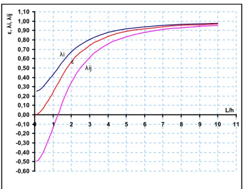
Figure 2. λi, λj and ε values as a function of the L/h ratio for μ=0.3 and k'=1.2[7 -0,60 -0,50 -0,40 -0,30 -0,20 -0,10 0,00 0,10 0,20 0,30 0,40 0,50 0,60 0,70 0,80 0,90 1,00 1,10 0 1 2 3 4 5 6 7 8 9 10 11 L/h ε, λ i, λij ε λi λij
The values of the correction factors λi, λj and ε as a function of the L/h ratio for μ=0.3 and k'=1.2 are plotted in Fig. 2. As can be seen in Fig. 2, the values of λi, λj and ε approach 1 as the L/h ratio increases to 10.
2.2. Wide Support Condition
The wide support effect has a greater effect than the shear effect in most conditions. On the contrary, however, in most studies the shear effect is considered while the wide support effect is neglected. In classical beam theory when a frame member is solved in one dimension, such as is done for a bar element, the member length is selected between two nodes. In fact, the intersection of the column and beam is different from the column and the beam. This segment cannot be considered in the beam or the column length. To consider the intersection of the column and the beam as part of the column or as part of the beam introduces a large error into the solution. The size of this common segment grows as the member height increases, and this increases the error in the result. This segment that must be treated differently from the beam and the column is called the wide support or the rigid end zone. For a wide support, the stiffness matrix and the fixed end forces change and have to be regenerated. Tezcan solved this problem with rigid rotation of this part[7].
Figure 3. Wide support in a frame.
As seen in Fig. 3, first, the common segment in the beam-column is assumed to be totally rigid. By adding additional deformation caused by rigid rotation of this block, the stiffness members for the wide support condition are calculated. e1 and e2 represent the half-length of nodes i and j, respectively. The {d'} deformation on the nodes of the free beam length (i'-j') can be written with the help of the {d} deformation on nodes of theoretical length [7],
{ }
d =
'
[ ]
T
{ }
d
. (15)By means of rigid rotation of the column-beam intersection segment, the deformation relations between the real length and the theoretical length of the beam can be derived.
L0 L
e1 e2
i j
Figure 4. Deformation relation in wide support members[7].
[T] = transformation matrix for displacement e1= support half length at node i
e2= support half length at node j
From Fig. 4, the relation between d and d' can be written as
4 4 4 2 3 3 2 2 2 1 1 1
'
'
'
'
d
d
d
e
d
d
d
d
d
e
d
d
=
−
=
=
+
=
(16) In matrix form,{ }
=
'
'
'
'
'
4 3 2 1d
d
d
d
d
(17){ }
=
4 3 2 1d
d
d
d
d
(18)[ ]
−
=
1
0
0
0
1
0
0
0
0
1
0
0
0
1
2 1e
e
T
(19) e1 d4 d1 d2 d11 e1d2 d21= d2 e2d4 d41=d4 d3 d31De2{ }
−
=
4 3 2 1 2 11
0
0
0
1
0
0
0
0
1
0
0
0
1
'
d
d
d
d
e
e
d
(20)When the transformation matrix [T] and the stiffness matrix
[ ]
k
'
as a function of the free length of the beam are known, the stiffness matrix as a function of the theoretical nodes [k] can be calculated as follows:[ ] [ ] [ ][ ]
k = T T k' T . (21) Because the common deformations of the system are on nodes i and j, the stiffness matrix used to find the system stiffness matrix is [k]. The stiffness matrix [k'] of the free length between i' and j' can be written as follows:[ ]
−
−
−
−
−
−
=
'
'
'
'
'
'
'
'
'
'
'
'
'
'
'
'
'
j j j j i i i i j iA
C
B
C
C
D
C
D
B
C
A
C
C
D
C
D
k
(22)where L0 is the free length of the member or the beam and
0 0 0
'
,
'
,
'
L
EI
b
B
L
EI
a
A
L
EI
a
A
i=
i j=
j=
ij (23) and 0 0 0'
'
'
,
'
'
'
,'
'
'
L
C
C
D
L
B
A
C
L
B
A
C
j i j j i i+
=
+
=
+
=
(24)From equation (21), the stiffness matrix transformed to theoretical nodes is
[ ]
+
+
−
−
+
+
+
+
−
−
−
−
−
+
+
+
−
−
+
+
+
+
−
+
=
'
'
2
'
'
'
'
'
'
'
'
'
'
'
'
'
'
'
'
'
'
'
'
'
'
2
'
'
'
'
'
'
'
'
'
2 2 2 2 2 1 2 1 2 2 1 2 1 2 1 1 1 2 1 1 2 1D
e
C
e
A
C
D
e
D
e
e
C
e
C
e
B
D
e
C
C
D
e
D
C
D
e
D
D
e
e
C
e
C
e
B
C
D
e
A
C
e
D
e
D
e
C
C
D
e
D
C
D
e
D
k
j j j i j j j i i j i i i i j i (25)[ ]
+ + + − + + + + + − + − − + + + + − + + + − + = 3 2 2 2 2 32 3 2 2 1 2 1 32 32 3 31 3 3 2 2 1 2 1 31 3 2 1 2 1 31 32 3 31 3 ) 3 3 ( 4 ) 2 ( 6 ) ) ( 3 6 ( 2 ) 2 ( 6 ) 2 ( 6 12 ) 2 ( 6 12 ) ) ( 3 6 ( 2 ) 2 ( 6 ) 3 3 ( 4 ) 2 ( 6 ) 2 ( 6 12 ) 2 ( 6 12 L L L e e EI L L e EI L L L e e e e EI L L e EI L L e EI L EI L L e EI L EI L L L e e e e EI L L e EI L L L e e EI L L e EI L L e EI L EI L L e EI L EI k (26)Rigid rotation of the common segment affects the fixed end forces in the wide support condition. The relation between the forces is seen in Fig. 5 and is derived as
Figure 5. Force relations for the wide support condition[7].
3 2 4 4 3 3 1 1 2 2 1 1
'
'
'
'
p
e
p
p
p
p
p
e
p
p
p
p
+
=
=
−
=
=
(27) 3 2 4 4 3 3 1 1 2 2 1 1'
'
'
'
p
e
p
p
p
p
p
e
p
p
p
p
−
=
=
+
=
=
(28)The fixed end forces and the node forces on the free length i'-j' nodes are transformed to theoretical length i-j nodes by using the following equations [7]:
{𝑓𝑓} = [𝑇𝑇]𝑇𝑇{𝑓𝑓′} (29) and
{ }
p =[ ]
T T{ }
p' . (30) e1 P4 P1 P2'
3P
'
3P
e2 P1’ P2’'
3P
'
1P
'
2P
2.3. Shear effect on wide support conditions
In the previous sections, the shear effect and the wide support effect are investigated individually. When the height of the member increases, both the wide support and the shear effects increase. Therefore, both effects must be considered simultaneously. A stiffness matrix needs to be developed to consider both effects.
The stiffness members for the shear effect in uniform cross-section members are
i i EIL A =4
λ
j j EIL A =4λ
ij ij EIL B =2λ
L C C D L B A C L B A Ci i j j i j + = + = + = , , .Taking both the shear and wide support effects of equation (31) into account, the free length L0 is used to obtain the stiffness matrix. Therefore, the stiffness members are obtained as follows:
i i LEI A
λ
0 4 '= j j EIL Aλ
0 4 '= ij ijL
EI
B
λ
02
'=
0 0 0'
'
'
'
'
'
,'
'
'
L
C
C
D
and n
L
B
A
C
L
B
A
C
j i j j i i+
=
+
=
+
=
The stiffness matrix
[ ]
k
'
for the free length is given in equation (22), and the transformation matrix [T] for displacement in the wide support condition is given in equation (19). The stiffness matrix for theoretical nodes [k] is given in equation (21) and is [k]=[T]T [k'] [T]. The products of the right-hand side are re-written as follows:[ ]
+
+
−
−
+
+
+
+
−
−
−
−
−
+
+
+
−
−
+
+
+
+
−
+
=
'
'
2
'
'
'
'
'
'
'
'
'
'
'
'
'
'
'
'
'
'
'
'
'
'
'
2
'
'
'
'
'
'
'
'
'
2 2 2 2 2 1 2 1 2 2 1 2 1 2 1 1 2 1 1 1 2 1D
e
C
e
A
D
e
C
D
e
e
C
e
C
e
B
D
e
C
D
e
C
D
D
e
C
D
D
e
e
C
e
C
e
B
D
e
C
D
e
C
e
A
D
e
C
D
e
C
D
D
e
C
D
k
j j j i j j j i i j i i i i j i (33)This stiffness matrix includes both the shear and wide support effects for uniform cross-section members. The stiffness members are generally shown by kij, where i and j represent the row and the (31)
h2 h1 e1 e2 P=400kgf 9.7 cm 9.8 cm 79.5 cm A B 99.5 cm
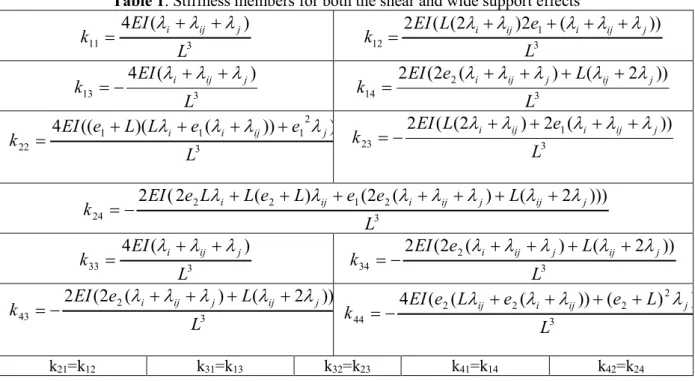
column number, respectively. The stiffness members for both the shear and wide support effects are given in Table 1.
Table 1. Stiffness members for both the shear and wide support effects
3 11
)
(
4
L
EI
k
=
λ
i+
λ
ij+
λ
j 3 1 12))
(
2
)
2
(
(
2
L
e
L
EI
k
=
λ
i+
λ
ij+
λ
i+
λ
ij+
λ
j 3 13)
(
4
L
EI
k
=
−
λ
i+
λ
ij+
λ
j 3 2 14))
2
(
)
(
2
(
2
L
L
e
EI
k
=
λ
i+
λ
ij+
λ
j+
λ
ij+
λ
j 3 2 1 1 1 22)
))
(
)(
((
4
L
e
e
L
L
e
EI
k
=
+
λ
i+
λ
i+
λ
ij+
λ
j 3 1 23))
(
2
)
2
(
(
2
L
e
L
EI
k
=
−
λ
i+
λ
ij+
λ
i+
λ
ij+
λ
j 3 2 1 2 2 24)))
2
(
)
(
2
(
)
(
2
(
2
L
L
e
e
L
e
L
L
e
EI
k
=
−
λ
i+
+
λ
ij+
λ
i+
λ
ij+
λ
j+
λ
ij+
λ
j 3 33)
(
4
L
EI
k
=
λ
i+
λ
ij+
λ
j 3 2 34))
2
(
)
(
2
(
2
L
L
e
EI
k
=
−
λ
i+
λ
ij+
λ
j+
λ
ij+
λ
j 3 2 43))
2
(
)
(
2
(
2
L
L
e
EI
k
=
−
λ
i+
λ
ij+
λ
j+
λ
ij+
λ
j 3 2 2 2 2 44)
)
(
))
(
(
(
4
L
L
e
e
L
e
EI
k
=
−
λ
ij+
λ
i+
λ
ij+
+
λ
j k21=k12 k31=k13 k32=k23 k41=k14 k42=k243. Experimental
To verify the results provided by the proposed method and by FEM and to observe the exact behavior of the models, experimental test was carried out. An experimental model frame was produced from S220 steel. Specimens were produced from used material, and the modulus of elasticity was determined. The modulus of elasticity (E) for model 1 was calculated, with the help of the tensile test, to be 202,016.99 MPa. The Poisson ratio was taken as 0.3.
The experimental model was fabricated to give measurable results and to have a wide support effect (Fig. 6). A dial gauge was used to observe movement and rotation on the support. The loads were selected as the maximum of the elastic limit and the buckling load. The tests were repeated 10 times for model 1 and the averages of the results were used.
Figure 6. Model 1 with concentrated loading (left), e1 and e2 on a wide support (middle) and the mesh system in the FEM model (right).
4. Finite Element Modeling
In this study, a 2-D, eight-node element PLANE82, which provides more accurate results and can tolerate irregular shapes, is used. The PLANE82 geometry and stress output are shown in Figs. 7 and 8.
Figure 7. PLANE82 geometry (2-D, eight-node structural solid)[14].
Figure 8. PLANE82 stress output[14].
PLANE82 is a higher-order version of the 2-D, four-node element PLANE42. The eight-node elements have compatible displacement shapes and are well suited to model curved boundaries. The eight-node element is defined by eight nodes having two degrees of freedom at each node: translations in the nodal x and y directions. The element may be used as a plane element or as an axisymmetric element. The element has plasticity, creep, swelling, stress stiffening, large deflection and large strain capabilities [14].
5. Results
5.1. Analytical method verification
Figure 9. Uniform cantilever member
Table 2. Comparison of proposed method and FEM solution.
Deflection at B, for example 2 in Table 2, is 𝑦𝑦𝐵𝐵 =𝑤𝑤𝐿𝐿
2
8𝐸𝐸𝐸𝐸 , with shear effect deflection is 𝑦𝑦𝐵𝐵= 𝑤𝑤𝐿𝐿2
8𝐸𝐸𝐸𝐸+ 𝑘𝑘 𝑤𝑤𝐿𝐿2
2𝐺𝐺𝐺𝐺. And it is calculated as 𝑦𝑦𝐵𝐵 = 93,75 + 3,549 = 97,299 mm. The proposed method gives
nearly same result of bar solution as 𝑦𝑦𝐵𝐵 = 93,75 + 3,55 = 97,30 mm. So that proposed method is
verified. Bar solution and FEM solution give nearly same result if shear effect is considered in bar solution. Even in example 4 where L/h is very small as 1.7, BAR solution give good result if shear effect is considered. Q L2 B H2 L1 B=1 m Q=10 t/m E=100.000kg/m2 ν=0.2 A H1
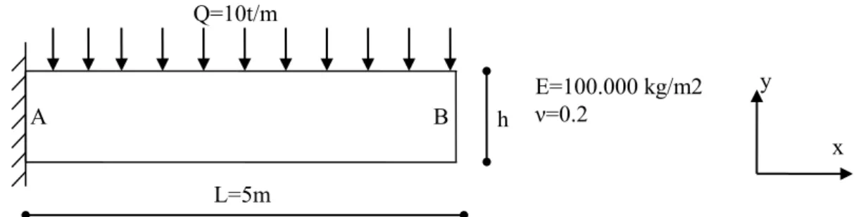
Figure 10. Frame with uniform members.
Ex am pl e H[m] L[m] L/h Deflection at B (mm) FEM-BAR ( %) BAR-BAR+S (%) FEM-BAR+S (%)
FEM BAR BAR+S
1 0.5 5 10 -755.09 -750 -757.12 0.67 0.95 0.27 2 1 5 5 -97.10 -93.75 -97.30 3.45 3.79 0.2 3 2 5 2,5 -13.51 -11.72 -13.49 13.26 15.1 0.16 4 3 5 1,7 -4.67 -3.47 -4.66 25.75 34.29 0.29 L=5m h Q=10t/m E=100.000 kg/m2 ν=0.2 B A y x
Table 3. Shear effect in frame with different L/h value.
Example Element dimensions(m) Deflection at B (mm) Difference (%) H1 H2 L1 L2 L/h BAR BAR+S FEM FEM-BAR BAR+S FEM-1 0.2 0.2 5.5 5.5 27.5 -79726.1 -79749.2 -78678 1.33 1.36 2 0.5 0.5 5.5 5.5 11 -4563.7 -4571.03 -4451 2.53 2.7 3 1 1 5.5 5.5 5.5 -471.25 -474.8 -445.08 5.88 6.68 4 1.5 1.5 5.5 5.5 3.67 -114.63 -116.77 -105.29 8.87 10.9 5 2 2 5.5 5.5 2.75 -39.46 -40.89 -35.031 12.64 16.73
In contrast to examples of Table 2, in frames as seen in table 3 addition of shear effect deviate BAR results from FEM results. In example 5 differences in between FEM and BAR results is 12.64% without shear effect in bar solution. But addition of shear effect increase difference to 16.73%. Therefore, in frames wide support effect should be considered to eliminate this difference.
5.2. Experimental Results
The experimental deflection of point B (EXP) of Model 1, shown in Fig. 6, is given in Table 4 and compared with the deflection of point B obtained with the normal bar solution (BAR), the bar solution including only the shear effect (BAR+S), the bar solution including only the wide support effect (BAR+W), the bar solution including both the shear and wide support effects (BAR+S+W) and the finite element method (FEM) solution.
It can be seen from Table 4 that the experimental result is within 1% of the proposed method solution (BAR+S+W), which includes both the shear and wide support effects.
Table 4. Experimental result of Model 1 and comparison to FEM and the proposed method
results.
Column no 1 2 3 4 5 6
TEST 1
(E=202016.99MPa) BAR BAR+S BAR+W ( e = h/2 ) BAR+S+W ( e =h/2 ) FEM EXPERIMENT Deflection at B
(mm) 16.4909 16.5347 15.1790 15.2178 15.3290 15.3010 Ratio to
experimental result 1.078 1.081 0.992 0.995 1.002 1.000
Table 5. Comparison of bar solution to other results (%).
Column no /
column no 1/1 1/2 1/3 1/4 1/5 1/6
Compared to
Table 6. Comparison of experiment results to other results (%). Column no / column no 6/1 6/2 6/3 6/4 6/5 6/6 Compared to EXPERIMENT, % 7.78 8.06 0.78 0.54 0.18 0
As seen in Table 4 and Table 6 for this example; FEM, experimental and the proposed method (BAR+S+W) results are nearly same. The proposed method gives good result.
Shear has 0.27% effect and wide support effect has 7.96% effect in theoretical solution. Wide support effect is bigger than shear effect (Table 5).
It is known that to get more accurate result shear effect should be considered. But as seen in Table 4 and Table 6 shear effect has adverse effect in frames if frame members are solved as bar. Without shear effect BAR result is 7.78% different than EXPERIMENT result. Adding shear effect increase difference to 8.06%.
When the results given in the tables are examined, it can be seen that the proposed method results are closer to the FEM results than are the other methods.
6. Conclusions
Frame models were tested experimentally, and the proposed method, which includes both the shear and wide support effects, was verified successfully. The wide support was observed to have a more substantial effect than the shear effect. Addition of shear effect is known to lead a more accurate solution. In contrast to frames, this result is correct if only one member is handled. Results of FEM solution and bar solution with shear effect overlapped for one member structures such as cantilever beam. In frames, the model results are closer to the FEM and experimental results when the shear effect is neglected. The shear effect caused the model results to deviate from the experimental and FEM results. The results of the proposed method, in which both the shear and wide support effects are included, were shown to be closer to the experimental and FEM results than the other methods were.
In practice, the wide support rigid length e was observed to change from h/2 to h/4 in most problems. Accordingly e can be selected between the h/2 and h/4 intervals.
References
[1] Dym, C.L., Structural Modeling and Analysis. Cambridge University Press,1997. [2] Megson, T.H.G., Structural and Stress Analysis. Butterworth-Heineman, 2000.
[3] Liew, J.Y. R., Shanmugam, N.E. Theory and Analysis of Structures. In: Chen W. F., Liew J. Y. R., editors. The Civil Engineering Handbook, Second Edition, CRC Press, 2003.
[4] Hibeler, R. C., Structural Analysis. Prentice Hall, 2005. [5] Kassimali, A., Structural Analysis. Thomson, 2005.
[6] Bhatt, P. and Marshall, W.T., Structures, A Revision of Structures by P. Bhatt and H.M. Nelson. Longman, 1999.
[7] Tezcan, S., Çubuk Sistemlerin Elektronik Hesap Makineleri ile Çözümü. ITU Library, 1970. [8] Manolis Papadrakakis, Evangelos J. Sapountzakis, "Modified Stiffness Matrix Method Matrix Methods for Advanced Structural Analysis", 2018; 281-298.
[9] E. Marotta, P. Salvini, "Analytical Stiffness Matrix for Curved Metal Wires", Procedia Structural Integrity, Volume 8, 2018; 43-55.
[10] J.R. Banerjee, A. Ananthapuvirajah "An exact dynamic stiffness matrix for a beam incorporating Rayleigh–Love and Timoshenko theories", International Journal of Mechanical Sciences, Volume 150, January 2019; 337-34.
[11] H. Wimmer, K. Nachbagauer "Exact transfer- and stiffness matrix for the composite beam-column with Refined Zigzag kinematics" Composite Structures, Volume 189, 1 April 2018; 700-706. [12] Chugh, A. K., Stiffness matrix for a beam element including transverse shear and axial force effects. Int. J. Numer. Meth. Eng. 1977;11: 1681-1697.
[13] Beer, F.P., Johnston, E. R., Mechanics of Materials. McGraw Hill, 1992. [14] ANSYS Release 12.0 Documentation.
![Figure 1. Consideration of the shear effect [7].](https://thumb-eu.123doks.com/thumbv2/9libnet/4488287.78837/3.892.141.764.312.568/figure-consideration-shear-effect.webp)

![Figure 4. Deformation relation in wide support members[7].](https://thumb-eu.123doks.com/thumbv2/9libnet/4488287.78837/6.892.236.652.132.305/figure-deformation-relation-wide-support-members.webp)
![Figure 5. Force relations for the wide support condition[7].](https://thumb-eu.123doks.com/thumbv2/9libnet/4488287.78837/8.892.109.784.124.306/figure-force-relations-wide-support-condition.webp)
![Figure 7. PLANE82 geometry (2-D, eight-node structural solid)[14].](https://thumb-eu.123doks.com/thumbv2/9libnet/4488287.78837/11.892.194.700.357.530/figure-plane-geometry-d-node-structural-solid.webp)