İSTANBUL KÜLTÜR UNIVERSITY INSTITUTE OF SCIENCES
NETWORK CODING FOR MULTI-STATE VIDEO TRANSMISSION
Master of Science Thesis by Öznur ŞENGEL
Department : Computer Engineering Program : Computer Engineering
Supervisor : Assis.Prof.Dr. Sıla EKMEKÇİ FLIERL
İSTANBUL KÜLTÜR UNIVERSITY INSTITUTE OF SCIENCES
NETWORK CODING FOR MULTI-STATE VIDEO TRANSMISSION
M.Sc. Thesis by Öznur ŞENGEL
1009051004
Date of submission : 17 September 2013 Date of defence examination : 23 September 2013
Supervisor and Chairperson : Assis.Prof.Dr. Sıla EKMEKÇİ FLIERL Members of Examining Committee : Assis.Prof.Dr. Akhan AKBULUT
Assis.Prof.Dr. Ertuğrul SAATÇİ
II
CONTENT
ABBREVIATIONS ... IV TABLE LIST ... VI FIGURE LIST ... VII SYMBOL LIST ... VIII KISA ÖZET ... X ABSTRACT ... XIII 1. INTRODUCTION ... 1 1.1. PROBLEM STATEMENT ... 3 2. RELEATED WORK ... 4 3. VIDEO ... 6
4. VIDEO CODEC, BITSTREAM, TRANSPORT ... 8
4.1. VIDEO CODECS ... 8 4.1.1. H.264 ... 8 4.1.2. VP8 ... 10 4.2. BITSTREAM ... 11 4.2.1. MP4 ... 11 4.2.2. WebM ... 11 4.2.3. ASF ... 11
4.3. TRANSPORT WITH A NETWORK PROTOCOL ... 11
4.3.1. User Datagram Protocol (UDP) ... 11
4.3.2. Real-Time Transport Protocol (RTP)... 13
4.3.3. Transmission Control Protocol (TCP) ... 14
5. VIDEO STREAMING ... 23
5.1. Video streaming technologies ... 26
III
5.1.1.1. Automatic Repeat request (ARQ) ... 26
5.1.1.2. Forward Error Correction (FEC) / Erasure Recovery ... 26
5.1.2. Data-dependent delivery technologies ... 27
5.1.2.1. Robust source coding ... 27
5.1.2.2. Layered Coding (LC) ... 27
5.1.2.3. Multiple Description Coding (MDC) ... 27
6. MULTI-STATE VIDEO CODING ... 30
7. NETWORK CODING ALGORITHMS ... 35
7.1. NCV Algorithm: Network Coding for Video ... 37
7.2. NCVD Algorithm: looking into the queue in Depth ... 42
8. SIMULATION ... 45 8.1. PRE-PROCESSING ... 45 8.2. SYSTEM DESIGN ... 45 8.3. SIMULATION RESULTS ... 50 9. CONCLUSION ... 53 REFERENCES ... 54
IV
ABBREVIATIONS
FEC : Forward Error Correction
LC : Layered Coding
MDC : Multiple Description Coding MSVC : Multi-State Video Coding TCP : Transmission Control Protocol XOR-ed : eXclusive OR-ed
CD : Compact Disc
MPEG : Moving Pictures Experts Group AVC : Advanced Video Coding GPL : General Public License DSL : Digital Subscriber Line DVD : Digital Versatile Disc
ISDN : Integrated Services Digital Network LAN : Local Area Network
MMS : Multimedia Messaging Services
VBSMC : Variable Block-Size Motion Compensation
HD : High Definition
CABAC : Context-Adaptive Binary Arithmetic Coding CAVLC : Context-Adaptive Binary-Length coding VCL : Variable Length Coding
DCT : Discrete Cosine Transform HTML5 : Hyper Text Markup Language 5 CPU : Central Processing Unit
DVB : Digital Video Broadcasting ASF : Advanced Systems Format
wma : Windows Media Audio
wmv : Windows Media Video UDP : User Datagram Protocol WAN : Wide Area Network
DNS : Domain Name System
TFTP : Trivial File Transfer Protocol
V
IP : Internet Protocol
DHCP : Dynamic Host Configuration Protocol IPTV : Internet Protocol Television
IPv4 : Internet Protocol Version 4 IPv6 : Internet Protocol Version 6 RTP : Real-Time Transport Protocol
RTCP : Real-Time Transport Control Protocol Qos : Quality of services
PT : Payload Type
HTTP : Hypertext Transfer Protocol
HTTPS : Secure Hypertext Transfer Protocol POP3 : Post Office Protocol 3
FTP : File Transfer Protocol
ACK : Acknowledge
SYN : Synchronize
NS : Nonce Sum
ECN : Electronic Communication Network CWR : Congestion Window Reduced URG : Urgent Pointer
PSH : Push Function RST : Reset the Connection
FIN : Final
TV : Television
ARQ : Automatic Repeat request
MD : Multiple Description
FIFO : First In First Out Snr : Signal-to-noise ratio
VI
TABLE LIST
Table 4.1 UDP’s attributes and suitable application ... 12
Table 4.2 Terminology of TCP state diagram in figure 4.4. ... 16
Table 4.3 Differences TCP and UDP ... 22
Table 7.1 Terminology of the coding algorithm. ... 36
VII
FIGURE LIST
Figure 3.1 Adjacent frames from any video... 7
Figure 4.1 UDP Header ... 13
Figure 4.2 RTP header ... 14
Figure 4.3 Three-way handshake ... 17
Figure 4.4 TCP state diagram (Zaghal & Khan, 2005) ... 18
Figure 4.5 Four-way handshake ... 19
Figure 4.6 TCP header ... 20
Figure 5.1 Video Streaming ... 23
Figure 5.2 An example of network ... 28
Figure 5.3 Preprocessing stage of MDC in picture. ... 29
Figure 6.1 Subsequences of video in MSVC. ... 30
Figure 6.2 Using Interpolation in video frame to find values of the unknown frame. ... 31
Figure 6.3 MSVC System ... 32
Figure 6.4 An example of state recovery in balanced description ... 33
Figure 6.5 An example of state recovery in unbalanced description ... 33
Figure 6.6 Multi State Video Encoding/Decoding and Path Diversity ... 34
Figure 7.1 A network example. I is an intermediate node, A, B, C are receiving nodes. ... 38
Figure 7.2 Example of Network Coding for Video (NCV). ... 41
Figure 7.3 Example of NCVD. ... 43
VIII
SYMBOL LIST
t-1, t : Time
Computer A, Computer B, … : The name of computer
Node A, Node B, Node C, … : The node of the network
Subsequence1, Subsequence2, … : Subsquences of the video
Frame1, Frame2, ..., FrameK : The frame of the video
y, ya, yb, … : Vertical position of the pixels
x, xa, xb, … : Horizontal position of the pixels
Path #1, Path #2, … : Transmission channels
Description #1, Description #2, … : Subsquences of the video
Tx : Transmission (output) queue
Rx : Receiving queue
n1, n2, ..., nN : Network nodes
n : Set of packets in Tx queue of the intermediate
node
p1,p2, ..., : Packets
t(pi) : Primary packets of the target node
: Set of the overhead packets
: Overhead packets : Candidate codes
: The kth subset of overhead packets
IX
( ) : The improvement video quality , , and ( ) : Indicator functions
: snr
: Priority of the packet
: Probability of the loss packet l A1, A2, …, B1, B2, …, C1, C2, … : Packets
c1, c2, c3, ... : Candidate network packets (codes)
Input A, Input B : Input values of XOR gate
X
Enstitüsü : Fen Bilimleri
Anabilim Dalı : Bilgisayar Mühendisliği
Programı : Bilgisayar Mühendisliği
Tez Danışmanı : Yrd.Doç.Dr. Sıla EKMEKÇİ FLIERL
Tez Türü ve Tarihi : Yükseklisans - Eylül 2013
KISA ÖZET
NETWORK CODING FOR MULTI-STATE VIDEO TRANSMISSION Öznur ŞENGEL
Bu çalışmanın konusu dayanıklı video paketlerinin gönderiminde kullanılan Multi-State Video Coding (MSVC) Tekniği ile Ağ Kodlama tekniklerini kullanarak daha fazla ağ yayılımı ve video kalitesi ile paketleri tüm ağdaki düğümlere göndermektir. Böylece düğümler kendisine ait olan paketlere daha hızlı bir şekilde erişebilecektir.
Sistemin iki ana kısmı bulunmaktadır 1) Multi-State Video Coding ve 2) Ağ Kodlama. Çalışmanın amacı hem video kalitesini hem de ağ yayılımını arttırmaktır. Multi-State Video Coding tekniğini dayanıklılığı sağlamak ve Ağ Kodlamayı ise ağ üzerindeki yayılımı artırmak için kullanıyoruz. Bu mantıkla öncelikle var olan video paketlerini MSVC tekniği ile iki ayrı alt dizine ayırıp ağ kodlama ile paketlerin gönderimini sağlıyoruz. Böylece, ağ üzerinde paketlerin dayanıklılığı gibi yayılımını ve videonun kalitesinide artırmayı amaçlıyoruz.
Multi-State Video Coding (MSVC) bir video streaming tekniği olan Multiple Description Coding temeline dayanan Video Kodlama Teknolojisidir. MSVC ile video iki veya daha fazla altdizine ayrılmaktadır. Biz çalışmamızda videoyu iki altdizine ayırıyoruz: birinci altdizinde sadece çift numaralı çerçeveler, ikinci altdizinde tek numaralı çerçeveler bulunmaktadır. Oluşan bu altdizinler kodlanarak paketler haline getirilmektedir. Herbir paket sırasıyla ağda farklı kanallar üzerinden alıcılara gönderilmektedir. Eğer alıcı hem tek hem de çift numaralı çerçeveleri almış
XI
ise alıcı çözümlemeyi yapıp çerçeveleri oluşturur. Eger çerçevelerden biri kayıp ise, alıcı kayıp çerçeveyi farklı altdizinlerde bulunan bir önceki ve sonraki çerçeveler ile MSVC tekniğinin durum iyileştirme yapısını kullanarak oluşturabilmektedir.
MSVC tekniği ile oluşan altdizinlerdeki paketlerin gönderimi için ağ kodlama yapılmaktadır. Çalışmamızda iki farklı ağ kodlama algoritması ile paketlerin gönderimi yapılmaktadır. İlk algoritma “Network Coding for Video (NCV)” daha iyi video kalitesi ile videoların alıcıya ulaşmasını sağlamaktadır. Bunun için altdizinlerdeki ilk aktif paketi alıp belirli kriterler ile diğer paketleri birleştirip aday paketleri oluşturmaktadır. Daha sonra en iyi ve yüksek kaliteyi sağlayan paketi ağdaki tüm nodelara göndermektedir. İkinci algoritma “Network Coding for Video: looking into the queue in depth (NCVD)” NCV’nin yaptığı gibi paketleri oluşturmaktadır, bu sefer ilk aktif paket ile oluşanlar dışında, kuyruktaki diğer aktif paketler ile de aday paketleri oluşturmaktadır. Oluşan tüm aday kodlar arasından en iyi paketi seçmektedir.
Ağ kodlama algoritmaları ile gönderilen paketler ağdaki tüm düğümlere ulaşmaktadır. Ulaşan paketler alıcı düğümler tarafından çözümlenmektedir. Çözümlenen paketler içinde alıcıya ait paketler var ise gönderilen paket yerine ulaşmış demektir. Ana paketin dışında alıcıya ulaşan kendisine ait olmayan başka paketler var ise alıcı bu paketleri de saklamaktadır. Ağ kodlama esnasında ara düğüm kendi ağındaki düğümler ile sürekli bilgi alışverişi içinde olduğundan ara düğüm paket gönderimi yapmadan önce ağdaki tüm düğümlerdeki bu paketlerin bilgisini almaktadır. Ara düğüm bu paketleri aday paketlerden en yüksek verimi sağlayanı bulmak için kullanmaktadır. Ara düğüm gönderilecek paketi en fazla düğüm tarafından çözümlenerek kendi çerçevesini elde etmesini sağlayacak şekilde belirlemektedir.
Bu kapsam için geliştirdiğimiz sistemi farklı ağ senaryolarında denemelerini gerçekleştirdik. Öncelikle, sistemin çalışacağı ağı oluşturduk. Ağı ara düğüm ve ara düğüm ile etkileşim içinde olan birden fazla düğümden oluşturduk. Birbirleri ile haberleşmelerini sağlamak için ara düğüm ağdaki tüm düğümleri dinlemeye başlıyor. Düğümler kendilerine ait videonun transferinin başlamasından önce ara düğüme bir önceki transfere ait buffer bilgilerini göndermektedir. Buffer bilgilerini alan ara
XII
düğüm ilgili algoritmanın yapısına göre paketleri oluşturup bilgi alışverişi içinde olduğu tüm düğümlere göndermektedir.
Oluşturduğumuz farklı senaryolarda, ara düğümün gönderdiği ilk aktif paketin her iki algoritmada da (1) Network Coding for Video (NCV), (2) Network Coding for Video: looking into the queue in depth (NCVD) alıcıya başarılı bir şekilde ulaştığını gördük. Ağda ara düğüm ile düğüm arasında haberleşmenin kesildiği ve bir önceki paketin alımı bitmeden diğer paketin gönderiminden kaynaklanan paket kayıplarında alıcı düğüm kendisine gönderilen çerçeveye ulaşamadığı durumlar ile karşılaştık. Böyle çerçevenin ulaşmadığı durumlarda MSVC tekniğinin durum iyileştirme özelliği ile kayıp frame oluşturulmakta ve videoda oluşabilecek kesinti alıcıya yansımamaktır.
Anahtar Sözcükler: Multi-State Video Coding (MSVC), Network Coding, Network Coding for Video (NCV), Network Coding for Video: looking into the queue in depth (NCVD), Video Streaming, Video Transmission
XIII
Institute : Institute of Sciences
Department : Computer Engineering
Program : Computer Engineering
Supervisor : Assis.Prof.Dr. Sıla EKMEKÇİ FLIERL
Degree Awarded and Date : M.Sc. – September 2013
ABSTRACT
NETWORK CODING FOR MULTI-STATE VIDEO TRANSMISSION Öznur ŞENGEL
The goal of this work is to send video packets to all nodes in the network by enveloping Multi-State Video Coding (MSVC) at the same time network coding to maximize the throughput and video quality.
This work has two main parts: 1) Multi-State Video Coding and 2) Network Coding. The main purpose of this work is to maximize not only the video quality but also the network throughput. We will use Multi-State Video Coding to achieve robustness and we will use network coding to increase throughput over the network. After generating the two subsequences using MSVC, we apply network coding to support transmission of packets. In this manner, we aim to increase the throughput as well as robustness and quality of the video transmission.
Multi-State Video Coding (MSVC) is based on Multiple Description Coding which is a kind of video coding technique. Video is split into two or more subsequences with MSVC. In our work, we have two subsequences; the first subsequence includes even numbered frames, the second subsequence includes odd numbered frames. These subsequences are encoded and distributed into packets. Each packet is transferred using the same channel or different channels to the receiver. If the receiver takes both even and odd frames correctly, it decodes packet to create frames. If any frame is lost, the receiver may reconstruct lost frame from previous and next
XIV
frames of the different subsequences. This situation is referred to as state recovery of MSVC.
We use network coding to send each packet in substreams generated via MSVC. In our work, we apply two network coding algorithms to send packets. The first algorithm is “Network Coding for Video (NCV)”. It provides delivered video to recipient with best and high video quality. For this, it chooses the first active packet from the queue and combine active packet with other packet to create candidate network code according to some criteria. Before encoding, algorithm calculates the improvement for each candidate network code. Then, the maximum improvement packet is delivered to all nodes over the network. The second algorithm is “Network Coding for Video: looking into the queue in depth (NCVD)” is similar to NCV in creating packets. But it not only looks the first active packet of the queue but also looks the other active packet in the queue to create candidate code. NCVD chooses the video packet which is satisfies the high video quality.
Packets are delivered to all nodes in the network via network coding algorithm. Received packets are decoded by target nodes. If there is any packet for that receiver in decoded packet, the primary packet is received successfully. If there are other packets which are not belongs to receiver, the receiver also stores this packet. Before sending any packets, the intermediate node takes this packets information from all nodes in network through the intermediate node is always in information exchange via all nodes in network. The intermediate node uses this packet to find which candidate code provides the highest video quality. The intermediate node determines the packet that decoded more node to obtain own frame.
We tested our system in different network scenarios. First of all, we create the network that the system will work on it. There are intermediate node and more than one node that interact with intermediate node in network. Intermediate node starts listening to ensure all nodes in the network communicate with each other. Nodes send frames information of the previous transfer to intermediate node before starting video transfer. After taking all buffer information of the nodes, intermediate node sends packet that is generated according to the structure of the algorithm to all nodes on network.
XV
Created in different scenarios, the first active packet that is sending by intermediate node, is received successfully in both algorithm (1) Network Coding for Video (NCV), (2) Network Coding for Video: looking into the queue in depth (NCVD). We encountered with the communication cuts off between intermediate node and other node and the receiver does not reach the own frame because the packet is sent before the end the previous packet. In such case frame is not received to target, the lost frame generated with state recovery of MSVC technique and the interruption is not recognized by receiver.
KeyWords: Multi-State Video Coding (MSVC), Network Coding, Network Coding for Video (NCV), Network Coding for Video: looking into the queue in depth (NCVD), Video Streaming, Video Transmission
1
1.
INTRODUCTION
Nowadays, there are different types of communication. People can communicate each other via different kind of communication devices such as mobile phone, computer, tablet etc. Social networking over internet is the most popular communication platform. Users can share all information about their interesting on their profile, chat with their friends, do video conferences, and find their friends and relatives.
While the internet is more important, the communication quality must be perfect. There are a lot of conditions to improve communication quality such as wired/wireless internet quality, hardware quality of computer, modem quality to interrupt the communication over the internet. But this hardware quality is not enough to communicate over the internet.
Think about a web page which includes pictures, animations, and video files. The pictures are the most important part which showed in a picture gallery. When you enter this web page to see some pictures, you have the latest technology modem and computer. Also your wired/wireless connection is perfect and the communication with base station is strong. Although these perfect hardware quality equipment, you can see some artifacts when you display pictures. The reason is that the encoder/decoder software of the picture. When the picture is encoded, some bits are loss so sometimes we see blurred some part of the picture. As we see that, the high hardware quality just affect the reliability, throughput and speed download of the web page. If there is software to encode the picture, the hardware quality cannot improve the picture quality when it is decoded.
New technology devices also supports communication on video from phone, computer etc. In addition to communication, there are a lot of video streaming web pages to satisfy different king of video to their users. Video streaming compresses content of the video to transmit from one node to another. When the video content is received, content decoded and displayed. The most important feature for video transmission is to send video content without any lost. If any frame is lost the video quality is decrease. There are a lot of methods such as Forward Error Correction
2
(FEC), Layered Coding (LC), Multiple Description Coding (MDC), Robust Source Coding, etc. for video streaming over the internet to improve video quality. All of these methods have different tricks to improve video quality.
Multi-State Video Coding (MSVC) (Apostolopoulos, 2001) is a Multiple Description scheme in which the video is split into two subsequences. One of these subsequences includes only odd numbered frames the other one the even numbered frames. Each subsequence is encoded into separate bitstreams. The bitstreams from the even and odd frames are divided into packets and the sequence of packets for each subsequence is transmitted each over a different channel to the receiver. The receiver decodes the subsequences. If both the even and odd streams are received correctly, they are decoded to produce the even and odd frames. If one of the frames is lost, the other frames may still be decoded and displayed. In this situation, the lost frames are reconstructed by using the past and future frames from the other subsequences. This property of MSVC is referred to as state recovery.
After this step, we have multiple packet streams to send to the destination address (receiver). Computer drops packets on the network with destination IP (Internet Protocol) address and the packet are delivered to that destination address. The sending and receiving computers have no control over how the packets get from sender to receiver. If we can control this, we increase the throughput. To do this, we consider applying network coding. There are some intermediate nodes on the network. These nodes can perform simple network coding operation and combine packets from several incoming streams into a single outgoing packets. This packet is broadcasted to the entire neighborhood, thus reaching several nodes at the same time (Seferoglu & Markopoulou, 2009). There are some network coding algorithms for video based on this idea. The first algorithm, “Network Coding for Video (NCV)”, achieves the same throughput gains as in (S. Katti et al., 2006) but also intelligently chooses the network codes that maximize video quality. The second algorithm, “Network Coding for Video: looking into the queue in depth (NCVD)”, uses NCV as a building block but considers more coding options thus further improving video quality and throughput.
3
The main idea of the NCV algorithm is to select the best network code to improve video quality. Each client has virtual buffer and intermediate node maintains a queue that stores packets. We select the first active packet as primary packet from the queue. According to this information, we generate network codes which are candidate codes. Then, we choose the best code according to video quality improvement.
NCVD algorithm is looking into the queue in depth. The second algorithm improves over NCV by also optimizing the selection of the primary packet. We can select not only the head of line packet (e.a NCV) but also one of the active packets on queue as the primary packet. According to this primary packet, we generate candidate codes and then choose the best one to improve both throughput and video quality.
The main purpose of this work is to maximize not only the video quality but also the network throughput. We use Multi-State Video Coding to achieve robustness and we use Network Coding to increase throughput over a broadcast. After generating the two descriptions using MSVC, we will apply Network Coding. In this manner, we aim to increase the throughput as well as robustness and quality of the video transmission.
1.1. PROBLEM STATEMENT
The aims of this thesis improve the video quality when video frames transmit from destination to target. To achieve this aim, we use MSVC to split video in two subsequences first one includes even frames the other includes odd frames. Then the system applies network algorithm before sending packet. According to network algorithm, system prepares a XOR-ed packet. Packet transmits with TCP protocol to all nodes on network. Each node is decoded packet to get their packets. If the main packet delivered the target node correctly, our aim is achieved.
4
2.
RELEATED WORK
In our work, we deal with two main ideas: video streaming technology that is Multi-State Video Coding and Network Coding. There are a lot of works in each topic separately.
Basically, MSVC based on Multiple Description Coding (MD) schema. MSVC generates more than two descriptions either balanced or unbalanced (Apostolopoulos & Wee, 2001). Unbalanced achieves to adapt quantization (Flierl, Sikora, & Frossard, 2006), spatial resolution or frame rate. MSVC is improved by applying multiple state recovery (Apostolopoulos, 2001)and error concealment methods on a MD basis (Liao & Gibson, 2008; Liao & Gibson, 2009) uses MSVC with refined error concealment method and it also compare four different approaches SDC_ROPE, MSVC, EROPE, MSVC_OMS that is the optimal mode selection approach for MSVC.
Network coding part has different work either with video packet or with different communication packets. General principle of the network coding to receive any kind of packet to target with minimum lost. There are different works on not only wired network coding but also wireless network coding. Media streaming especially video streaming becomes more popular and authors start to deal with relationship between network coding and media streaming such as in paper (Thomos & Frossard, 2009).
The most important part is transmission that can be either over single path or multiple paths. (Wang, Reibman, & Lin, 2005) deals with various MD coding techniques on quantization transform coding, also it compare multiple path transmission with single path transmission on MDC. (Ekmekci & Sikora, 2003) paper compares MSVC with Single Layer Coding (SDC) at different channel condition and coding option to show that the motion vector are always received. A lot of different network coding strategies and algorithms are developed to transmit video (Montpetit & Medard, 2010). This algorithm combined either with MD (Ramasubramonian & Woods, 2010) or with MSVC. Path diversity has more important place to send packet from different channels to improve reliable video communication over lossy packet networks (Apostolopoulos, 2001).
5
The aim of the using network coding is to improve throughput. When two clients (ClientA and ClientB) exchange the couple of packet, ClientA sends its packet to router which forwards it to ClientB and ClientB sends its packet to router which forwards it to ClientA. In (S. Katti et al., 2005; S. Katti et al., 2006) ClientA and ClientB sends packet to router which XORs and broadcasts resulting XOR-ed packet as a result of this scenario all process takes three transmission instead of four transmission. This architecture is called COPE (S. Katti et al., 2008; Katabi et al., 2006). In (Fragouli et al., 2007) discuss the opportunities and challenges how network coding improve throughput and reliability of wireless network.
6
3.
VIDEO
Nowadays, the most popular communication way is Internet. The number of users shares all information about themselves over the internet. When the internet is most common over the world, the data must be transmitting safely without losing any off them. A lot of people share their images and videos via internet. When another people want to see this images or videos, the received picture is important. When we open any picture, sometimes we are waiting to download all images. This speed affects to see the image immediately. Also this happens while watching video from internet. We have to wait to see the next frame while watching. This duration can be littler so nobody can recognize that when they are watching video.
Technology especially internet technology is changing and the user expect more quality than previous from the internet. Formerly, images and text are placed on their web pages but now they want to see video. They want to see videos fast and with high quality as well as on their television. There are a lot of issues such as bandwidth, users are away to transmit high quality video over the internet. Video streaming are becoming more and more popular by the day so the users is rapidly expanding bandwidth services. User can broadcast lectures, deliver seminars, make announcements, or show exactly how something is supposed to work with video streaming.
When we communicate over the internet, heterogeneity and congestion cause three main problems unpredictable throughput, losses and delays. We can solve these problems with providing quality, reliability, and interactivity. We can ensure quality with low bitrates, reliability with independent of loss pattern and interactivity with low latency when many users watch same video.
7
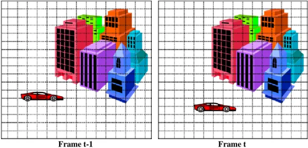
Frame t-1 Frame t
Figure 3.1 Adjacent frames from any video.
A video occur from animation and voices. These animation and voices can change in each time on video. A picture in any time on video is called frame. Video has more than one adjacent frame. In each time, the video frames either can be change or not. The only difference between one frame and another is the result of either the camera moving or an object in the frame moving. In figure 3.1, there is a motion the car is driven, on the other hand the buildings are in the same place in each frame. So, we can split each video into frames according to time.
8
4.
VIDEO CODEC, BITSTREAM, TRANSPORT
4.1. VIDEO CODECS
Codec is compression algorithm software that is used to compress or decompress a digital media file such as video to reduce the size of a stream. The compression is lossy because when the video is coded take some part from the original file and discarding other parts of the video to reduce the size of the video. The codec decides what data take part in compressed version, what are not with translator. Each codec does not use the same way to translate the video file so we must use the same codec either encode or decode. We must choose the best codec for what we are trying to do in order to maintain the best ratio of the file size to quality.
The codec have two main parts encode and decode. To compress the video encoder performs the encoding function to decompress the video decoder performs the decoding function to get video frames. There are different video codecs; some of them include both encode and decode part, some codecs only include whether encode or decode part. For instance, when we open any video file from CD, player use the video codec to decompress the file so the video can be played.
There are different video codecs which are use different file format. We will compare two codecs that are H.264 and VP8.
4.1.1. H.264
H.264 is known as MPEG-4 Part 10 or AVC (Advanced Video Coding) that is lossless video codec. Encoder part of it uses x264 which is only encoder and a GPL licensed implementation of the H.264 video standard, decoder part uses FFmpeg decoder. It is most commonly used and known video compression standard, and also it is used by streaming internet sources such as videos from Vimeo and Youtube.
The main function of this standard is high compression and quality for broadcasting. This standard gives answer to solve technical solution in the following application areas
9
• Interactive or serial storage on optical and magnetic devices, DVD, etc.
• Conversational services over ISDN, Ethernet, LAN, DSL, wireless and mobile networks, modems, etc.
• Video-on-demand or multimedia streaming services over ISDN, cable modem, DSL, LAN, wireless networking, etc.
• Multimedia messaging services (MMS) over ISDN, DSL, Ethernet, LAN, wireless and mobile networks, etc.(Wiegand et al., 2003).
The features of H.264 (Robertson; Richardson)
• It provides good video quality with lower bitrate than previous standards.
• It allows using in wide area applications on variety of networks and systems.
• It is using multi-picture inter-picture prediction that provides improvement in bit rate and quality in scene.
• It supports variable block-size motion compensation (VBSMC) with 16x16 large block size and 4x4 small block size.
• This standard enables quarter-sample-accurate motion compensation.
• It uses multiple reference pictures for motion compensation that means more than one previous picture to predict the values in an incoming picture. • Encoder weighted the motion compensated prediction signal to improve coding efficiency for scene containing fades.
• Dependency between the ordering of pictures for motion compensation and ordering picture for display is largely removed with this standard.
• It support sample depth precision ranging from 8 to 14 bits per sample.
• It is more convenient for video network delivery and delivery of HD, high definition video.
10
• Entropy coding part includes context-adaptive binary arithmetic coding (CABAC), Context-adaptive binary-length coding (CAVLC) and variable length coding (VCL).
• It use in loop deblocking filter which support to prevent blocking artifacts.
• It uses discrete cosine transform (DCT) and Hadamard transform.
• It is available for everyone to implement.
4.1.2. VP8
VP8, which is developed by Google, is kind of video compression format. It has software library capable of encoding video streams that is libvpx. Libvpx is not only encoder but also decoder because it is capable of decoding VP8 video streams. There are another decoder is ffvp8 decoder is faster than libvpx decoder (Garrett-Glaser, 23/07/2010).
The features of VP8
• Compiled with VP8 library
• It includes most color space conversions supported by Xvid codec
• Uses several threads on multi-core processors.
• It encode file with libvpx and decode file not only with libvpx but also ffvp8
• Firefox, Chrome, Opera and Adobe support VP8.
• Solves the HTML5 video problem.
Comparison H.264 with VP8 (Ozer, 2010)
Both of them are free. When we compare the feature on implementation H.264 has advantages than VP8. So H.264 not only is more efficient but also has slight quality advantage. H.264 is supported by iDevices (with CPU), Blackberry, Palm, Android (with CPU acceleration). Compression style of H.264 is both lossy and lossless; compression style of VP8 is only lossy. In conclusion, VP8 is a great codec but H.264 has superior integration in streaming and device world.
11 4.2. BITSTREAM
It is sequence of bits and set of headers allow simple access to binary structures such as MPREG, DVB, IEFT, etc.
4.2.1. MP4
MP4 ("MPEG-4 Part 14," 2004) is known as MPEG-4 which is digital multimedia format to store video and audio. This format allows streaming over the Internet like other format. The file extension is .mp4.
4.2.2. WebM
WebM is an open media file format designed for the web and it file consists VP8 video codec and file compressed Vorbis audio streams ("About WebM,"). Youtube, Wikimedia, Skype uses WebM for HTML5 player. It has simple container format and minimal encode with sub-option and satisfy highest quality real-time video transmit. The file extension is .webm.
4.2.3. ASF
ASF ("Advanced Systems Format,") is part of the Windows Media framework so it is Microsoft’s digital video container format for streaming media. .asf, .wma, .wmv are the file extension of ASF. It determines the structure of the video / audio stream instead of how the video or audio should be encoded.
4.3. TRANSPORT WITH A NETWORK PROTOCOL
The most important part of the video streaming is transport encoded video file to target node or all neighbor of sender node. After encoding the video stream, we need to transport this stream with any network protocol. According to your application, you can choose any protocol such as UDP, RTP, and TCP.
4.3.1. User Datagram Protocol (UDP)
UDP is unreliable and connectionless communication protocol that is used for transport of data across an internet protocol based network. UDP does not need to connection when send data. It uses to transmit real time data transport like voice and video in wide area network (WAN). The time of data transfer is little because it is not
12
deal with connection, retransmit data and flow control. DNS, TFTP and SNMP use UDP that does not need to more bandwidth.
UDP is not reliable protocol because it sent packet in network but it does not control the packet is received or not to target node and it have not approve the packet is received or not. Also it does not check the reliability of the packet and take all packets to its system so it is not convenient to security of the system. If the time is more important for your system you can use UDP because it is not waiting acknowledge from target. The quality of real-time data transfer of UDP is less than TCP because UDP and TCP use the same network path and TCP has more data transfer than UDP.
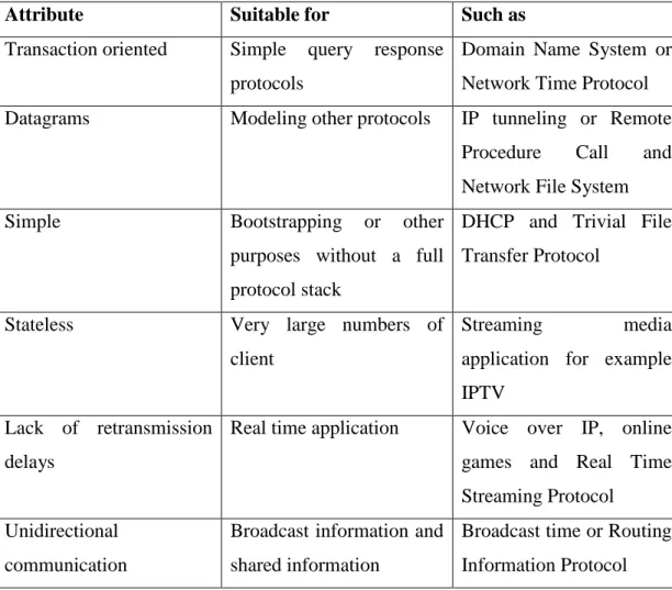
According your application, you can choose UDP to transmit packet because some properties of the UDP. In table1, there are some features of the UDP and in which situation it used for transmission.
Table 4.1 UDP’s attributes and suitable application
Attribute Suitable for Such as
Transaction oriented Simple query response protocols
Domain Name System or Network Time Protocol Datagrams Modeling other protocols IP tunneling or Remote
Procedure Call and Network File System
Simple Bootstrapping or other
purposes without a full protocol stack
DHCP and Trivial File Transfer Protocol
Stateless Very large numbers of
client
Streaming media
application for example IPTV
Lack of retransmission delays
Real time application Voice over IP, online games and Real Time Streaming Protocol
Unidirectional communication
Broadcast information and shared information
Broadcast time or Routing Information Protocol
13 Packet Structure
In figure 4.1 illustrate packet structure of the UDP. UDP header has four parts; source port, destination port, length, and checksum, size of them are equal 16 bit. Source port is not used for each transfer, when the packet is received to destination port, sometimes it need to reply the packet is received or not according to application. Source port is optional both IPv4 and IPv6, checksum is optional in IPv4 only. Destination port include where data packet will be transmitted. Length part stores the length of the entire datagram which includes header and data. Checksum field is for checking any error of the header and data. If there is no any checksum, the field value fills with zeros. There are difference between IPv4 and IPv6 calculation of the checksum. UDP has checksum for data integrity and port numbers for transmit datagram from source to destination. Data field contains the actual data.
Figure 4.1 UDP Header
4.3.2. Real-Time Transport Protocol (RTP)
RTP is widely used in communication and entertainment systems and these systems involve streaming media such as television services web-based push-to-talk, telephony and video conference applications. RTP is send real-time audio, video or simulation packets from source to destination over IP networks. It provides end to end delivery services for data with real time properties (H. Schulzrinne, Casner, Frederick, & Jacobson, January 1996).
RTP has connection between source and destination during data transfer. Machine starts to communicate with this connection. For each different media type machine has different connection. RTP sets up for each stream.
RTP when is transferring media stream such as audio and video usually uses with RTP Control Protocol (RTCP) that is used to follow transmission statistic and quality of services (Qos) information. RTP is unidirectional, RTCP is bidirectional. RTP framing if needed identify synchronization source, transfer media data (unreliable),
14
demultiplexing (combined audio and video), synchronization and sequencing support, next layer (e.g. media) identification (H. Schulzrinne, December 1992). RTCP identify participants, describe content, quality of services information, request for retransmission (H. Schulzrinne, December 1992).
Packet Structure
Figure 4.2 shows the RTP packet header information. Version stores 2 bits information about the version of the protocol. P represents padding which determines if there are extra padding bytes at the end of the RTP packet. X is the extension header between standard header and payload data. CC is the short term of the CSRC Count which is contains number of CSRC identifiers. M is marker of the application level. PT is payload type that determines the format of payload and its interpretation. Sequence number store incremental value when the packet is received to target, it is important when the packet is loss and restore packet sequence. SSRC is synchronization source which identify the source of a stream. CSRC is contributing sources which ones generated from multiple sources. Extension header part is optional, first part of it store profile specific identifier, second part is extension header length.
Figure 4.2 RTP header
4.3.3. Transmission Control Protocol (TCP)
TCP is a reliable, error checked delivery of stream, connection-based, and host-to-host protocol. Most of the data transfer on the internet makes over TCP because it ensures to deliver the data to target node. HTTP, HTTPS, POP3, STM and FTP are the most popular protocols transfer the data via TCP. The most popular protocol uses TCP because of the characteristic features of the TCP;
Stream Data Transfer: TCP gives a sequence number to an unstructured stream of bytes. TCP must be packed the byte streams to packet to satisfy the communication between sender and receiver. Then TCP sends this packet to IP layer to transfer to
15
the destination machine. Application does not have divide data to blocks because TCP decides how to segment the data and forward due to own convenience of the data.
Reliability: TCP gives a sequence number for each byte of data. When the TCP sends any data, it follows the order of the data from its sequence number. After sending data, TCP waits for acknowledge from destination port until timeout. When the destination host sends ACK with sequence number, sender understands this data is received by destination. If acknowledge did not come, sender transmits data again until it takes ACK. According to this ACK, TCP does not send any segment again if it is received. So, TCP is reliable and eliminates duplicate segments.
Flow Control: Sometimes sender sends more fast data to receiver. If the receiver has not enough places to take this data, it stores data to the buffer. After some times, memory of the buffer will be full and the receiver does not take data any more. Some packet cannot reach to receiver so the sender will send these packets again and again. This situation will affect the performance of the communication. To avoid from this situation, TCP uses flow control. If the received computer took more data than its capacity of the data received and it has not enough memory buffers to store this data, it will send “Not ready” alert message to sender with flow control mechanism. Sender stops sending data until received computer sends “Ready” message.
Multiplexing: TCP uses the IP addresses or port number to communicate each other over Internets. Socket consists network and host addresses and uses for each TCP connection. A socket may be simultaneously used in multiple connections (Information Sciences Institute University of Southern California, September 1981).
Connections: Connection contains sockets, sequence numbers and window sizes information. Two hosts must be established connection before starting communication. The connection is terminated or closed after communication is finished.
16
Precedence and Security: Each machine may specify precedence and security of their communication. According the importance of the stream, TCP sent data streams.
Full duplex: TCP can send and receive data streams simultaneously.
TCP is connection oriented services so to transfer data among network first must be open a connection on host, then host can send any data to another until connection is open. TCP working flow chart illustrated in figure 4.4 in detail. TCP is operated in three main parts; (i) start connection, (ii) data transfer, (iii) finish connection. Before start data transfer, connection must be established in handshaking process. After all data is transferred, the connection is closed and all allocated resources are released.
Table 4.2 Terminology of TCP state diagram in figure 4.4.
STATE ACTION
CLOSED Both server and client have no connection. LISTEN Server waiting for a connection request
SYN-RCVD Server waiting for a confirming connection request SYN-SENT Client sent connection request to server
ESTABLISHED The connection is open both server and client to data transmission.
FIN-WAIT-1 Both server and client waiting for connection termination request.
FIN-WAIT-2 Both server and client waiting for connection termination request.
TIME-WAIT Either server or client waiting for enough time to transfer the packet to destination and acknowledge.
CLOSING Both server and client waiting for connection termination request acknowledge from the remote TCP.
CLOSE-WAIT Both server and client waiting for a connection termination request from the local user.
LAST-ACK Both server and client waiting for an acknowledge of the connection termination request previously sent to the remote TCP.
17
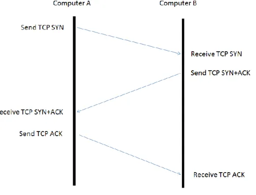
Before starting the data transfer connection must be between two computers. Assume that computer A wants to send data to computer B, first computer A sends TCP-SYN message to computer B. When the message received to computer B, computer B sends acknowledge message TCP SYN+ACK to computer A. Then computer A sends acknowledge (ACK) message to computer B. Finally, computer B takes acknowledge (ACK) message which is means TCP connection is established. The TCP connection is setting up between to computers and it is called three-way handshake (Figure 4.3).
Figure 4.3 Three-way handshake
Now computer B received packets from computer A after connection is started. Computer B replies to computer A for each received packet. According to this information, computer A makes decision which packet it must be send to computer B. If any packet is loss, it sends to computer B again until all packets are received by computer A correctly. TCP uses sliding window concept when send data to destination port. Sliding window contains specific size of data start to send, after each acknowledges windows choose another data which has not sent yet from the data sequence.
18 Figure 4.4 TCP state diagram (Zaghal & Khan, 2005)
After finish data transfer, one of the computers which have TCP connection sends finish message to other. For example, computer A sends TCP FIN message to computer B to finish the connection. Computer B replies with TCP ACK message and send TCP FIN to computer A. Computer A replies TCP ACK to computer B. thus, the connection is closed between computer A and B, it is called four-way handshake (Figure 4.5).
19 Figure 4.5 Four-way handshake
Packet Structure
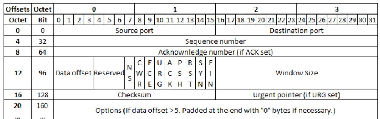
Two computers must be TCP connection to communicate each other. TCP separates the data in data stream and adds header to create TCP segment. Each TCP segment is encapsulated into an internet protocol (IP) datagram to transmit data over network. Each TCP segment includes segment header and data section. Header part, which contains ten mandatory fields, illustrates in figure 4.6 and data section comes after header. Source port stores the TCP port information of sender computer. Destination port stores the TCP port information of the target computer. TCP gives number for each segment of the data and it stores this information in sequence number. When the target node take the packet, the acknowledge message is sending with acknowledge number. If the ACK bit is set this field contains the value of the next sequence number the sender of the segment is expecting to receive (Information Sciences Institute University of Southern California, September 1981). Data offset determine the size of the TCP header. Reserved is keeping to use in the future. After reserved part, there are code bits or flags part that is about control information of the segment. Each of them has 1 bit size in TCP header. Control bits from left to right:
• Nonce Sum (NS): This field is optional and added to ECN to protect against concealment of marked packets from the TCP sender.
20
• Congestion Window Reduced (CWR) is set when the TCP segment is received from sender host ECE flag set and had responded in congestion control mechanism.
• ECE: Echo indicates
• Urgent Pointer (URG) shows that urgent pointer field is important.
• Acknowledgement (ACK) shows that acknowledgement field is important.
• Push Function (PSH) asks to push the buffered data to the receiving application.
• Reset the Connection (RST): When the sender is abort the connection this part signals the receiver to reset the connection.
• Synchronize (SYN): The sender embarks to synchronize sequence numbers when the field is set.
• No more data from sender (FIN): When the receiver and sender finish the byte stream for current TCP connection, this field is set.
Window size store the size of the segment that is sending is current willing to receive. Checksum part checks the segment is received correctly or not. TCP can runs over IPv4 and IPv6, the checksum computation will be different according to IP address’ type. Urgent pointer is used when the data must be sent urgently. Options part generally store the maximum size of the TCP segment.
21 TCP/IP
TCP provides reliable and in order transfer on IP which is unreliable services. TCP includes ACK and timer to satisfy the reliability. It approves when the packet is received, but it sends packet again when the packet is loss (Kurose & Ross, 2003). TCP can use Fast Retransmit algorithm to send missing packet unless timeout expires. If the same ACK information is sent in three times that packet sends again in this algorithm (W. Stevens, January 1997). TCP uses sequence number to determine loss packet and same packet which are transmitted. TCP can send more than one packet at the same time with pipeline method. To determine the packet number this will send as using flow control and congestion control. Flow control specifies how many packets the receiver will be accept, congestion control specifies how many packets the sender delivers according to bandwidth. Then choose the minimum packet number to transmit (W. R. Stevens, 1994). This packet number represents as window size.
Comparison UDP with TCP
There are a lot of difference between UDP and TCP which is given in table 4.3 so properties of TCP are much better than UDP to transfer video data. The most common similarity is both of them have source port, destination port and checksum fields in header structures.
22 Table 4.3 Differences TCP and UDP
TCP UDP
Stream-oriented Datagram-oriented
Connection-oriented Connectionless
Reliable delivery Unreliable delivery
Provide flow control Does not provide flow control
Has order for data packets (Sequencing of data)
Has no inherent order (No sequencing of data)
Absolute guarantee that data will send correctly without lossy in the same order.
There is no guarantee for data transfer.
Header size 20 bytes Header size 8 bytes
Sends acknowledge No acknowledgement
Heavyweight Lightweight
Retransmission of lost packets. No retransmission of lost packets Slow because of error checking mechanism Faster, simpler and more efficient
23
5.
VIDEO STREAMING
Video streaming is multimedia streaming media that sends the content in compressed form over the internet to the end user and the content are displayed by the viewer in real time. The end users do not have to wait to download the entire video file to play it. The media sends the content in a continuous stream and it can be played when it arrives. The compression of the media can be with any video codec. The video stream is compressed using a video codes such as H.264 or VP8. Encoded video streams are assembled in a container bitstream such as MP4, FLV, WebM, ASF or ISMA. The video stream can be transport with a network protocol such as UDP, RTP or TCP.
In figure 5.1 shows the work principle of the streaming on video. Streaming technique used for transferring large multimedia files quickly without downloading entire file. With video streaming the client browser can start downloading the data before the entire file has been transmitted.
Figure 5.1 Video Streaming
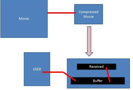
Example 1: Assume that in figure 5.1 the big blue square is movie which the user wants to watch on internet. The size of the movie is very big to download entire without any interruption. We need to use codec to make movie smaller. So, the codec
24
compresses the movie and this compressed movie transmitted to target. When the data received, the application is processing data and converting it to sound and picture to get video and this data stored in buffer. If streaming client receives the data more quickly than required, it needs to save the excess data in a buffer. If the data does not come quickly enough, the presentation of the data will not be smooth. While user watching the movie, buffer continuously sends these data to user. If everything works correctly, which is means that there is always extra data in the buffer, it was signing is everything live from the user perspective.
There are a lot of online web streaming activities. These web applications provide the user whether they want to watch video, news recaps, TV shows, tutorials or funny videos and user can watch video in any time without downloading all video file. The most popular websites are youtube.com, vimeo.com, metacafe.com, hulu.com, veoh.com which provide videos to their user with streaming. When we look this web page, there are some advantages and disadvantages part of them.
1. Youtube.com
It is the most popular video streaming website which offers the all user to submit and watch thousands of video in different topic freely. The advantages of Youtube are high quality video playback; support almost all video formats, offer 16:9 aspect ratio. The disadvantages of it are to limit video access and the video limit of 100MB.
2. Vimeo.com
This website allows the user to upload up to 500MB of video content per week. It supports full HD streaming and widescreen format and also it is suitable to watch and share high-quality and HD personal video because of a wide array of video codec support. On the other hand, convert a single video takes over an hour because it is used to upload large movie files.
3. Metacafe.com
This website duplicate videos from Youtube, but there is a wide array of video tutorials on many subjects such as magic and science experiments. This tutorials
25
is high-quality but the video resolution is high and videos are pixelated due to up-sampling
4. Hulu.com
Hulu which offers a wide array of free TV shows legally, videos can be viewed in 360p for slower Internet connections. But high definition video streaming is not available for most videos.
5. Veoh.com
Veoh offers TV shows for free and the video stream in higher quality resolution.
In generally, this video transmission process presents some advantages and disadvantages.
Advantages of the video streaming: • Minimal Wait
• Instant viewing
• No long download times
• Do not have to waste memory space on hard drive
• Use specific bandwidths
• More security of content publishing
• Professional Training
• Education
Disadvantages of video streaming: • Slow playback
• Possible start/stop of video if connection is not good
• Copyright issues
26
• Quality depends on number of people also using the video
• Bandwidth
• Cost
5.1. Video streaming technologies
There are different technologies for streaming video over the internet. Some of them are data- independent, the others are data-independent.
5.1.1. Data-independent delivery technologies 5.1.1.1. Automatic Repeat request (ARQ)
ARQ is suitable only for point-to-point needs feedback, and added delay arbitrarily large (Vitali, October 2007). If the data losses appear time to time, this technology is convenient to send packet successfully only once. If the data loses frequently, data retransmits. The receiver always sends ACK to sender. If the ACK is not received, sender wait limited time then sends data again. When the receiver replies ACK as “the data is received wrongly”, the wrong part is sent again.
5.1.1.2. Forward Error Correction (FEC) / Erasure Recovery
FEC or channel coding is a digital signal processing technique used for errors in data transmission over unreliable or noisy communication channels. FEC is no feedback required, all-or-nothing performance, waste of capacity when tuned for worst case, complexity, significant added delay (Vitali, October 2007). Sender uses error-correction code (ECC) and encodes message in a redundant way. Redundancy satisfies the receiver to detect and correct the errors without retransmission. FEC uses redundant bit which is added parts of the data again when transmits message to receiver. This information may be or not seen in encoded output. When the losses are too much, added redundancy is not enough and losses are not recovery. In this situation, the final video decoded quality will be very bad. The losses are very important to recover the video packets with redundancy. Encoding and decoding of redundant packets need memory and computational power so the complexity can be very high (Vitali, October 2007).
27 5.1.2. Data-dependent delivery technologies
5.1.2.1. Robust source coding
There are different techniques to aim robust source coding. When we encode the video packet, the importance of the packet is related with more efficient video encoder. Also the loss of packet is related with compression efficiency. If the compression efficiency is high, the loss of packet has destructive effect. Vice versa the loss of packet has slight effect (Vitali, October 2007). Prediction, transform, quantization, and entropy coding techniques are used for more efficient encoding. After efficient squeeze the video, video must be sent it to neighbors. Transmission can affect robustness because of transmission delay.
5.1.2.2. Layered Coding (LC)
It is similar to Multiple Description Coding. But there is difference between two coding such as dependency. LC entails prioritization and recovery mechanism, allows efficient scalability (Vitali, October 2007). LC has two layers; one base layer and several enhancement layers. Enhancement layers can use after one another to improve the decoded quality of the base layer. If it is necessary, layers can be dropped but not base layer. Enhancement layer can be drop, last enhancement is dropped first. Each layer has different importance on decoding; the most important one is based layer. So the recovery mechanism needs to guarantee to transmit at least base layer.
5.1.2.3. Multiple Description Coding (MDC)
Multiple description coding (Goyal, 2001) is a kind of data transmission coding method which is used to enhance the error resilience. It is very robust and the quality very good even at high loss rates.
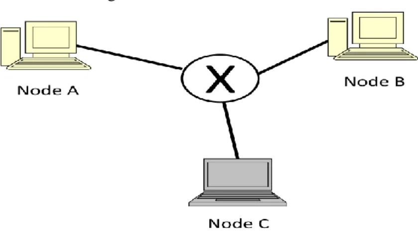
Assume that a packet must be send to all nodes (A, B, C) on network is shown in figure 5.2. First the source is encoded by any encoder which is lossy. Packet is created to send all receivers. Then packet is sent and to guarantee the packet received the all node send more than one the packet. When the packet reaches any receiver more than one time, it is not advantages. When the packet is not received the packet is lost and this node never will be get. This is simple scenario to send any packet. On
28
the other hand, the source can divide and all packets are not same. In this scenario more received packet mean more quality of the source. The second scenario satisfies with MD coding.
Figure 5.2 An example of network
MD separates a single media stream two or more independent sub parts, each of them are called description. All description is individually packetized and sends either same or separate channels. Description has more contributions such as spatial or temporal resolution, signal to noise ratio, and frequency content when packet transmits. Description can be either same or different priority.
MD is an important coding because it provides high video quality even the any of the packet lost when transmission and the packet is not retransmitted. MD generally is used in real time interactive application such as video conferencing which is not possible to retransmit packets. It can be preferred in simple network which has no feedback and is need retransmission.
When we send a picture, first encodes picture with multiple description coding. For example, to create description we divide picture both horizontally and vertically to get four descriptions (Figure 5.3). These descriptions can be sent in either same or different channels. If there is no any loss, the picture will be decoded correctly. If there are any lossy packets, MD coding can be fixed the picture with motion compensation. The missing part can be predicted and fixed according to neighbor pixels. Motion compensation also satisfies integrity between each frames of the video.
29
Figure 5.3 Preprocessing stage of MDC in picture.
MDC is more robustness and scability. If there is any corruption the sequence of the descriptions, it can be reconstructed with other received packets. Thus, the user does not notice the corruption in picture or video. MDC overwhelms limited bandwidth and packet loss.
MDC is used most commonly in packet networks, distributed storage, frequency hopping wireless systems, hybrid digital broadcast.
In (Vitali, October 2007) mentions about that there are three different compression algorithms to transmit the same picture. These three source codes respectively non-progressive, progressive and multiple description. First two algorithms use retransmission protocol, MD is not. Assume that there is software which send packet in specific time slot. This software starts to send packet to receivers. One of the packets is lost for example the third one. In this situation first two algorithms will be retransmit packet until it is received. On the other hand, MD will be lost the packet because it is not use retransmission protocol. Packet received time will be increase because of retransmission for the first two algorithm. In first two algorithms, the packet will be received to target node despite long time. On the contrary, MD coding recovers the lost part unless the packet is never received and the picture will have minimum aircraft. As a result, if there is no lossy packet, progressive code gives the best picture quality. But, MD has the best quality and is very fast when the packet is lost.
30
6.
MULTI-STATE VIDEO CODING
There are different video coding techniques and standards to improve video quality. One of them is Multi-State Video Coding. Multi-State Video Coding is a multiple description scheme where the video is split into two or more subsequences.
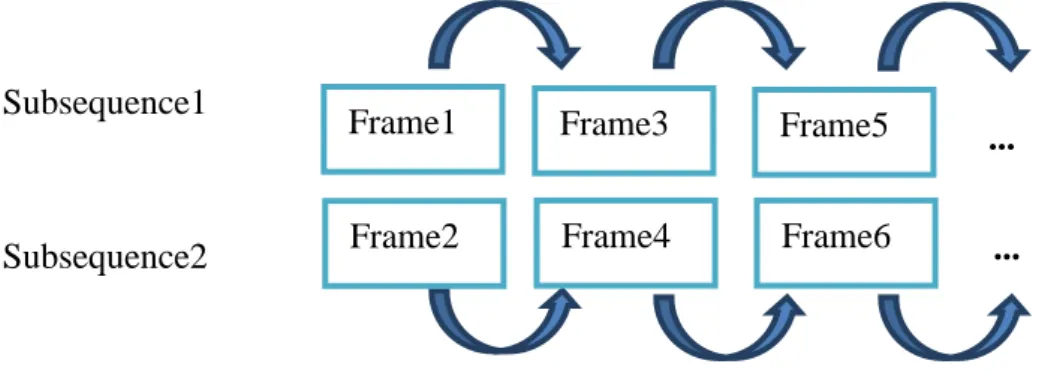
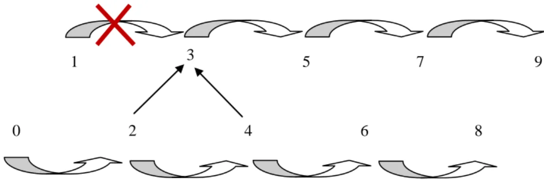
Subsequence1
Subsequence2
Figure 6.1 Subsequences of video in MSVC.
Why is it important?
Assume that, we have K packets to send the destination address. We give a number for each packets start from 1 to K. In a progressive transmission, the quality depends the number of successive packets received, starting from first packet, increases. If the packets are sent and received without loss, the progressive transmission works well. On the other hand, the sequences of the packet transmission will be changed if a packet is loss. The sequences of the packet are important when we sent a video to destination address. If there is any loss packet, not only the quality of the video will be decrease but also the transmission will be delayed.
With MSVC, we can separate video to more than one subsequences; the first subsequence is include odd numbered frames, the second subsequence is include even numbered frames like Figure 6.1. Each subsequence is encoded and transmitted separately and can be decoded independently. Thus, error resilience of the system increases because reconstruction of the video is well even there are some loss frames. The lost frames in one subsequence are reconstructed by using state recovery such as interpolation. Frame1 Frame2 Frame3 Frame4 Frame5 Frame6 ... ...
31
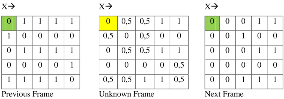
Interpolation is a numerical analysis method of construct a new data point within the range of a discrete set of known data points. In this scenario, each pixel value in each video frames is discrete set of data points. These points are known, the loss frames pixel values is unknown data point. This method used the previous and the last frames from other subsequence to generate loss frame with using (6.1).
In formula (6.1), if the xa and xb is equal, the formula will be
We will use (6.2) formula, because we try to find unknown value same location with previous and next frame. To find the first point from unknown frame, we apply (6.2) and find result 0 (zero) as shown in Figure 6.2.
X 0 1 1 1 1 1 0 0 0 0 0 1 1 1 1 0 0 0 0 1 1 1 1 1 0 Previous Frame X 0 0,5 0,5 1 1 0,5 0 0,5 0 0 0 0,5 0,5 1 1 0 0 0 0 0,5 0,5 0,5 1 1 0,5 Unknown Frame X 0 0 0 1 1 0 0 1 0 0 0 0 0 1 1 0 0 0 0 0 0 0 1 1 1 Next Frame
Figure 6.2 Using Interpolation in video frame to find values of the unknown frame.
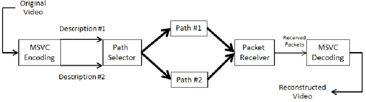
A MSVC system (Figure 6.3) has two main components: multiple state encoding & decoding and path diversity transmission (Flierl & Sikora, 2005). Encoded part generates transmission packets for each subsequences, decoded part generates frames from receiver packets. Path diversity transmission part is related with transmission of each encoded packet to the destination address separately. After system generates the unknown frames of the video, system merges frames to create reconstructed video.