Enhanced transmission through a subwavelength aperture using metamaterials
Atilla Ozgur Cakmak, Koray Aydin, Evrim Colak, Zhaofeng Li, Filiberto Bilotti, Lucio Vegni, and Ekmel Ozbay
Citation: Appl. Phys. Lett. 95, 052103 (2009); doi: 10.1063/1.3195074 View online: https://doi.org/10.1063/1.3195074
View Table of Contents: http://aip.scitation.org/toc/apl/95/5
Published by the American Institute of Physics
Articles you may be interested in
Gratingless enhanced microwave transmission through a subwavelength aperture in a thick metal plate
Applied Physics Letters 81, 4661 (2002); 10.1063/1.1527704
Sensing with toroidal metamaterial
Applied Physics Letters 110, 121108 (2017); 10.1063/1.4978672
Ultra-thin metasurface microwave flat lens for broadband applications
Applied Physics Letters 110, 224101 (2017); 10.1063/1.4984219
Ultra-broadband microwave metamaterial absorber
Applied Physics Letters 100, 103506 (2012); 10.1063/1.3692178
Split ring resonator sensors for infrared detection of single molecular monolayers
Applied Physics Letters 95, 043113 (2009); 10.1063/1.3194154
Subwavelength resolution with a negative-index metamaterial superlens
Enhanced transmission through a subwavelength aperture using
metamaterials
Atilla Ozgur Cakmak,1,a兲Koray Aydin,1,2Evrim Colak,1Zhaofeng Li,1Filiberto Bilotti,3 Lucio Vegni,3and Ekmel Ozbay1
1
Department of Electrical and Electronics Engineering, Nanotechnology Research Center and Department of Physics, Bilkent University, 06800 Ankara, Turkey
2
Thomas J. Watson Laboratories of Applied Physics, California Institute of Technology, Pasadena, California 91125, USA
3
Department of Applied Electronics, University of Roma Tre, 00146 Rome, Italy
共Received 18 February 2009; accepted 15 July 2009; published online 4 August 2009兲
We report an enhanced transmission through a single circular subwavelength aperture that is incorporated with a split ring resonator共SRR兲 at the microwave regime. Transmission enhancement factors as high as 530 were observed in the experiments when the SRR was located in front of the aperture in order to efficiently couple the electric field component of the incident electromagnetic wave at SRR’s electrical resonance frequency. The experimental results were supported by numerical analyses. The physical origin of the transmission enhancement phenomenon was discussed by examining the induced surface currents on the structures. © 2009 American Institute of Physics.关DOI:10.1063/1.3195074兴
The interest in transmission through subwavelength ap-ertures has recently rapidly increased.1,2 The topic was ad-dressed during the 1940s, where Bethe3put forward his the-oretical analysis suggesting relatively poor transmission figures at the output side of a subwavelength aperture. The problem remained a major challenge until the pioneering work of Ebbesen et al.4 From that moment on, the main focus has been shifted to elucidate the enhancement mecha-nism for subwavelength apertures.5Researchers have set out to identify the role of the surface plasmons and to offer physical explanations for the transmission enhancement phenomenon.6,7 Methods have been sought to effectively guide the incoming electromagnetic共EM兲 wave into the sub-wavelength aperture that will in return result in enhanced transmission. A slightly different approach was adapted in a paper by Alu et al.,8in which a matematerial cover over the aperture was theoretically shown to produce enhanced direc-tional transmission by minimizing the diffraction losses. On the other hand, split ring resonators 共SRRs兲 had already gained a well-established background in the metamaterial community.9 Innovative models were developed for SRRs that were placed inside a small circular metallic aperture.10 Subsequently, Aydin et al.11proposed in a rather recent work an alternative method for transmission enhancement by put-ting a SRR in front of a subwavelength aperture.
We present here a more detailed analysis of the enhanced transmission process by focusing on an electrically coupled SRR that was made to cooperate with a subwavelength ap-erture. The resonator nature of the SRR was exploited to concentrate the fields in the vicinity of a subwavelength ap-erture to facilitate considerable improvement in the transmis-sion factors at microwave frequencies. Besides, the depen-dence of the resonance frequency of the SRRs on the enhanced transmission was studied by employing three dif-ferent SRRs in the simulations and experiments. Induced
sur-face currents were calculated in order to discuss the enhance-ment mechanism. The transmission improveenhance-ment figures were obtained as a function of various aperture radii.
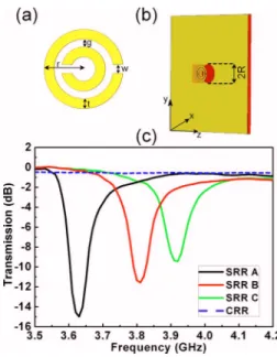
Three distinct SRR designs with the labeled dimensions, which are shown in Fig.1共a兲, were used. SRRs are deposited on a dielectric printed circuit board 共PCB兲 with a thickness of 1.6 mm and a dielectric constant of=3.85. The deposited copper thickness is 30 m. Samples A, B, and C have split widths of wA= 0.2 mm, wB= 0.4 mm, and wC= 0.6 mm. A
closed ring resonator共CRR兲 was obtained by shortening the split of sample A. Each one of the CRR and SRRs possesses
a兲Author to whom correspondence should be addressed. Electronic mail:
FIG. 1. 共Color online兲 共a兲 The SRR configuration and the labeled SRR design dimensions: split width共w兲, the distance between the inner and outer rings 共g=0.2 mm兲, the metal width 共t=0.9 mm兲, and the outer radius 共r=3.6 mm兲. 共b兲 The experimental setup: SRR is attached to the aperture with a diameter of 2R. SRR is shifted by an amount of R共in the −z direc-tion兲 with respect to the aperture. 共c兲 Measured transmission results for sample SRR A共solid black line兲, B 共solid red line兲, C 共solid green line兲, and the CRR共dashed blue line兲.
APPLIED PHYSICS LETTERS 95, 052103共2009兲
a supporting PCB of 8⫻8 mm2. An aperture with a radius of R = 4 mm was prepared by etching the copper on a single side copper-coated separate PCB关Fig.1共b兲兴. The metal side of the resonators was affixed to the metal side of the PCB. There was a separation distance of approximately 0.1 mm between the two metal faces. Conventional waveguide anten-nas were connected to the Agilent N5230A network analyzer to collect the transmission results. The transmission charac-teristics of the SRR samples are depicted in Fig. 1共c兲. The incident beam had an electric field component along the y axis关see Fig.1共b兲for directions兴. The electrical resonance of the single SRRs was observed when the SRR plane was per-pendicular to the propagation of the incident beam. The elec-trical resonance frequencies of samples A, B, and C were found at 3.63, 3.81, and 3.92 GHz, respectively.
Then, the transmission spectrum was acquired for the aperture 关black line in Fig.2共a兲兴. Since the aperture is too small in comparison to the wavelength of operation, we wit-nessed low transmission figures.3 However, a peak in the transmission spectrum around 3.7 GHz was spotted once sample A was placed in the near field of the aperture关solid green line in Fig. 2共a兲兴. The experiment was repeated by replacing sample A with the CRR. CST Microwave Studio was used in order to realize the same configurations in the simulation environment. The results are illustrated in Fig.
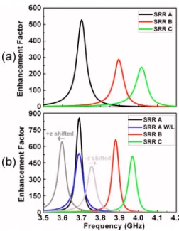
2共b兲, which show the good agreement between the simula-tion and experimental outcomes. Figure2points out that the increase in the transmission figures was caused by effectively coupling the electric field component of the incoming field to the SRR structure. Sample A, which already had an electrical resonance around 3.63 GHz, triggered an enhanced transmis-sion at 3.7 GHz. The absence of an electrical resonance for the CRR configuration prevented an extraordinary transmis-sion within the same frequency band. Figure 3 exhibits the experimental and simulation based enhancement factors in linear scale when the same procedures were followed for samples B and C. The transmission peaks occurred at 3.7 共sample A兲, 3.89 共sample B兲, and 4.01 GHz 共sample C兲, which coincide well with the electrical resonances of the
SRRs. Moreover, the measurements with the SRR-attached aperture yielded remarkable transmission improvement fac-tors as high as 530, 288, and 232 for samples A, B, and C, respectively. Originally, the losses were not added to the cal-culations. The losses dropped the numerically computed en-hancement factor to 540 from 856 for sample A 关see Fig.
3共b兲兴 while broadening the enhancement peak when the met-als are modeled with copper and the dielectrics with a loss tangent of ␦= 0.01. The precise location of the SRR with respect to the aperture severely influences the transmission enhancement frequency. The enhancement turned out to be located at 3.59 and 3.75 GHz when sample A is misaligned by 0.3 and ⫺0.1 mm, respectively, from the origin of the aperture along the z axis 关solid gray and light gray lines in Fig.3共b兲兴.
The effect of the aperture radius on the enhancement factors was considered in Fig. 4. As the aperture radius ranged from 2.4 to 7 mm, the simulation results showed that the transmission enhancement frequencies were also altered
FIG. 2. 共Color online兲 共a兲 Experimental and 共b兲 simulation results of the transmission spectra: aperture only 共solid black line兲, aperture with CRR 共solid red line兲, and aperture with sample SRR A 共solid green line兲.
FIG. 3. 共Color online兲 共a兲 Experimental and 共b兲 numerical analysis of the enhancement figures for three different samples. Sample SRR A共solid black line兲, B 共solid red line兲, and C 共solid green line兲. Sample SRR A with the losses共solid blue line兲. Sample SRR A is shifted ⫺0.1 mm 共solid light gray line兲 and 0.4 mm 共solid gray line兲 in the z direction with respect to origin of the aperture. The losses are also taken into account during the shifting procedure.
FIG. 4. 共Color online兲 STE factor for various aperture radii, in the range of 2.4–7 mm. Numerical results 共black dots兲, experimental results 共blue tri-angles兲, and a polynomial fit curve for the numerical results 共solid red curve兲. Inset: Calculated transmission enhancement frequencies correspond-ing to different aperture sizes.
although the same SRR 共sample A兲 and was employed throughout the entire analyses 共see Fig. 4 inset兲. The EM
response of the combined system, the aperture together with the SRR, had to be taken into account. The subwavelength transmission enhancement 共STE兲 factor is defined as the multiplication of the transmission enhancement factors with the 共R/兲 values for different aperture radii 共 is the opera-tional wavelength兲. The STE factor helps us to make a fair comparison to determine the optimal aperture geometry for the current investigation. Figure 4reveals that the optimum aperture radius for this scheme is approximately 4.8 mm, which corresponds to 1/18 of the operational wavelength.
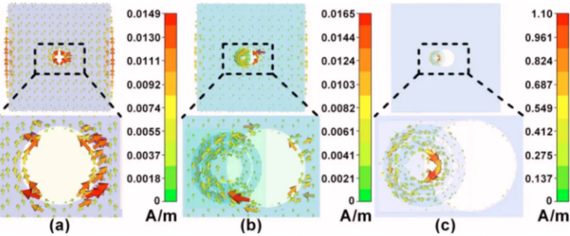
Inspection of the induced surface currents provides physical insight. Figure 5 shows the induced surface cur-rents. The magnified images are especially taken around the aperture. According to Fig. 5共a兲, the surface currents on the metal block primarily remained parallel to the metal surface and attained the highest values at the discontinuities in the absence of the SRR. The weak contribution to the radiation came from the diffractions at the edges. The presence of the CRR did not cause any dramatic changes in Fig.5共b兲. On the contrary, the surface currents turned out to be quantitatively amplified and focused around the aperture as soon as the CRR was substituted with the SRR at the enhancement fre-quency 共see the color bars in Fig. 5兲. SRR, near the slit on
the metal surface, concentrated the induced currents owing to its resonance behavior, acted like an antenna, and prepared the ground for a transmission enhancement through the opening. The metal block created image currents that nulli-fied the induced surface currents on the SRR. Then, we can identify an effective antenna area that essentially involves the uncompensated induced surface currents on the SRR within the region overlapped by the aperture. The effective antenna area determines the enhancement frequency and the enhancement factors. This is the main reason why the sample SRR resonance frequencies did not perfectly coincide with the respective enhancement frequencies. We can further ma-nipulate the effective antenna area by modifying the aperture radius. Smaller aperture radius values bring the enhancement to higher frequencies 共see Fig.4 inset兲. Misalignments
gen-erate a similar outcome. The effective area is reduced by allowing the metal plate to cover a smaller portion of the SRR that in turn lessens the enhancement factors and in-creases the enhancement frequencies 关see Fig.3共b兲兴.
In conclusion, we studied the extraordinary transmission by utilizing an electrically coupled SRR in the near field of a subwavelength aperture. The measurements and simulations demonstrated that a transmission enhancement figure of 530 could be achieved. This is a noteworthy accomplishment for an aperture with a radius of 1/20 of the wavelength of op-eration when compared with previous experiments.4 Further-more, we verified that the observed transmission enhance-ment effect is indeed due to the resonance behavior of the subwavelength resonant element by carrying out systematic experiments and numerical calculations.
This work is supported by the European Union under the projects EU-PHOME, and EU-ECONAM, and TUBITAK under Project Nos. 105A005, 106E198, and 107A004. One of the authors共E.O.兲 also acknowledges partial support from the Turkish Academy of Sciences.
1C. Genet and T. W. Ebbesen,Nature共London兲 445, 39共2007兲. 2T. Matsui, A. Agrawal, A. Nahata, and Z. V. Vardeny,Nature共London兲
446, 517共2007兲.
3H. A. Bethe,Phys. Rev. 66, 163共1944兲.
4T. W. Ebbesen, H. J. Lezec, H. F. Ghaemi, T. Thio, and P. A. Wolff,Nature
共London兲 391, 667共1998兲.
5L. Martin-Moreno, F. J. Garcia-Vidal, H. J. Lezec, K. M. Pellerin, T. Thio,
J. B. Pendry, and T. W. Ebbesen,Phys. Rev. Lett. 86, 1114共2001兲. 6W. L. Barnes, W. A. Murray, J. Dintinger, E. Devaux, and T. W. Ebbesen,
Phys. Rev. Lett. 92, 107401共2004兲.
7J. Barvo-Abad, A. Degiron, F. Przybilla, C. Genet, F. J. Garcia-Vidal, L.
Martin-Moreno, and T. W. Ebbesen,Nat. Phys. 2, 120共2006兲.
8A. Alu, F. Bilotti, N. Engetha, and L. Vegni, IEEE Trans. Antennas
Propag. 54, 1632共2006兲.
9N. Katsarakis, M. Kafesaki, I. Tsiapa, E. N. Economou, and C. M.
Souk-oulis,Photonics Nanostruct. Fundam. Appl. 5, 149共2007兲.
10R. Marques, F. Mesa, J. Martel, and F. Medina, IEEE Trans. Antennas
Propag. 51, 2572共2003兲.
11K. Aydin, A. O. Cakmak, L. Sahin, Z. Li, F. Bilotti, L. Vegni, and E.
Ozbay,Phys. Rev. Lett. 102, 013904共2009兲.
FIG. 5. 共Color online兲 共a兲 The induced surface currents on the aperture, 共b兲 aperture with CRR, and 共c兲 aperture with sample SRR A. The region around the aperture is magnified for each case for clarification.