V4b.7
DESIGN AND IMPLEMENTATION
OF A GENERAL PURPOSE
VLSI MEDIAN FILTER UNIT AND ITS APPLICATIONS
M u s t a f a K a r a m a n , Levent Onural, a n d A b d u l l a h A t a l a r Electrical and Electronics Eng. Dept., Bilkent University
POB. 8, 06572 Maltepe, Ankara, Turkey
ABSTRACT
In order to meet the changing demands of different me- dian filtering applications, a VLSI median filter unit is de- signed and implemented in 3-pm M’CMOS by employing full-custom VLSI design techniques. The unit consisk of two single-chip median filters, one extensible and one real- time. The architectures of the chips are bit-level pipelined systolic structures based on the odd/even transposition sort- ing. The extensible chip is designed for the applications requiring variable window sizes and variable word-lengths whereas the other one is for real-time applications. Various median filtering techniques are easily realized by using the designed chips together with a reasonable external hard- ware.
1. INTRODUCTION
The median filtering is a nonlinear smoothing technique that has been frequently used in many signal and image pro- cessing applications to filter out the impulsive noises while preserving the edge-information 111. In the standard median filtering applications, a window of size w , w is odd, moves on the sampled values of the signal or image, and then the median of the samples within the window is computed and written as the output element at the location of the center
of the window [2]. In terms of impulsive noise suppression, edge preservation, and ease of design, the performance of median filters are better than the other smoothing filters such as linear filters and generalized mean filters [3].
In order t o increase the performance of the median fil- ters for particular applications, various median filtering tech- niques have been developed. For impulsive noise suppres- sion, the standard median filtering technique is a good choice However, for suppression of nonimpulsive noises other tech- niques such as adaptive-length [4], separable [5] recursive [6], and weighted [7] median filtering techniques may be more convenient. For edge detection, generalized [ 8 ) , hy- brid [ 9 ] , and selective [lo] median filtering techniques are frequently used. In addition, the weighted median filtering can be also uscd for edge detection by choosing the weight coefficients properly.
Since the computation of the median of a group of ele- ments is the fundamental operation in all of the techniques cited above, their realizations can be accomplished using the standard median filter as the basic component. Thus, there have been much efforts to develop high performance software and hardware standard median filters [11,12,13,14].
However, the window size of the median filter and the word- length of the elements are not the same in different appli- cations. Also, the required speed of the filtering opera- tion varies depending on the application. A median filter which is intended as a component of a general purpose sig- nal or image processor must meet these changing demands. We propose a solution to that problem in the form of two single-clip median filters, one extensible and one real-time,
which are implemented in 3-pm M’CMOS by employing
full-custom VLSI design techniques. The extensible median filter chip is designed for the applications requiring variable word-lengths and variable window sizes whereas the real- time median filter chip is for the real-time median filtering applications. The architectures of the chips are bit-level pipelined systolic structures based on the odd/even trans- position sorting. In the following sections, the architectures, VLSI implementations, and some possible applications of the chips are presented.
2. ARCHITECTURES
2.1 Extensible Median Filter Architecture
The extensible me2ian filter is an odd/even transposi- tion sorting network which is a bit-level pipelined regular structure consisting of 9 CO npare-and-swap stages (Fig.1). Each stage consists of 5 bitwise compare-and-swap units. Each of these units serially compares two numbers at its in- puts and interchanges them if necessary so that t,he larger one is at the “top”. At the output of the last stage, the data will be sorted such that the largest will be at the top, and the median will be in the middle. At each clock. one bit from each word (total of 9 bits) enter the network and one bit of the median is obtained at the output. The Row is from the most significant bits toward the least signifi- cant bits both at the input and at the output. Because of the bitwise serial data flow, this structure allows arbitrary word-length, L.
The bitwise compare-and-swap unit (CSUI) is a finite state machine which has three legal operation states: equal ( S E = OI), paJs ( S E = 00), and swap ( S E = 10) (Fig.2). CSUl is set to the equal state at the end of each data word by a reset signal. Thus the reset signal flows through the stages of the network at a rate of one stage per clock cycle by means of the pipelined delay units. During the compl- tation, the CSUl stays in the equal state and passw til,.
input data unaltered as long as the two input bits arc. c>,ll1:ll as they flow in. However, it locks itself into the p n s s s i : l r , ~ when it first finds tha.t A , > Bi and passes the i n l n i t s I I I I : I ~ tered. On the other hand it locks itself into the. s ~ 1 1 ’ st:ltc\
when it first finds that A;
<
Bi and swaps b l a i l l p t s ,2548
CH2673-2/89/0000-2% $1.00 Q 1989 IEEEIn the extensible median filter structure given in Fig.1, the upper and lower eztension I/O’s (x+,’s and g~+’s) are used to extend the filter to larger window sizes. For w = 9, the upper and lower extension inputs are connected to logic 1’s and logic 0’s so that the corresponding compare-and- swap units act as delay units. On the other hand, the design allows the interconnections of many of these chips to form median filters for w
>
9 (Fig.3).The extensible median filter generates its outputs with a delay of w
+
L
clocks; and after the network is full, it finds one L-bit median per L clocks. Although, the result- ing speed may be sufficient for the real-time median filtering of 512 x 512 frames withL
<
5 , it is not enough for the real- time filtering of 1024 x 1024 frames withL
>
1.2.2 Real-Time Median Filter Architecture
“.d! 0:
...r: r:
...
r: 4 - 3 ....
r: 4Figure 2: Logic diagram of the compare-and-swap unit-1 (CSU1). U I I - 4 . 1 MF l”p115 I I-X) LW’C 0 1 1 1 - 4 = 0
Figure 3: Interconnections of the extensible median filters for w = 25 (MF9EE: extensible median filter with window size w = 9).
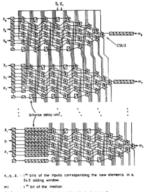
The real-time median filter is designed by interconnect- ing 8 odd/even trmsposition sorter blocks in parallel [13] (Fig.4). In this network, the data enter in such a way that the most significant bits go to the first block, the sec- ond most significant bits t o the second block, and so on. The bitwise compare-and-swap unit used in this network is slightly different than that of the extensible one, because the“swap” or “pass” information flows from upper to lower blocks so that the compare-and-swap unit takes this infor- mation, uses, updates and sends it out (Fig.5). For proper timing, the pipelined delay units are included at the input and output of the network.
The real-time median filter has nine 8-bit data inputs and it generates one 8-bit median per clock. At every clock, three new elements enter the chip, corresponding to the new elements of a sliding 3 x 3 window. Since the clock period is determined by the delay of one compare-and swap unit
(CSUZ), recent VLSI technology allows the implementation
of CSUZ at a speed larger than the real-time operation rate for the 1024 x 1024 frames with
L
= 8.S. E.
:
.
bitwme delay/
u d .x,,y, z
m i I In bit of the medlon S,.E,
b1t5 of the mputs correspcnding the new elemls hn a 3 x 3 sliding windov
Test inputs for testing of the blccks individually
Figure 4. The real-time median filter architecture
.o
8.
Figure 5: Logic diagram of the compare-and-swap unit-2
(CSU2).
3. CHIPS
Both of the extensible and real-time median filter archi- tectures are regular arrays of the bitwise compare-and-swap units. Also, their internal communication schemes are sim- ple and regular. This makes the VLSI implementations easy and straightforward 115,161. The architectures are mapped to hardware by using standard CMOS logic style [17] in 3-
pm double metal n-well process. For generation of the chip layouts, and their simulations, full-custom VLSI CAD tools
[l8,19] are used: magic for layout editing, Spice, Rnl, and Esim for simulations. The overall layouts of the chips are shown in Fig.6. The main features of the chips are given in Table.1.
( b )
Figure 6: The layouts of the median filter chips: a) exten- sible, b) real-time.
I
2.8 x 4.5I
7.2 x 6.91
[Die size (mm’)I
Transistor countI
5,0001
22.000.1
Transistors/mm’ Maximum clock frequency (MHz) Maximum throughput (mega medians/sec) Pin number Maximum power 400 40 3O/L 28 250I,
i
800Table 1: The main features of the chips, The testing of the chips are easily accomplished by the functional test techniques [20] since the operations of the cells can be selectively probed by using proper test vectors. The test vectors and the expected outputs are generated by using software tools written for these purposes. There are
500 test vectors for the extensible median filter chip, and
12,000 for the other one.
4. APPLICATIONS
The extensible and the real-time median filter chips can be selectively used in a processor environment by means of the chip enable signal that each chip has. Furthermore, one can realize any median filtering technique mentioned in the introduction by using the extensible and/or the red-time median filter chips together with or without a reasonable external hardware:
For the standard median filtering technique, the exact medians of the elements, in a window size w = 9 with arbitrary word length L , can be found by using only one extensible median filter chip. For w > 9 with arbitrary L , at most [w/9]’ ([.]I’ indicates the smallest greater integer) chips are required to find the exact medians (Fig. 3). On the other hand, the real-time
median filter chip can find the exact running medians of the elements in a window of a fixed size w = 9 with fixed word length L = 8 at the real-time rate. The extensible median filter is a favorable choice to realize the adaptive-length median filters [4], since one can change the window size from 3 to indefinitely large ones by using the extensible median filter chip(s) by applying logic 0’s or 1’s to unused inputs of the chip(s) appropriately.
For the realizations of the weighted median filters (71, the extensible median filter can be used together with a pipelined multiplier which multiplies the input data with the weight coefficients. Since all input data of
the chip are entered to the chip directly at each move of the window, one can realize an adaptive weighted median filter by changing the weight coefficients at each position of the window on the frame.
A pair of the extensible or the real-time median filter chips can be used as a selective median filter [IO] to- gether with an external control logic consisting of two full-word subtiacter and a full-word comparator.
Either the extensible or the real-time median filter chip can be used as a line-ncursiwe median filter [4] by loading the window elements from the frame ap- propriately.
The chips can be used for the realizations of the sepa- rable median filters [5] without any external hardware.
5. CONCLUDING REMARKS
A VLSI median filter unit consisting of two single-chip median filters and its applications are presented. The ar-
chitectures of the chips are modular and have regular com- munication schemes which make the VLSI implementations rather easy and straightforward. Both of the architectures are not preferable to be implemented at larger window sizes since the area is proportional to the
12.
We have chosenzu = 9, because this is the most commonly used window size in two dimensional median filtering applications.
The main contributions of this study are design and im- plementations of two single-chip versatile components for signal and image processing: an extensible median filter chip for adaptive-word-length and adaptive-window filter- ing applications, and a real-time median filter chip for real- time filtering of images with sizes up t o 1024 x 1024 pixels. Wrthermore, it is concluded that a general purpose median filter unit can be formed by selectively using the chips in a full-scale general purpose digital signal or image processor environment.
ACKNOWLEDGMENT
This research was sponsored by NATO’s Scientific Af- fairs Division in the framework of the Science for Stability Programme.
References
[l] J. W. Tukey, “Nonlinear (nonsuperposable) methods for smoothing data,” in Conf. Rec., p. 673, EASCON
1974.
[2]
N.
C. Gallagher, Jr., and G. L. Wise, “A theoreti- cal analysis of the properties of median filters,” IEEE Trans. Acoustic, Speech, and Signal Processing, vol. ASSP-29, pp. 1136-1141, Dec. 1981.[3] A. Kundu,
S.
K. Mitra, and P. P. Vaidyanathan, “Ap- plication of two-dimensional generalized mean filter- ing for removal of impulse noises from images,” IEEE Trans. Acowtic, Speech, and Signal Processing, vol. ASSP-32, NO. 3, pp. 600-609, Jun. 1984.[4] H. M. Lin and A. N. Willson, Jr., “Adaptive-length median filters for image processing,” Proc. of IEEE ISCAS‘88, pp. 2557-2560.
I .
151 T. A. Nodes and N. C. Gallagher, Jr., “Two-’
dimensional root structures and convergence properties of the separable median filter,” IEEE Trans. Acoustic, Speech, and Signal Processing, vol. ASSP-31, pp. 1350- 1365, Dec. 1983.
[6] C. G. Boncelet Jr., “Recursive algorithms and VLSI implementations for median filtering,” Proc. of IEEE ISCAS‘88, pp. 1745-1747.
[7] T. Loupas, W. N. McDidren, and P.
L.
Allan, Noise reduction in ultrasonic images by digital filtering,The British Journal of Radiology, vol. 60, pp.389-392, Apr. 1987.
Y.
H.
Lee andS.
A. Kassam, “Generalized median filtering and related nonlinear filtering techniques,” IEEE I t a m . Acowtic, Speech, and Signal Processing, vol. ASSP-33, pp. 672-683, Jun. 1985.Y.
Neuvo, P. Heinonen, and I. Defee, “Linear-median hybrid edge detectors,” IEEE h n a . Cinuita and Sys- tems, vol. CAS-34, pp. 1337-1343, NOV. 1987.s.
J. KO, Y. H. Lee, and A. T. Fam, “Selective median filters,” Proc. of IEEE ISCAS‘88, pp. 1495-1498.D. L. Knuth, The Art of Computer Programming
Searching and Sorting, vol. 3. Reading MA: Addison- Wesley, 1973.
E. Ataman, V. K. Aatre, and K. M. Wong, “A fast method for real-time median filtering,” IEEE f i n s . Acoustic, Speech, and Signal Processing, vol. ASSP-28, pp. 415-421, Aug. 1980.
K. Oflazer, “Design and implementation of a single- chip 1-D median filter,” IEEE Itans. Acoustic, Speech and Signal ProcesJing, vol. ASSP-31, pp. 1164-1168, Oct. 1983.
V. V. B. Raa and K.
S.
Rao, “A new algorithm for real- time median filtering,” IEEE Tram. Acoustic, Speech, and Signal Processing, vol. ASSP-34, pp. 1674-1675, Dec. 1986M. J. Foster and H. T. Kung, “The design of special
purpose VLSI chips,” IEEE Computer, pp. 26-40, Jan.
1980.
H. T. Kung, “Why systolic architectures?,” IEEE
Cornputer, pp. 37-46, Jan. 1982.
N.
Weste and K. Eshraghian,Principks of CMOS VLSIDesign, Reading MA: Addison-Wesley, 1985. Berkeley C A D Tools User’s Manual,
EECS
Dep., Uni- versity of California at Berkeley, 1986.VLSI Tools Reference Manual, TR#87-02-01, Release
3.1, NW Lab. Int. Sys., Dep. Computer Sci., University of Washington, Feb.1987.
[20] J. A. Abraham and W. K. hchs, “Fault and error
models for VLSI,” IEEE Proc., vol. 74, pp. 639-654, May 1986.
![Table 1: The main features of the chips, The testing of the chips are easily accomplished by the functional test techniques [20] since the operations of the cells can be selectively probed by using proper test vectors](https://thumb-eu.123doks.com/thumbv2/9libnet/5664109.113251/3.936.173.442.500.912/features-testing-accomplished-functional-techniques-operations-selectively-vectors.webp)
