a thesis
submitted to the department of computer engineering
and the institute of engineering and science
of bilkent university
in partial fulfillment of the requirements
for the degree of
master of science
By
Yi˘
githan Dedeo˘
glu
August, 2004
Assist. Prof. Dr. U˘gur G¨ud¨ukbay (Supervisor)
I certify that I have read this thesis and that in my opinion it is fully adequate, in scope and in quality, as a thesis for the degree of Master of Science.
Prof. Dr. A. Enis C¸ etin
I certify that I have read this thesis and that in my opinion it is fully adequate, in scope and in quality, as a thesis for the degree of Master of Science.
Prof. Dr. ¨Ozg¨ur Ulusoy
Approved for the Institute of Engineering and Science:
Prof. Dr. Mehmet B. Baray Director of the Institute
CLASSIFICATION FOR SMART VIDEO
SURVEILLANCE
Yi˘githan Dedeo˘glu M.S. in Computer Engineering
Supervisor: Assist. Prof. Dr. U˘gur G¨ud¨ukbay August, 2004
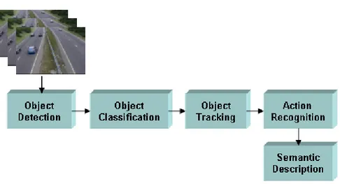
Video surveillance has long been in use to monitor security sensitive areas such as banks, department stores, highways, crowded public places and borders. The advance in computing power, availability of large-capacity storage devices and high speed network infrastructure paved the way for cheaper, multi sensor video surveillance systems. Traditionally, the video outputs are processed online by human operators and are usually saved to tapes for later use only after a forensic event. The increase in the number of cameras in ordinary surveillance systems overloaded both the human operators and the storage devices with high volumes of data and made it infeasible to ensure proper monitoring of sensitive areas for long times. In order to filter out redundant information generated by an array of cameras, and increase the response time to forensic events, assisting the human operators with identification of important events in video by the use of “smart” video surveillance systems has become a critical requirement. The making of video surveillance systems “smart” requires fast, reliable and robust algorithms for moving object detection, classification, tracking and activity analysis.
In this thesis, a smart visual surveillance system with real-time moving ob-ject detection, classification and tracking capabilities is presented. The system operates on both color and gray scale video imagery from a stationary camera. It can handle object detection in indoor and outdoor environments and under changing illumination conditions. The classification algorithm makes use of the shape of the detected objects and temporal tracking results to successfully cat-egorize objects into pre-defined classes like human, human group and vehicle. The system is also able to detect the natural phenomenon fire in various scenes reliably. The proposed tracking algorithm successfully tracks video objects even in full occlusion cases. In addition to these, some important needs of a robust
smart video surveillance system such as removing shadows, detecting sudden il-lumination changes and distinguishing left/removed objects are met.
Keywords: Video-Based Smart Surveillance, Moving Object Detection, Back-ground Subtraction, Object Tracking, Silhouette-Based Object Classification, Fire Detection.
BULMA, TAK˙IP ETME VE SINIFLANDIRMA
Yi˘githan Dedeo˘glu
Bilgisayar M¨uhendisli˘gi, Y¨uksek Lisans Tez Y¨oneticisi: Yrd. Do¸c. Dr. U˘gur G¨ud¨ukbay
A˘gustos, 2004
Video g¨ozetimi hassas g¨uvenlik gerektiren banka, alı¸sveri¸s merkezi, otoyol gibi kamuya a¸cık kalabalık alanları izlemek i¸cin uzun s¨uredir kullanılmaktadır. Bilgi i¸slem g¨uc¨undeki artı¸s, y¨uksek kapasiteli kayıt cihazlarının ¨uretilmesi ve hızlı a˘g altyapısı ucuz ve ¸cok algılayıcılı sistemlerin ¨uretilmesine ¨on ayak olmu¸stur. Elde edilen video g¨or¨unt¨us¨u canlı olarak operat¨orlerce izlenir ve daha sonra adli bir olayda kullanılmak ¨uzere kaydedilir. Sıradan bir g¨ozetim sisteminde bulunan kamera sayısındaki teknolojinin geli¸smesine ba˘glı artı¸s, hem operat¨orleri hem de kayıt cihazlarını a¸sırı hacimdeki bilgiye maruz bırakmı¸s ve hasas g¨uvenlik b¨olgelerinin uzun s¨ureli video ile g¨ozetimini verimsiz kılmı¸stır. Bir dizi kamera tarafından ¨uretilen ve ¸co˘gunlukla gereksiz olan g¨or¨unt¨u bilgisini elemek ve adli olaylara m¨udahale zamanını kısaltmak i¸cin operat¨orlere videodaki ¨onemli olayları belirleyerek yardımcı olacak “akıllı” video g¨ozetim sistemlerini geli¸stirmek kri-tik bir ihtiya¸c haline gelmi¸stir. Video g¨ozetim sistemlerini “akıllı” hale getirmek hızlı, g¨uvenilir ve hatasız nesne bulma, sınıflandırma ve takip etme algoritmalarını gerektirmektedir.
Bu tezde, nesne bulma, sınıflandırma ve takip etme yeteneklerine sahip bir “akıllı” video g¨ozetim sistemi sunulmu¸stur. Sistem sabit bir kameradan elde edilen renkli ve renksiz g¨or¨unt¨uler ¨uzerinde ¸calı¸sabilmektedir. ˙I¸c ve dı¸s mekanlarda, de˘gi¸sen ı¸sık ko¸sulları altında ¸cekilen video g¨or¨unt¨ulerinde yer alan nesneler bulunabilmektedir. Nesne sınıflandırma algoritması bulunan nes-neleri ¸sekillerinden ve nesne takip etme algoritmasından yararlanarak ¨onceden tanımlanmı¸s olan insan, insan grubu ve ara¸c gibi sınıflara ayırabilmektedir.
¨
Onerilen sistem bina ve a¸cık alan g¨uvenli˘ginde ¸cok ¨onem arzeden yangını da g¨uvenilir bir ¸sekilde bulabilmektedir. Nesne takip algoritması ba¸ska nesneler tarafından perdelenen nesneleri de takip edebilmektedir. T¨um bu ¨ozelliklere ek
olarak video g¨ozetim sistemlerinin ¨onemli ihtiyacı olan g¨olge b¨olgelerinin silin-mesi, ani ı¸sık de˘gi¸simlerinin algılanması ve bırakılan ya da alınan nesnelerinin bulunması da ger¸cekle¸stirebilmektedir.
Anahtar s¨ozc¨ukler : Akıllı Video G¨ozetimi, Hareketli Nesne Bulma, Arka Plan Kestirimi, Nesne Takip Etme, Siluete Dayalı Nesne Sınıflandırma, Ate¸s Bulma.
I would like to express my gratitude to Assist. Prof. Dr. U˘gur G¨ud¨ukbay for his supervision, encouragement, suggestions and trust throughout the development of this theses.
I owe special thanks to Prof. Dr. A. Enis C¸ etin for his guidance, support and invaluable discussions that encouraged me in my research. I am grateful to my thesis committee member Prof. Dr. ¨Ozg¨ur Ulusoy for reading my thesis and helpful comments.
I am also thankful to Dr. M. Bilgay Akhan (CEO, visiOprime, UK) for supporting some parts of our research financially.
Without the support of my colleagues this research would not be that much enjoyable for me. I am especially grateful to Beh¸cet U˘gur T¨oreyin for his invaluable contributions, cooperation and discussions. I am also indebted to Alptekin Temizel (visiOprime, UK), Anıl Aksay and Erdem Dengel for their support and comments.
I also would like to thank Aslı for her love and morale support that made everything easier for me.
Finally, my biggest gratitude is to my family (Demirhan, Hacer, Tu˘gcihan Dedeo˘glu and Hilmi, ¨Oznur C¸ elik) for their endless love, support and trust in me. Without them I would never come up to this stage.
1 Introduction 1
1.1 Overview . . . 5
1.2 Motivation . . . 7
1.3 Organization of the Thesis . . . 7
2 A Survey in Smart Video Surveillance 8 2.1 Moving Object Detection . . . 8
2.1.1 Background Subtraction . . . 9
2.1.2 Statistical Methods . . . 10
2.1.3 Temporal Differencing . . . 11
2.1.4 Optical Flow . . . 12
2.1.5 Shadow and Light Change Detection . . . 13
2.2 Object Classification . . . 14
2.2.1 Shape-based Classification . . . 14
2.2.2 Motion-based Classification . . . 15
2.3 Fire Detection . . . 16
2.4 Object Tracking . . . 16
3 Object Detection and Tracking 19 3.1 Object Detection . . . 22
3.1.1 Foreground Detection . . . 24
3.1.2 Pixel Level Post-Processing . . . 30
3.1.3 Detecting Connected Regions . . . 38
3.1.4 Region Level Post-Processing . . . 39
3.1.5 Extracting Object Features . . . 39
3.2 Object Tracking . . . 41
3.2.1 Correspondence-based Object Matching . . . 41
3.2.2 Occlusion Handling . . . 47
3.2.3 Detecting Left and Removed Objects . . . 49
4 Object Classification 53 4.1 Silhouette Template Based Classification . . . 54
4.1.1 Object Silhouette Extraction . . . 54
4.2 Silhouette Template Database . . . 54
4.3 The Classification Metric . . . 57
5 Fire Detection 63
5.1 Color Detection . . . 65
5.2 Temporal Variance Analysis . . . 67
5.3 Temporal Periodicity Analysis . . . 68
5.4 Spatial Variance Analysis . . . 69
5.5 Fire Region Growing . . . 70
5.6 Temporal Persistency and Growth Checks . . . 70
6 Experimental Results 72 6.1 Test Application and System . . . 72
6.2 Object Detection and Tracking . . . 73
6.3 Object Classification . . . 73
6.4 Fire Detection . . . 75
7 Conclusion and Future Work 78
2.1 A generic framework for smart video processing algorithms. . . 9
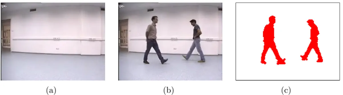
2.2 Temporal differencing sample. (a) A sample scene with two moving objects. (b) Temporal differencing fails to detect all moving pixels of the object on the left hand side since it is uniform colored. The detected moving regions are marked with red pixels. . . 12
3.1 The system block diagram. . . 20
3.2 The object detection system diagram. . . 23
3.3 Adaptive Background Subtraction sample. (a) Estimated back-ground (b) Current image (c) Detected region . . . 27
3.4 Two different views of a sample pixel processes (in blue) and corre-sponding Gaussian Distributions shown as alpha blended red spheres. 29
3.5 Pixel level noise removal sample. (a) Estimated background image (b) Current image (c) Detected foreground regions before noise removal (d) Foreground regions after noise removal . . . 32
3.6 RGB vectors of current image pixel ˆIx and corresponding
back-ground pixel ˆBx. . . 34
3.7 Shadow removal sample. (a) Estimated background (b) Current image (c) Detected foreground pixels (shown as red) and shadow pixels (shown as green) (d) Foreground pixels after shadow pixels
are removed . . . 35
3.8 Sudden light change sample. (a) The scene before sudden light change (b) The same scene after sudden light change . . . 36
3.9 Detecting true light change. (a) Estimated reference background (b) Background’s gradient (c) Current image (d) Current image’s gradient (e) The gradient difference . . . 37
3.10 Connected component labeling sample. (a) Estimated background (b) Current image (c) Filtered foreground pixels and connected and labeled regions with bounding boxes . . . 38
3.11 The object tracking system diagram. . . 42
3.12 The correspondence-based object matching method. . . 43
3.13 Sample object matching graph. . . 44
3.14 Occlusion detection sample case. . . 47
3.15 Object identification after occlusion. (a) Image before occlusion (b) Image after occlusion (c) Color histogram of object A before occlusion (d) Color histogram of object B before occlusion (e) Color histogram of object A after occlusion (f) Color histogram of object B after occlusion (g) Normalized color histogram distance table of objects A and B . . . 50
3.16 Distinguishing left and removed objects. (a) Scene background (b) Regions R and S (c) Left object sample (d) Removed object sample 52 4.1 Sample detected foreground object regions and extracted silhouettes. 55 4.2 Sample silhouette template database with labels. . . 56
4.3 Sample object silhouette and its corresponding original and scaled distance signals. (a) Object silhouette (b) Distance signal (c) Scaled distance signal . . . 58
4.4 Object classification sample. (a) Sample query object (b) Tem-plate database objects with distance signals. The type of each object (H: Human, HG: Human Group, V: Vehicle) and the dis-tance (D) between the query object and each database object are shown below the objects. . . 61
4.5 Object type histogram for a sample detected object. ((a), (c), (e)) Detected object ((b), (d), (f)) Corresponding object type histogram 62
5.1 The fire detection system diagram. . . 64
5.2 Sample fire color cloud in RGB space and Gaussian distribution spheres which cover the cloud shown from two different views. . . 66
5.3 Temporal variance of the intensity of fire colored pixels. (a) A pixel in true fire region (b) A pixel of a fire colored object . . . . 67
5.4 Spatial variance of the intensity of pixels. (a) A true fire region V ariance = 1598 (b) A fire colored object region V ariance = 397 69
6.1 Sample video frames before and after occlusions. . . 74
6.1 Performance of object detection algorithms . . . 73
6.2 Occlusion handling results for sample clips . . . 74
6.3 Number of object types in the sample object template database . 75
6.4 Confusion matrix for object classification . . . 75
6.5 Fire detection performance comparison . . . 77
Introduction
Video surveillance systems have long been in use to monitor security sensitive areas. The history of video surveillance consists of three generations of systems which are called 1GSS, 2GSS and 3GSS [36].
The first generation surveillance systems (1GSS, 1960-1980) were based on analog sub systems for image acquisition, transmission and processing. They ex-tended human eye in spatial sense by transmitting the outputs of several cameras monitoring a set of sites to the displays in a central control room. They had the major drawbacks like requiring high bandwidth, difficult archiving and retrieval of events due to large number of video tape requirements and difficult online event detection which only depended on human operators with limited attention span.
The next generation surveillance systems (2GSS, 1980-2000) were hybrids in the sense that they used both analog and digital sub systems to resolve some drawbacks of its predecessors. They made use of the early advances in digital video processing methods that provide assistance to the human operators by filtering out spurious events. Most of the work during 2GSS is focused on real-time event detection.
Third generation surveillance systems (3GSS, 2000- ) provide end-to-end digi-tal systems. Image acquisition and processing at the sensor level, communication
through mobile and fixed heterogeneous broadband networks and image storage at the central servers benefit from low cost digital infrastructure.
Unlike previous generations, in 3GSS some part of the image processing is distributed towards the sensor level by the use of intelligent cameras that are able to digitize and compress acquired analog image signals and perform image analysis algorithms like motion and face detection with the help of their attached digital computing components.
The ultimate goal of 3GSS is to allow video data to be used for online alarm generation to assist human operators and for offline inspection effectively. In order to achieve this goal, 3GSS will provide smart systems that are able to generate real-time alarms defined on complex events and handle distributed storage and content-based retrieval of video data.
The making of video surveillance systems “smart” requires fast, reliable and robust algorithms for moving object detection, classification, tracking and activity analysis. Starting from the 2GSS, a considerable amount of research has been devoted for the development of these intelligent algorithms.
Moving object detection is the basic step for further analysis of video. It han-dles segmentation of moving objects from stationary background objects. This not only creates a focus of attention for higher level processing but also decreases computation time considerably. Commonly used techniques for object detection are background subtraction, statistical models, temporal differencing and optical flow. Due to dynamic environmental conditions such as illumination changes, shadows and waving tree branches in the wind object segmentation is a diffi-cult and significant problem that needs to be handled well for a robust visual surveillance system.
Object classification step categorizes detected objects into predefined classes such as human, vehicle, animal, clutter, etc. It is necessary to distinguish objects from each other in order to track and analyze their actions reliably. Currently, there are two major approaches towards moving object classification, which are shape-based and motion-based methods [49]. Shape-based methods make use of
the objects’ 2D spatial information whereas motion-based methods use temporal tracked features of objects for the classification solution. Detecting natural phe-nomenon such as fire and smoke may be incorporated into object classification components of the visual surveillance systems. Detecting fire and raising alarms make the human operators take precautions in a shorter time which would save properties, forests and animals from catastrophic consequences.
The next step in the video analysis is tracking, which can be simply defined as the creation of temporal correspondence among detected objects from frame to frame. This procedure provides temporal identification of the segmented regions and generates cohesive information about the objects in the monitored area such as trajectory, speed and direction. The output produced by tracking step is generally used to support and enhance motion segmentation, object classification and higher level activity analysis.
The final step of the smart video surveillance systems is to recognize the be-haviors of objects and create high-level semantic descriptions of their actions. It may simply be considered as a classification problem of the temporal activity sig-nals of the objects according to pre-labeled reference sigsig-nals representing typical human actions [49].
The outputs of these algorithms can be used both for providing the human operator with high level data to help him to make the decisions more accurately and in a shorter time and for offline indexing and searching stored video data effectively. The advances in the development of these algorithms would lead to breakthroughs in applications that use visual surveillance. Below are some scenarios that smart surveillance systems and algorithms might handle [10, 2, 16, 33, 15, 13, 45, 27, 41, 39, 49, 21]:
Public and commercial security:
• Monitoring of banks, department stores, airports, museums, stations, pri-vate properties and parking lots for crime prevention and detection
• Surveillance of properties and forests for fire detection
• Observation of the activities of elderly and infirm people for early alarms and measuring effectiveness of medical treatments
• Access control
Smart video data mining:
• Measuring traffic flow, pedestrian congestion and athletic performance
• Compiling consumer demographics in shopping centers and amusement parks
• Extracting statistics from sport activities
• Counting endangered species
• Logging routine maintenance tasks at nuclear and industrial facilities
• Artistic performance evaluation and self learning
Law enforcement:
• Measuring speed of vehicles
• Detecting red light crossings and unnecessary lane occupation
Military security:
• Patrolling national borders
• Measuring flow of refugees
• Monitoring peace treaties
• Assisting battlefield command and control
The use of smart object detection, tracking and classification algorithms are not limited to video surveillance only. Other application domains also benefit from the advances in the research on these algorithms. Some examples are virtual reality, video compression, human machine interface, augmented reality, video editing and multimedia databases.
1.1
Overview
In this thesis, we present a smart visual surveillance system with real-time moving object detection, classification and tracking capabilities. The system operates on both color and gray scale video imagery from a stationary camera.
In the proposed system moving object detection is handled by the use of an adaptive background subtraction scheme [10] which reliably works in indoor and outdoor environments. We also present two other object detection schemes, temporal differencing [10] and adaptive background mixture models [44], for per-formance and detection quality comparison.
In adaptive background subtraction method, a reference background is ini-tialized at the start of the system with the first few frames of video and updated to adapt to short and long term dynamic scene changes during the operational period. At each new frame, foreground pixels are detected by subtracting the intensity values from the background and filtering the absolute value of the dif-ferences with a dynamic threshold per pixel. The reference background and the threshold values are updated by using the foreground pixel information. The detected foreground pixels usually contain noise due to image acquisition errors, small movements like tree leaves, reflections and foreground objects with textures colored similar to the background. These isolated pixels are filtered by the use of a sequence of morphological operations dilation and erosion. After this step, the individual pixels are grouped and labeled by using a two pass component labeling algorithm to create connected moving regions. These regions are further
processed to group disconnected blobs and to eliminate relatively small sized re-gions. After grouping, each detected foreground object is represented with its bounding box, area, center of mass and color histogram which will be used in later steps.
After segmenting moving pixels from the static background of the scene, con-nected regions are classified into predetermined object categories human, human group and vehicle. The classification algorithm depends on the comparison of the silhouettes of the detected objects with pre-labeled (classified) templates in an object silhouette database. The template database is created by collecting sample object silhouettes from sample videos and labeling them manually with appropriate categories. The silhouettes of the objects are extracted from the con-nected foreground regions by using a contour tracing algorithm [19]. Next, the distance between each boundary pixel and the center of mass point is calculated to create a distance signal starting from the top pixel and continuing clock-wise until reaching the same pixel. The distance signals are first normalized to be of the same length, then smoothed and finally normalized again to cover the same area. The comparison metric used in matching the templates with the detected objects are the L1 distance [42] of normalized silhouette distance signals. The
class of the template silhouette with minimum distance from the detected object’s silhouette is assigned to the object’s class. Temporal tracking information is used to support classification decision.
Detecting the natural phenomenon fire besides normal object motion would be an advantage of a visual surveillance system, thus, the presented system is able to detect fire in indoor and outdoor environments. Conventional point smoke and fire detectors typically detect the presence of certain particles generated by smoke and fire by ionization or photometry. An important weakness of point detectors is that they are distance limited and fail in open or large spaces. The strength of using video in fire detection is the ability to serve large and open spaces. Current fire and flame detection algorithms are based on the use of color and simple motion information in video [27]. In addition to detecting fire and flame colored moving regions, the method presented in this thesis analyzes the motion patterns, the temporal periodicity and spatial variance of high-frequency
behavior extensively.
As the final step in the presented system, the tracking algorithm tracks the detected objects in successive frames by using a correspondence-based match-ing scheme. It also handles multi-occlusion cases where some objects might be fully occluded by others. It uses 2D object features such as position and size to match corresponding objects from frame to frame. It keeps color histograms of detected objects in order resolve object identities after a split of an occlusion group. The output of the tracking step supports both motion segmentation and object classification steps.
1.2
Motivation
Understanding activities of objects moving in a scene by the use of video is both a challenging scientific problem and a very fertile domain with many promising applications. Thus, it draws attentions of several researchers, institutions and commercial companies [49]. Our motivation in studying this problem is to create a visual surveillance system with real-time moving object detection, classification, tracking and activity analysis capabilities. The presented system handles all of the above methods except activity recognition which will likely be the future step of our research.
1.3
Organization of the Thesis
The remaining part of this thesis is organized as follows. Chapter 2 presents a brief survey in moving object detection, tracking and classification for video surveillance applications. Our methods for moving object detection and tracking are explained in Chapter 3. Our novel object classification method is presented in Chapter 4. In the next chapter we explain the fire detection approach. Ex-perimental results of the proposed system are presented in Chapter 6. Finally, Chapter 7 concludes the thesis with the suggestions for future research.
A Survey in Smart Video
Surveillance
There have been a number of surveys about object detection, classification, track-ing and activity analysis in the literature [13, 1, 49]. The survey we present here covers only those work that are in the same context as our study. However, for comprehensive completeness, we also give brief information on some techniques which are used for similar tasks that are not covered in our study.
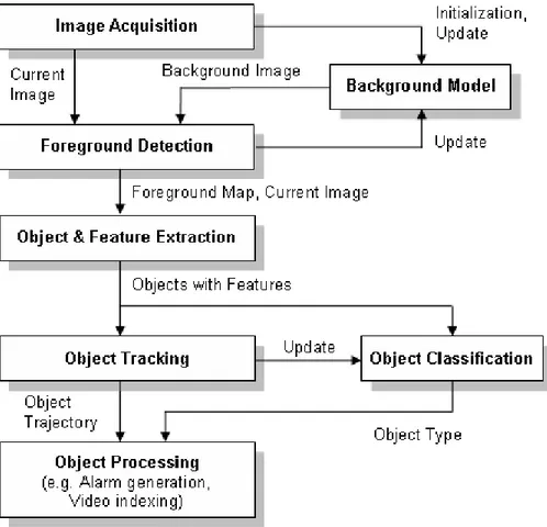
A generic video processing framework for smart algorithms is shown in Fig-ure 2.1. Although, some steps require interchange of information with other levels, this framework provides a good structure for the discussion throughout this survey.
2.1
Moving Object Detection
Each application that benefit from smart video processing has different needs, thus requires different treatment. However, they have something in common: moving objects. Thus, detecting regions that correspond to moving objects such as people and vehicles in video is the first basic step of almost every vision system
Figure 2.1: A generic framework for smart video processing algorithms.
since it provides a focus of attention and simplifies the processing on subsequent analysis steps. Due to dynamic changes in natural scenes such as sudden illu-mination and weather changes, repetitive motions that cause clutter (tree leaves moving in blowing wind), motion detection is a difficult problem to process re-liably. Frequently used techniques for moving object detection are background subtraction, statistical methods, temporal differencing and optical flow whose descriptions are given below.
2.1.1
Background Subtraction
Background subtraction is particularly a commonly used technique for motion segmentation in static scenes [34]. It attempts to detect moving regions by subtracting the current image pixel-by-pixel from a reference background image that is created by averaging images over time in an initialization period. The pixels where the difference is above a threshold are classified as foreground. After creating a foreground pixel map, some morphological post processing operations such as erosion, dilation and closing are performed to reduce the effects of noise and enhance the detected regions. The reference background is updated with new images over time to adapt to dynamic scene changes.
There are different approaches to this basic scheme of background subtrac-tion in terms of foreground region detecsubtrac-tion, background maintenance and post processing.
In [20] Heikkila and Silven uses the simple version of this scheme where a pixel at location (x, y) in the current image It is marked as foreground if
|It(x, y) − Bt(x, y)| > τ (2.1)
is satisfied where τ is a predefined threshold. The background image BT is
up-dated by the use of an Infinite Impulse Response (IIR) filter as follows:
Bt+1 = αIt+ (1 − α)Bt (2.2)
The foreground pixel map creation is followed by morphological closing and the elimination of small-sized regions.
Although background subtraction techniques perform well at extracting most of the relevant pixels of moving regions even they stop, they are usually sensitive to dynamic changes when, for instance, stationary objects uncover the back-ground (e.g. a parked car moves out of the parking lot) or sudden illumination changes occur.
2.1.2
Statistical Methods
More advanced methods that make use of the statistical characteristics of individ-ual pixels have been developed to overcome the shortcomings of basic background subtraction methods. These statistical methods are mainly inspired by the back-ground subtraction methods in terms of keeping and dynamically updating statis-tics of the pixels that belong to the background image process. Foreground pixels are identified by comparing each pixel’s statistics with that of the background model. This approach is becoming more popular due to its reliability in scenes that contain noise, illumination changes and shadow [49].
represented with its minimum (M ) and maximum (N ) intensity values and max-imum intensity difference (D) between any consecutive frames observed during initial training period where the scene contains no moving objects. A pixel in the current image It is classified as foreground if it satisfies:
|M (x, y) − It(x, y)| > D(x, y) or |N (x, y) − It(x, y)| > D(x, y) (2.3)
After thresholding, a single iteration of morphological erosion is applied to the detected foreground pixels to remove one-pixel thick noise. In order to grow the eroded regions to their original sizes, a sequence of erosion and dilation is performed on the foreground pixel map. Also, small-sized regions are eliminated after applying connected component labeling to find the regions. The statistics of the background pixels that belong to the non-moving regions of current image are updated with new image data.
As another example of statistical methods, Stauffer and Grimson [44] de-scribed an adaptive background mixture model for real-time tracking. In their work, every pixel is separately modeled by a mixture of Gaussians which are up-dated online by incoming image data. In order to detect whether a pixel belongs to a foreground or background process, the Gaussian distributions of the mixture model for that pixel are evaluated. An implementation of this model is used in our system and its details are explained in Section 3.1.1.2.
2.1.3
Temporal Differencing
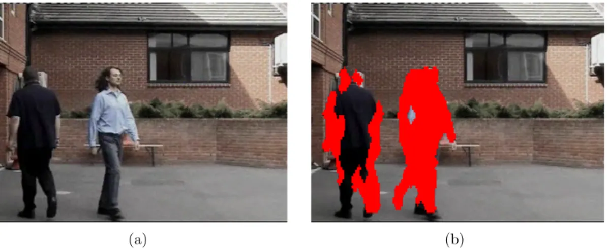
Temporal differencing attempts to detect moving regions by making use of the pixel-by-pixel difference of consecutive frames (two or three) in a video sequence. This method is highly adaptive to dynamic scene changes, however, it generally fails in detecting whole relevant pixels of some types of moving objects. A sample object for inaccurate motion detection is shown in Figure 2.2. The mono colored region of the human on the left hand side makes the temporal differencing al-gorithm to fail in extracting all pixels of the human’s moving region. Also, this method fails to detect stopped objects in the scene. Additional methods need to be adopted in order to detect stopped objects for the success of higher level
(a) (b)
Figure 2.2: Temporal differencing sample. (a) A sample scene with two moving objects. (b) Temporal differencing fails to detect all moving pixels of the object on the left hand side since it is uniform colored. The detected moving regions are marked with red pixels.
processing.
Lipton et al. presented a two-frame differencing scheme where the pixels that satisfy the following equation are marked as foreground [29].
|It(x, y) − It−1(x, y)| > τ (2.4)
In order to overcome shortcomings of two frame differencing in some cases, three frame differencing can be used [49]. For instance, Collins et al. developed a hybrid method that combines three-frame differencing with an adaptive back-ground subtraction model for their VSAM project [10]. The hybrid algorithm successfully segments moving regions in video without the defects of temporal differencing and background subtraction.
2.1.4
Optical Flow
Optical flow methods make use of the flow vectors of moving objects over time to detect moving regions in an image. They can detect motion in video se-quences even from a moving camera, however, most of the optical flow methods
are computationally complex and cannot be used real-time without specialized hardware [49].
2.1.5
Shadow and Light Change Detection
The algorithms described above for motion detection perform well on indoor and outdoor environments and have been used for real-time surveillance for years. However, without special care, most of these algorithms are susceptible to both local (e.g. shadows and highlights) and global illumination changes (e.g. sun be-ing covered/uncovered by clouds). Shadows cause the motion detection methods fail in segmenting only the moving objects and make the upper levels such as object classification to perform inaccurate. The proposed methods in the litera-ture mostly use either chromaticity [21, 35, 6, 53, 26] or stereo [15] information to cope with shadows and sudden light changes.
Horprasert et al. present a novel background subtraction and shadow detec-tion method [21]. In their method, each pixel is represented by a color model that separates brightness from the chromaticity component. A given pixel is classified into four different categories (background, shaded background or shadow, high-lighted background and moving foreground object) by calculating the distortion of brightness and chromaticity between the background and the current image pixels. Like [21], the approach described by McKenna et al. in [35] uses chro-maticity and gradient information to cope with shadows. They make use of the observation that an area cast into shadow results in significant change in intensity without much change in chromaticity. They also use the gradient information in moving regions to ensure reliability of their method in ambiguous cases.
The method presented in [6] adopts a shadow detection scheme which depends on two heuristics: a) pixel intensity values within shadow regions tend to decrease in most cases when compared to the background image, b) the intensity reduction rate changes smoothly between neighboring pixels and most shadow edges do not have strong edges.
An efficient method to deal with shadows is using stereo as presented in W4S [15] system. In W4S, stereo image is generated by an inexpensive real-time device called SVM which uses two or more images to calculate a range image by using simple stereo image geometry. With the help of the range information pro-vided by SVM, W4S is able to cope with shadows, sudden illumination changes and complex occlusion cases.
In some systems, a global light change is detected by counting the number of foreground pixels and if the total number exceeds some threshold (e.g. 50% of the total image size), the system is reset to adapt to the sudden illumination change [37, 55].
2.2
Object Classification
Moving regions detected in video may correspond to different objects in real-world such as pedestrians, vehicles, clutter, etc. It is very important to recognize the type of a detected object in order to track it reliably and analyze its activities correctly. Currently, there are two major approaches towards moving object classification which are shape-based and motion-based methods [49]. Shape-based methods make use of the objects’ 2D spatial information whereas motion-based methods use temporally tracked features of objects for the classification solution.
2.2.1
Shape-based Classification
Common features used in shape-based classification schemes are the bounding rectangle, area, silhouette and gradient of detected object regions.
The approach presented in [29] makes use of the objects’ silhouette contour length and area information to classify detected objects into three groups: human, vehicle and other. The method depends on the assumption that humans are, in general, smaller than vehicles and have complex shapes. Dispersedness is used as the classification metric and it is defined in terms of object’s area and contour
length (perimeter) as follows:
Dispersedness = P erimeter
2
Area (2.5)
Classification is performed at each frame and tracking results are used to improve temporal classification consistency.
The classification method developed by Collins et al. [10] uses view dependent visual features of detected objects to train a neural network classifier to recognize four classes: human, human group, vehicle and clutter. The inputs to the neural network are the dispersedness, area and aspect ratio of the object region and the camera zoom magnification. Like the previous method, classification is performed at each frame and results are kept in a histogram to improve temporal consistency of classification.
Saptharishi et al. propose a classification scheme which uses a logistic linear neural network trained with Differential Learning to recognize two classes: vehi-cle and people [41]. Papageorgiou et al. presents a method that makes use of the Support Vector Machine classification trained by wavelet transformed object features (edges) in video images from a sample pedestrian database [38]. This method is used to recognize moving regions that correspond to humans.
Another classification method proposed by Brodsky et al. [11] uses a Radial Basis Function (RBF) classifier which has a similar architecture like a three-layer back-propagation network. The input to the classifier is the normalized gradient image of the detected object regions.
2.2.2
Motion-based Classification
Some of the methods in the literature use only temporal motion features of ob-jects in order to recognize their classes [8, 51, 28]. In general, they are used to distinguish non-rigid objects (e.g. human) from rigid objects (e.g. vehicles). The method proposed in [8] is based on the temporal self-similarity of a moving object. As an object that exhibits periodic motion evolves, its self-similarity mea-sure also shows a periodic motion. The method exploits this clue to categorize
moving objects using periodicity.
Optical flow analysis is also useful to distinguish rigid and non-rigid objects. A. J. Lipton proposed a method that makes use of the local optical flow analysis of the detected object regions [28]. It is expected that non-rigid objects such as humans will present high average residual flow whereas rigid objects such as vehicles will present little residual flow. Also, the residual flow generated by human motion will have a periodicity. By using this cue, human motion, thus humans, can be distinguished from other objects such as vehicles.
2.3
Fire Detection
The number of papers that discuss fire detection using video is very few in com-puter vision literature. Most of the proposed methods exploit the color and motion features of fire.
Healey et al. [18] use a model which is based only on color characteristics of fire. Obviously this method generates false alarms due to fire colored regions. An improved approach which makes use of motion information as well as the color property is presented by Philips et al. [23].
Recently, Liu and Ahuja [30] presented a method that defines spectral, spatial and temporal models of fire to detect its presence in video. The spectral model is represented in terms of fire pixel color probability density. The spatial model describes the spatial structure of a fire region and the temporal model captures the changes in the spatial structure over time.
2.4
Object Tracking
Tracking is a significant and difficult problem that arouses interest among com-puter vision researchers. The objective of tracking is to establish correspondence of objects and object parts between consecutive frames of video. It is a significant
task in most of the surveillance applications since it provides cohesive temporal data about moving objects which are used both to enhance lower level processing such as motion segmentation and to enable higher level data extraction such as activity analysis and behavior recognition. Tracking has been a difficult task to apply in congested situations due to inaccurate segmentation of objects. Common problems of erroneous segmentation are long shadows, partial and full occlusion of objects with each other and with stationary items in the scene. Thus, deal-ing with shadows at motion detection level and copdeal-ing with occlusions both at segmentation level and at tracking level is important for robust tracking.
Tracking in video can be categorized according to the needs of the applications it is used in or according to the methods used for its solution. Whole body tracking is generally adequate for outdoor video surveillance whereas objects’ part tracking is necessary for some indoor surveillance and higher level behavior understanding applications.
There are two common approaches in tracking objects as a whole [2]: one is based on correspondence matching and other one carries out explicit tracking by making use of position prediction or motion estimation. On the other hand, the methods that track parts of objects (generally humans) employ model-based schemes to locate and track body parts. Some example models are stick figure, Cardboard Model [25], 2D contour and 3D volumetric models.
W4 [17] combines motion estimation methods with correspondence matching to track objects. It is also able to track parts of people such as heads, hands, torso and feet by using the Cardboard Model [25] which represents relative positions and sizes of body parts. It keeps appearance templates of individual objects to handle matching even in merge and split cases.
Amer [2] presents a non-linear voting based scheme for tracking objects as a whole. It integrates object features like size, shape, center of mass and motion by voting and decides final matching with object correspondence. This method can also detect object split and fusion and handle occlusions.
algorithm. The algorithm incorporates size and positions of objects for seeding and maintaining a set of Kalman filters for motion estimation. Also, Extended Kalman filters are used for trajectory prediction and occlusion handling in the work of Rosales and Sclaroff [40].
As an example of model based body part tracking system, Pfinder [52] makes use of a multi-class statistical model of color and shape to track head and hands of people in real-time.
Object Detection and Tracking
The overview of our real time video object detection, classification and tracking system is shown in Figure 3.1. The proposed system is able to distinguish transi-tory and stopped foreground objects from static background objects in dynamic scenes; detect and distinguish left and removed objects; classify detected objects into different groups such as human, human group and vehicle; track objects and generate trajectory information even in multi-occlusion cases and detect fire in video imagery. In this and following chapters we describe the computational models employed in our approach to reach the goals specified above.
Our system is assumed to work real time as a part of a video-based surveillance system. The computational complexity and even the constant factors of the algorithms we use are important for real time performance. Hence, our decisions on selecting the computer vision algorithms for various problems are affected by their computational run time performance as well as quality. Furthermore, our system’s use is limited only to stationary cameras and video inputs from Pan/Tilt/Zoom cameras where the view frustum may change arbitrarily are not supported.
The system is initialized by feeding video imagery from a static camera moni-toring a site. Most of the methods are able to work on both color and monochrome video imagery. The first step of our approach is distinguishing foreground objects
from stationary background. To achieve this, we use a combination of adaptive background subtraction and low-level image post-processing methods to create a foreground pixel map at every frame. We then group the connected regions in the foreground map to extract individual object features such as bounding box, area, center of mass and color histogram.
Our novel object classification algorithm makes use of the foreground pixel map belonging to each individual connected region to create a silhouette for the object. The silhouette and center of mass of an object are used to generate a distance signal. This signal is scaled, normalized and compared with pre-labeled signals in a template database to decide on the type of the object. The output of the tracking step is used to attain temporal consistency in the classification step.
The object tracking algorithm utilizes extracted object features together with a correspondence matching scheme to track objects from frame to frame. The color histogram of an object produced in previous step is used to match the correspondences of objects after an occlusion event. The output of the tracking step is object trajectory information which is used to calculate direction and speed of the objects in the scene.
After gathering information on objects’ features such as type, trajectory, size and speed various high level processing can be applied on these data. A possible use is real-time alarm generation by pre-defining event predicates such as “A human moving in direction d at speed more than s causes alarm a1.” or “A
vehicle staying at location l more than t seconds causes alarm a2.”. Another
opportunity we may make use of the produced video object data is to create an index on stored video data for offline smart search. Both alarm generation and video indexing are critical requirements of a visual surveillance system to increase response time to forensic events.
The remainder of this chapter presents the computational models and methods we adopted for object detection and tracking. Our object classification approach is explained in the next chapter.
3.1
Object Detection
Distinguishing foreground objects from the stationary background is both a signif-icant and difficult research problem. Almost all of the visual surveillance systems’ first step is detecting foreground objects. This both creates a focus of attention for higher processing levels such as tracking, classification and behavior under-standing and reduces computation time considerably since only pixels belonging to foreground objects need to be dealt with. Short and long term dynamic scene changes such as repetitive motions (e. g. waiving tree leaves), light reflectance, shadows, camera noise and sudden illumination variations make reliable and fast object detection difficult. Hence, it is important to pay necessary attention to object detection step to have reliable, robust and fast visual surveillance system.
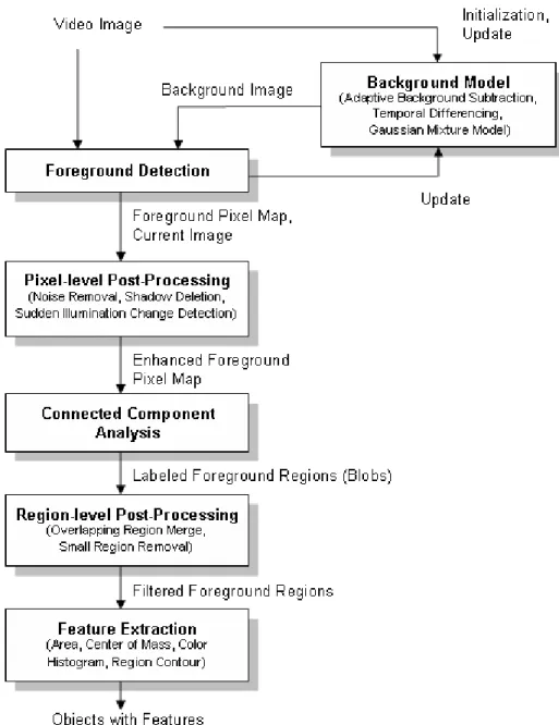
The system diagram of our object detection method is shown in Figure 3.2. Our method depends on a six stage process to extract objects with their features in video imagery. The first step is the background scene initialization. There are various techniques used to model the background scene in the literature (see Section 2.1). In order to evaluate the quality of different background scene mod-els for object detection and to compare run-time performance, we implemented three of these models which are adaptive background subtraction, temporal frame differencing and adaptive online Gaussian mixture model. The background scene related parts of the system is isolated and its coupling with other modules is kept minimum to let the whole detection system to work flexibly with any one of the background models.
Next step in the detection method is detecting the foreground pixels by us-ing the background model and the current image from video. This pixel-level detection process is dependent on the background model in use and it is used to update the background model to adapt to dynamic scene changes. Also, due to camera noise or environmental effects the detected foreground pixel map contains noise. Pixel-level post-processing operations are performed to remove noise in the foreground pixels.
Once we get the filtered foreground pixels, in the next step, connected re-gions are found by using a connected component labeling algorithm and objects’ bounding rectangles are calculated. The labeled regions may contain near but disjoint regions due to defects in foreground segmentation process. Hence, it is experimentally found to be effective to merge those overlapping isolated regions. Also, some relatively small regions caused by environmental noise are eliminated in the region-level post-processing step.
In the final step of the detection process, a number of object features are extracted from current image by using the foreground pixel map. These features are the area, center of mass and color histogram of the regions corresponding to objects.
3.1.1
Foreground Detection
We use a combination of a background model and low-level image post-processing methods to create a foreground pixel map and extract object features at every video frame. Background models generally have two distinct stages in their pro-cess: initialization and update. Following sections describe the initialization and update mechanisms together with foreground region detection methods used in the three background models we tested in our system. The experimental com-parison of the computational run-time and detection qualities of these models are given in Section 6.2.
3.1.1.1 Adaptive Background Subtraction Model
Our implementation of background subtraction algorithm is partially inspired by the study presented in [10] and works on grayscale video imagery from a static camera. Our background subtraction method initializes a reference background with the first few frames of video input. Then it subtracts the intensity value of each pixel in the current image from the corresponding value in the reference background image. The difference is filtered with an adaptive threshold per pixel
to account for frequently changing noisy pixels. The reference background image and the threshold values are updated with an IIR filter to adapt to dynamic scene changes.
Let In(x) represent the gray-level intensity value at pixel position (x) and at
time instance n of video image sequence I which is in the range [0, 255]. Let Bn(x) be the corresponding background intensity value for pixel position (x)
es-timated over time from video images I0 through In−1. As the generic background
subtraction scheme suggests, a pixel at position (x) in the current video image belongs to foreground if it satisfies:
|In(x) − Bn(x)| > Tn(x) (3.1)
where Tn(x) is an adaptive threshold value estimated using the image sequence
I0 through In−1. The Equation 3.1 is used to generate the foreground pixel map
which represents the foreground regions as a binary array where a 1 corresponds to a foreground pixel and a 0 stands for a background pixel.
The reference background Bn(x) is initialized with the first video image I0,
B0 = I0, and the threshold image is initialized with some pre-determined value
(e.g. 15).
Since our system will be used in outdoor environments as well as indoor en-vironments, the background model needs to adapt itself to the dynamic changes such as global illumination change (day night transition) and long term back-ground update (parking a car in front of a building). Therefore the reference background and threshold images are dynamically updated with incoming im-ages. The update scheme is different for pixel positions which are detected as belonging to foreground (x ∈ F G) and which are detected as part of the back-ground (x ∈ BG): Bn+1(x) = αBn(x) + (1 − α)In(x), x ∈ BG βBn(x) + (1 − β)In(x), x ∈ F G (3.2) Tn+1(x) = αTn(x) + (1 − α)(γ × |In(x) − Bn(x)|), x ∈ BG Tn(x), x ∈ F G (3.3)
where α, β (∈ [0.0, 1.0]) are learning constants which specify how much infor-mation from the incoming image is put to the background and threshold images. In other words, if each background pixel is considered as a time series, the back-ground image is a weighted local temporal average of the incoming image sequence and the threshold image is a weighted local temporal average of γ times the dif-ference of incoming images and the background. The values for α, β and γ are experimentally determined by examining several indoor and outdoor video clips.
Our update mechanism for background is different than traditional back-ground update and the one presented in [10] since we update the backback-ground for all types of pixels (x ∈ F G or x ∈ BG). In typical background subtraction methods the reference background image is updated only for pixels belonging to background (x ∈ BG). This would allow them to adapt to repetitive noise and avoid merging moving objects into the scene to the background. However, in order to diffuse long term scene changes to the background, the regions in the background corresponding to the foreground object regions need also be updated.
The subtle point in this update is choosing the correct value for β. If it is too small, foreground objects will be merged to the reference background soon and it will lead to inaccurate segmentation in later frames. Also, detecting stopped objects will not be possible. If it is too big, objects may never be diffused into the background image, thus background model would not adapt to long-term scene changes. In the extreme case where β = 1.0, the Equation 3.2 is equivalent to the background update scheme presented in [10].
A sample foreground region detection is shown in Figure 3.3. The first image is the estimated reference background of the monitored site. The second image is captured at a later step and contains two foreground objects (two people). The third image shows the detected foreground pixel map using background subtrac-tion.
(a) (b) (c)
Figure 3.3: Adaptive Background Subtraction sample. (a) Estimated background (b) Current image (c) Detected region
3.1.1.2 Adaptive Gaussian Mixture Model
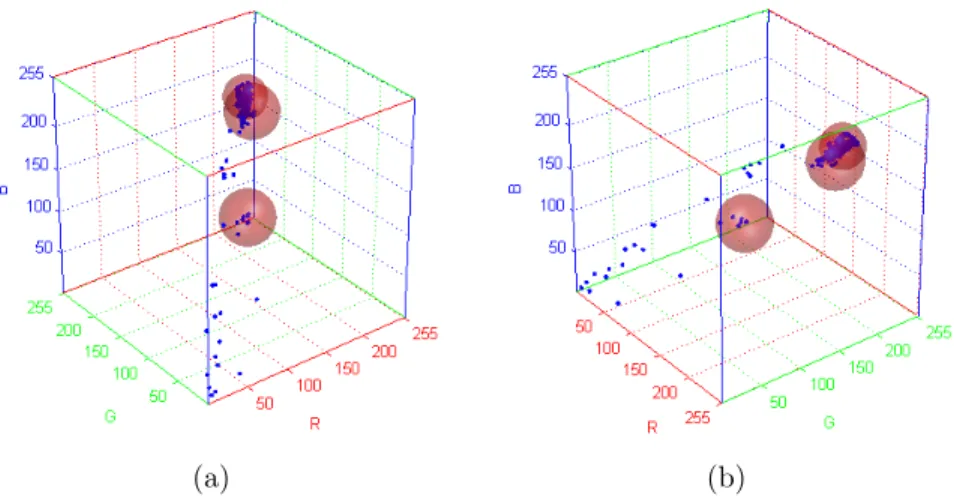
Stauffer and Grimson [44] presented a novel adaptive online background mixture model that can robustly deal with lighting changes, repetitive motions, clutter, introducing or removing objects from the scene and slowly moving objects. Their motivation was that a unimodal background model could not handle image ac-quisition noise, light change and multiple surfaces for a particular pixel at the same time. Thus, they used a mixture of Gaussian distributions to represent each pixel in the model. Due to its promising features, we implemented and integrated this model in our visual surveillance system.
In this model, the values of an individual pixel (e. g. scalars for gray values or vectors for color images) over time is considered as a “pixel process” and the recent history of each pixel, {X1, . . . , Xt}, is modeled by a mixture of K Gaussian
distributions. The probability of observing current pixel value then becomes:
P (Xt) = K
X
i=1
wi,t∗ η(Xt, µi,t, Σi,t) (3.4)
where wi,t is an estimate of the weight (what portion of the data is accounted
for this Gaussian) of the ith Gaussian (G
i,t) in the mixture at time t, µi,t is the
mean value of Gi,t and Σi,t is the covariance matrix of Gi,t and η is a Gaussian
probability density function: η(Xt, µ, Σ) = 1 (2π)n2 |Σ| 1 2 e−12(Xt−µt)TΣ −1(X t−µt) (3.5)
Decision on K depends on the available memory and computational power. Also, the covariance matrix is assumed to be of the following form for computa-tional efficiency:
Σk,t= α2kI (3.6)
which assumes that red, green, blue color components are independent and have the same variance.
The procedure for detecting foreground pixels is as follows. At the beginning of the system, the K Gaussian distributions for a pixel are initialized with pre-defined mean, high variance and low prior weight. When a new pixel is observed in the image sequence, to determine its type, its RGB vector is checked against the K Gaussians, until a match is found. A match is defined as a pixel value within γ (=2.5) standard deviation of a distribution. Next, the prior weights of the K distributions at time t, wk,t, are updated as follows:
wk,t = (1 − α)wk,t−1+ α(Mk,t) (3.7)
where α is the learning rate and Mk,t is 1 for the matching Gaussian distribution
and 0 for the remaining distributions. After this step the prior weights of the distributions are normalized and the parameters of the matching Gaussian are updated with the new observation as follows:
µt= (1 − ρ)µt−1+ ρ(Xt) (3.8)
σt2 = (1 − ρ)σt−12 + ρ(Xt− µt)T(Xt− µt) (3.9)
where
ρ = αη(Xt|µk, σk) (3.10)
If no match is found for the new observed pixel, the Gaussian distribution with the least probability is replace with a new distribution with the current pixel value as its mean value, an initially high variance and low prior weight.
In order to detect the type (foreground or background) of the new pixel, the K Gaussian distributions are sorted by the value of w/σ. This ordered list of distributions reflect the most probable backgrounds from top to bottom since by
(a) (b)
Figure 3.4: Two different views of a sample pixel processes (in blue) and corre-sponding Gaussian Distributions shown as alpha blended red spheres.
Equation 3.7 background pixel processes make the corresponding Gaussian distri-bution have larger prior weight and less variance. Then the first B distridistri-butions are chosen as the background model, where
B = argminb b X k=1 wk> T ! (3.11)
and T is the minimum portion of the pixel data that should be accounted for by the background. If a small value is chosen for T , the background is generally uni-modal. Figure 3.4 shows sample pixel processes and the Gaussian distributions as spheres covering these processes. The accumulated pixels define the background Gaussian distribution whereas scattered pixels are classified as foreground.
3.1.1.3 Temporal Differencing
Temporal differencing makes use of the pixel-wise difference between two or three consecutive frames in video imagery to extract moving regions. It is a highly adaptive approach to dynamic scene changes; however, it fails in extracting all relevant pixels of a foreground object especially when the object has uniform texture or moves slowly. When a foreground object stops moving, temporal dif-ferencing method fails in detecting a change between consecutive frames and loses
the object. Special supportive algorithms are required to detect stopped objects.
We implemented a two-frame temporal differencing method in our system. Let In(x) represent the gray-level intensity value at pixel position (x) and at time
instance n of video image sequence I which is in the range [0, 255]. The two-frame temporal differencing scheme suggests that a pixel is moving if it satisfies the following:
|In(x) − In−1(x)| > Tn(x) (3.12)
Hence, if an object has uniform colored regions, the Equation 3.12 fails to detect some of the pixels inside these regions even if the object moves. The per-pixel threshold, T , is initially set to a pre-determined value and later updated as follows:
Tn+1(x) = αTn(x) + (1 − α)(γ × |In(x) − In−1(x)|), x ∈ BG Tn(x), x ∈ F G (3.13)
The implementation of two-frame differencing can be accomplished by ex-ploiting the background subtraction method’s model update parameters shown in Equation 3.2. If α and β are set to zero, the background holds the image In−1
and background subtraction scheme becomes identical to two-frame differencing.
3.1.2
Pixel Level Post-Processing
The outputs of foreground region detection algorithms we explained in previous three sections generally contain noise and therefore are not appropriate for further processing without special post-processing. There are various factors that cause the noise in foreground detection such as:
• Camera noise: This is the noise caused by the camera’s image acquisition components. The intensity of a pixel that corresponds to an edge between two different colored objects in the scene may be set to one of the object’s color in one frame and to the other’s color in the next frame.
• Reflectance noise: When a source of light, for instance sun, moves it makes some parts in the background scene to reflect light. This phenomenon
makes the foreground detection algorithms fail and detect reflectance as foreground regions.
• Background colored object noise: Some parts of the objects may have the same color as the reference background behind them. This resemblance causes some of the algorithms to detect the corresponding pixels as non-foreground and objects to be segmented inaccurately.
• Shadows and sudden illumination change: Shadows cast on objects are detected as foreground by most of the detection algorithms. Also, sud-den illumination changes (e.g. turning on lights in a monitored room) makes the algorithms fail to detect actual foreground objects accurately.
Morphological operations, erosion and dilation[19], are applied to the fore-ground pixel map in order to remove noise that is caused by the first three of the items listed above. Our aim in applying these operations is removing noisy fore-ground pixels that do not correspond to actual forefore-ground regions (let us name them non-foreground noise, shortly NFN ) and to remove the noisy background pixels (non-background noise, shortly NBN ) near and inside object regions that are actually foreground pixels. Erosion, as its name implies, erodes one-unit thick boundary pixels of foreground regions. Dilation is the reverse of erosion and expands the foreground region boundaries with one-unit thick pixels. The subtle point in applying these morphological filters is deciding on the order and amounts of these operations. The order of these operations affects the quality and the amount affects both the quality and the computational complexity of noise removal.
For instance, if we apply dilation followed by erosion we cannot get rid of one-pixel thick isolated noise regions (N F N ) since the dilation operation would expand their boundaries with one pixel and the erosion will remove these extra pixels leaving the original noisy pixels. On the other hand, this order would successfully eliminate some of the non-background noise inside object regions. In case we apply these operations in reverse order, which is erosion followed by dilation, we would eliminate (N F N ) regions but this time we would not be able to close holes inside objects (N BN ).
(a) (b)
(c) (d)
Figure 3.5: Pixel level noise removal sample. (a) Estimated background image (b) Current image (c) Detected foreground regions before noise removal (d) Fore-ground regions after noise removal
After experimenting with different combinations of these operations, we have come up with the following sequence: two-levels of dilation followed by three-levels of erosion and finally one-level of dilation. The first dilation operation removes the holes (N BN ) in foreground objects that are detected as background and expands the regions’ boundaries. In the next step, three-levels of erosion removes the extra pixels on the region boundaries generated by the previous step and removes isolated noisy regions (N F N ). The last step, one level of dilation, is used to compensate the one-level extra effect of erosion. Figure 3.5 shows sample foreground regions before and after noise removal together with original image. Note that the resolution of actual image (320 x 240) is different than the one used for foreground detection (160 x 120).
Removal of shadow regions and detecting and adapting to sudden illumination changes require more advanced methods which are explained in the next section.
3.1.2.1 Shadow and Sudden Illumination Change Detection
Most of the foreground detection algorithms are susceptible to both shadows and sudden illumination changes which cause inaccurate foreground object segmenta-tion. Since later processing steps like object classification and tracking depend on the correctness of object segmentation, it is very important to cope with shadow and sudden illumination changes in smart surveillance systems.
In our system we used a shadow detection scheme which is inspired from the work presented in [21]. We make use of the fact that for pixels in shadow regions the RGB color vectors are in the same direction with the RGB color vectors of the corresponding background pixels with a little amount of deviation and the shadow pixel’s brightness value is less than the corresponding background pixel’s brightness. In order to define this formally, let Ix represent the RGB color
of a current image pixel at position x, and Bx represent the RGB color of the
corresponding background pixel. Furthermore, let ˆIx represent the vector that
start at the origin O (0, 0, 0) in RGB color space and end at point Ix, let ˆBx
be the vector for corresponding background pixel Bx and let dx represent the dot
product (·) between ˆIx and ˆBx. Figure 3.6 show these points and vectors in RGB
space. Our shadow detection scheme classifies a pixel that is part of the detected foreground as shadow if it satisfies:
dx = ˆ Ix Iˆx · Bˆx Bˆx < τ (3.14) and Iˆx < Bˆx (3.15)
where τ is a pre-defined threshold which close to one. Dot product is used to test whether ˆIx and ˆBx have the same direction or not. If the dot product (dx)
Figure 3.6: RGB vectors of current image pixel ˆIxand corresponding background
pixel ˆBx.
same direction with a little amount of deviation. The second check is performed to ensure that the brightness value of Ix is less than Bx. Figure 3.7 shows sample
foreground regions with shadows before and after shadow removal.
Besides shadow removal, sudden illumination change detection is also a re-quirement that needs to be met by a smart surveillance system to continue de-tecting and analyzing object behavior correctly. A global change may for instance occur due to sun being covered/uncovered by clouds in outdoor environments or due to turning lights on in an indoor environment. Both of these changes make a sudden brightness change in the scene which even adaptive background models cannot handle. Figure 3.8 shows sample frames before and after a sudden light change. Our method of sudden light change detection makes use of the same observation used in [37, 55], which is the fact that the sudden global light change causes the background models to classify a big proportion (≥ 50%) of the pixels in the scene as foreground. However, in some situations, where ordinary objects move very close to the camera, this assumption is too simplistic and fails. Thus, for the aim of distinguishing a global light change from large object motion, we make another check by exploiting the fact that in case of a global light change, the topology of the object edges in the scene does not change too much and the
(a) (b)
(c) (d)
Figure 3.7: Shadow removal sample. (a) Estimated background (b) Current image (c) Detected foreground pixels (shown as red) and shadow pixels (shown as green) (d) Foreground pixels after shadow pixels are removed
(a) (b)
Figure 3.8: Sudden light change sample. (a) The scene before sudden light change (b) The same scene after sudden light change
boundaries of the detected foreground regions do not correspond to actual edges in the scene whereas in case of large object motion the boundaries of the detected foreground regions correspond to the actual edges in the image.
In order to check whether the boundaries of the detected regions correspond to actual edges in the current image, we utilize the gradients of current image and the background image. The gradients are found by taking the brightness difference between consecutive pixels in the images in both horizontal and ver-tical directions. After the gradients are found both for background and current image, a threshold is applied and the output is converted to binary (where a one represents an edge). Then, the difference image of background and current image gradients is calculated to find only the edges that correspond to moving regions. Figure 3.9 shows sample gradient images for background and current images. Finally, the detected foreground region is eroded from outside towards inside till hitting an edge pixel in the gradient difference image. If the resulting foreground region is very small compared to the original, then this is an indication of a global light change, hence the background model is re-initiated with current and following few images. Wavelet images can also be used instead of gradients to distinguish a sudden global light change.
(a) (b)
(c) (d)
(e)
Figure 3.9: Detecting true light change. (a) Estimated reference background (b) Background’s gradient (c) Current image (d) Current image’s gradient (e) The gradient difference
(a) (b)
(c)
Figure 3.10: Connected component labeling sample. (a) Estimated background (b) Current image (c) Filtered foreground pixels and connected and labeled re-gions with bounding boxes
3.1.3
Detecting Connected Regions
After detecting foreground regions and applying post-processing operations to remove noise and shadow regions, the filtered foreground pixels are grouped into connected regions (blobs) and labeled by using a two-level connected component labeling algorithm presented in [19]. After finding individual blobs that corre-spond to objects, the bounding boxes of these regions are calculated. Figure 3.10 shows sample foreground regions before and after region connecting, labeling and boxing.