NETWORKS
A DISSERTATION
SUBMITTED TO THE DEPARTMENT OF ELECTRICAL AND ELECTRONICS
ENGINEERING
AND THE INSTITirrE OF ENGINEERING AND SCIENCE
OF BILKENT UNIVERSITY
IN PARTIAL FULFl LI.MENT OF THE REQUIREMENTS
FOR THE DEGREE OF
DOC'I OR OF PHILOSOPHY
BY
N ill at Ce m Oguz
lulv 1.995
5 i 0 5
'9 B S
PERFORMANCE OF TWO-LEVEL FORWARD ERROR
CORRECTION FOR LOST CELL RECOVERY IN ATM
NETWORKS
A DISSERTATION
SUBMITTED TO THE DEPARTMENT OF ELECTRICAL AND ELECTRONICS ENGINEERING
AND THE INSTITUTE OF ENGINEERING AND SCIENCE OF BILKENT UNIVERSITY
IN PARTIAL FULFILLMENT OF THE REQUIREMENTS FOR THE DEGREE OF
DOCTOR OF PHILOSOPHY
By
Nihat Cem Oğuz July 1995
___ _ /
0 38
Ι 3 9 Ί
I certify that I have read this thesis and that in my opinion it is fully adequate, in scope and in quality, as a dissertation for the degree of Doctor of Philosophy.
Ender Ayanoglu, Ph. D. (Supervisor)
I certify that I have read this thesis and that in my opinion it is fully qdequate, in scope and in quality, as a dissertation for the degree of Doctor of Philosophy.
Selim Aktiirk, Ph. D.
I certify that I have read this thesis and that in my opinion it is fully adequate, in scope and in quality, as a dissertation for the degree of Doctor of Philosophy.
dissertation for the degree of Doctor of Philosophy.
Erol Sezer, Ph. D.
I certify that I have read this thesis and that in my opinion it is fully adequate, in scope and in quality, as a dissertation lor the degree of Doctor of Philosophy.
Approved for the Institute of Engineering and Science:
Mehmet Baray, Ph.
P E R F O R M A N C E O F T W O -L E V E L F O R m R D E R R O R C O R R E C T IO N F O R L O S T CELL R E C O V E R Y IN A T M
N E T W O R K S Nihat Cem Oğuz
Ph. D . in Electrical and Electronics Engineering Supervisor:
Assoc. Prof. Dr. Ender Ayanogiu .July 1995
The major source of errors in Asynchronous Transfer Mode (ATM.) networks is expected to be buffer overflow during congestion, resulting in cell losses. The large ratio of the end-to-end propagation time for a typical connection to the cell transmission time makes lost cell recovery by means of retransmission- based error control techniques impractical especially for delay-sensitive high speed applications. As has been shown by many authors, forward error correction is a promising alternative since it can improve end-to-end reliability without requiring retransmissions. This thesis discusses the use of a two-level forward error correction scheme for virtual channel and virtual path connections in ATM networks. The performance of the scheme, which exploits erasure correcting simple and interleaved block codes simultaneously, is studied via both analyses
and simulations. For a single-node virtual channel connection, a novel and
accurate discrete-time analytical cell loss model is developed first. Based on this model, the reduction in the cell loss rate achieved by two-level coding is then investigated extensively via iterative computational methods. For the case
of a four-node, long-distance virtual channel connection that cannot tolerate any loss, the use of the two-level coding scheme in conjunction with an automatic repeat request mechanism is considered, and detailed simulations are made to quantify the improvement achieved in the delay-throughput performance. The results obtained indicate substantial performance improvements even for very high network loads provided that an appropriate coding technique is chosen according to the traffic characteristics. Typically, bursty traffic requires code interleaving be used for effective loss recovery whereas small-latency simple block codes suffice for random traffic. Two-level coding, which is shown to effectively combine the fast and burst loss recovery capabilities of the individual coding techniques, is attractive for traffic streams of unpredictable or time-varying characteristics.
K e y w o r d s : Asynchronous transfer mode (ATM ), forward error correction
(FEC), automatic repeat request (ARQ), lost cell recovery, cell loss process characterization.
A T M A Ğ L A R IN D A Y İT İK G Ö Z E K U R T A R IM I İÇ İN İK İ S E V İY E L İ İLERİ H A T A D Ü ZE L T İM İN İN B A Ş A R IM I
Nihat Cem Oğuz
Elektrik ve Elektronik Mühendisliği’nde Doktora Tez Yöneticisi:
Doç. Dr. Ender Ayanoğiu Temmuz 1995
Eşzamanstz Aktarım Modu (ATM) ağlarında ana hata kaynağının, göze yitimine
yol açan, sıkışmaya bağlı yastık taşımı olması beklenir. Göze gönderim zamanının tipik bir bağlantı için uçtan uca iletim gecikmesine oranla çok küçük olması nedeniyle, tekrar gönderime dayanan hata düzeltme teknikleri özellikle gecikmeye
duyarlı yüksek hızlı uygulamalar için uygun değildir. Pek çok araştırmacı
tarafından gösterildiği gibi, ileri hata düzeltimi, tekrar gönderime gerek duy madan uçtan uca güvenilirliği artırabilmesi nedeniyle, daha iyi bir seçenektir. Bu tez çalışmasında, iki seviydi bir ileri hata düzeltim yönteminin ATM ağlarındaki sanal kanal ve sanal yol bağlantıları için kullanımı tartışılmıştır. Basit ve biniştirilmiş blok kodların eşanlı kullanımına dayanan yöntemin başarımı, hem çözümleme hern de benzetim yoluyla araştırılmıştır. Tek düğümlü bir sanal kanal bağlantısı için, önce yeni ve doğru bir ayrık zaman göze yitim çözümleme modeli geliştirilmiştir. Ardından, bu model üzerinde dürümsel hesaplama yöntemleri kullanılarak, iki seviyeli kodlama yoluyla göze yitim olasılığında elde edilen azalma geniş biçimde araştırılmıştır. Göze yitimini kaldıramayan dört düğümlü bir uzun mesafe sanal kanal bağlantısı içinse, iki seviyeli kodlama yönteminin bir
otomatik tekrar gönderim mekanizması ile birlikte kullanılacağı düşünülmüş, ve bu şekilde uçtan uca toplam gecikmede elde edilen azalmayı ölçmek üzere ayrıntılı benzetimler yapılmıştır. Elde edilen sonuçlar, trafik karakteristiğine uygun bir kodlama tekniği kullanılması kaydıyla, çok yüksek ağ yükleri için bile önemli başarım iyileşmeleri sağlanabileceğini göstermiştir. Tipik olarak, rasgele trafik için az gecikmeli basit blok kodlar yeterli olurken, çoğuşuk trafik için etkin yitik göze kurtarımı, kod biniştirmesini gerektirmektedir. Bu iki kodlama tekniğinin hızlı ve çoğuşuk göze yitim kurtarım özelliklerini etkin biçimde birleştirdiği gösterilen iki seviyeli kodlama yöntemi ise, karakteristiği önceden belirlenemeyen veya zaman içinde değişme gösteren trafik için uygun bulunmuştur.
Anahtar sözcükler: Eşzamansız Aktarım Modu (ATM ), ileri hata dü
zeltimi (FEC), otomatik tekrar gönderim (ARQ)-, yitik göze kurtarımı, göze yitim süreç karakteri- zasyonu.
I would like to express my deepest gratitude to Dr. Ender Ayanoğlu for his invaluable guidance and suggestions during the development of this work, and also for that he encouraged me to participate in various distinguished international conferences from which I gained experience and motivation.
I am grateful to Dr. .Abdullah Atalar, chairman of our department, for his continuous moral support throughout my graduate study.
I would also like to thank to my friends Nail Akar and Ogan Ocah for their valuable technical support and discussions.
Finally, my sincere thanks are due to my parents and my wife Bengi for their love and patience. Bengi was so understanding even in my busiest moments, and undertook to look after Atıl, our lovely little son, night and day.
Contents
Abstract i
Özet iii
Acknowledgment v
Contents vi
List of Figures viii
List of Tables xi
1 Introduction 1
1.1 Asynchronous Transfer Mode ... 2
1.2 Lost Cell Recovery Techniciues for ATM 5 1.3 FEC for ATM in the L ite ra tu re ... 6
1.4 Objectives and Outline of the T h e s i s ... . 8
2 Two-Level FEC for ATM 13 2.1 Two-Level FEC S c h e m e ... 13
2.2 Use of Two-Level FEC for VC and V P ... 17
2.2.1 Two-Level FEC for a VC C on n ection ... 18
2.2.2 Two-Level FEC for a VP C on n ection ... 20
3 Analytical Framework 23 3.1 Input Traffic M o d e l... 24
3.2.2 Computation of the CLR: No Column C o d i n g ... 30
3.2.3 Computation of the CLR; With Column C o d in g ... 32
3.3 Analysis for the Optimal D e c o d e r ... 34
3.3.1 Reduced-Complexity Cell Loss M o d e l... 36
3.3.2 Quantification of the C L R ... 41
3.A Computation of the GLM Parameters... 43
4 Performance of Two-Level FEC 46 4.1 Row-Only Coding R e s u lt s ... 48
4.2 Constrained Decoding Case ... .51
4.2.1 Column-Only Coding Results 51 4.2.2 .Joint Coding R e s u lts ... 53
4.3 Optimal Decoding Case ... 57
4.3.1 Column-Only Coding R e s u lt s ... 57
4.3.2 .Joint Coding R e s u lts ... 59
4.4 Discussion of R e s u lt s ... 62
5 Performance of Hybrid Two-Level FEC and ARQ 65 5.1 Hybrid Two-I^vel FEC and ARQ S c h e m e ..., . . 66
5.2 Simulation M o d e l ... 69
5.3 Results and D iscu ssion ... 71
5.3.1 Results for the Dedicated Queueing C a s e ... 72
5.3.2 Results for the Shared Queueing C a s e ... 73
5.3.3 Concluding R e m a rk s ... 74
6 Summary and Conclusions 78
Bibliography 81
Vita 84
List of Figures
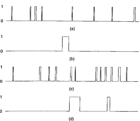
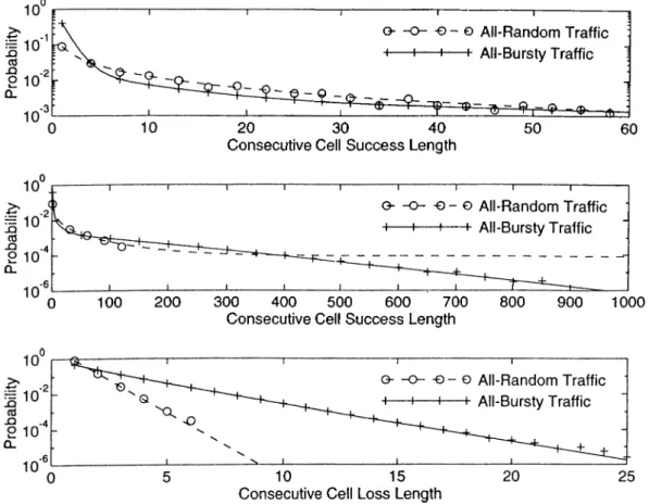
2.1 2.2 2.3 3.1 3.2 3.3 3.4 3.0 3.6 3.7 4.1Two-level coding scheme... 14 Consecutive loss of 18 cells... 19 Cell loss detection mechanism for the case of two-level F’EC for VP. 21 Output-buffered /V-to-l ATiM multiplexer... 24 MC model of an individual source... 24 Some typical cell stream realizations over 200-slot periods for the following offered loads and clustering coefficients: (a) pi = 0.05, c = 1.2; (b) Pi = 0.05, c = 1.9; (c) pi = 0.1, c = 1.2; and (d) Pi = 0.1, c = 1.9. Celts generated consecutively are represented by a single pulse of height 1 and width proportional to the number of celts in the batch... 26 Modification of the state transition probabilities during the de composition of a potentially “ bad” state into tagged cell “success” and “loss” states, where it is assumed that u' > B — b... 29 The Gilbert loss model for the row loss process... 32 The consecutive cell success and loss length distributions for
diversely random and bursty traffic scenarios. 36
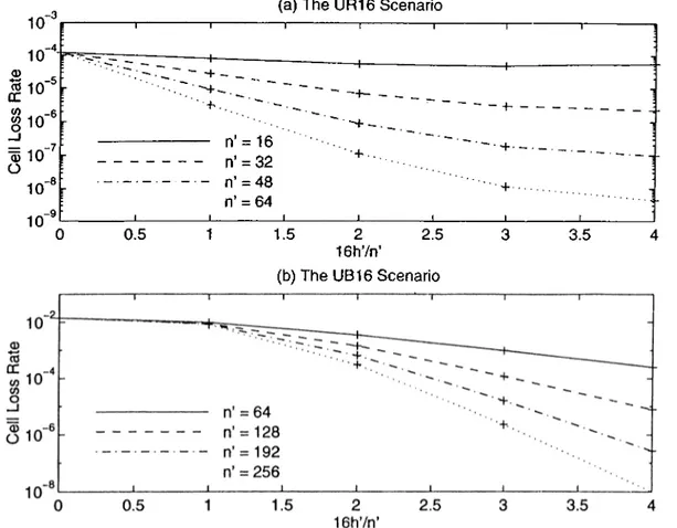
An alternative MC model for the tagged cell loss process... 37 Effects of n and h/n on the row-only coding performance for the UR16 and UB16 scenarios, where n is the row size and h is the number of parity cells in a row... 48
size. The smallest row sizes that guarantee the CLRs of 10“ ^, 10“ ^, 10“ ^, and 10~^ are also indicated for each traffic scenario... .50 4.3 Effects of n' and h'In' on the performance of column-only coding
with the constrained decoder for the UR16 and UB16 scenarios, where n' is the column size, h' is the number of parity cells in a column. The row size n is fixed as 16 for both scenarios... 52 4.4 Effects of h and h' on the performance of joint coding with the
constrained decoder for the UR16 and UB16 scenarios, where h and
h' are the numbers of parity cells per row and column, respectively.
The row size n is fixed as 16 for both scenarios, and the column size n' is 64 for the UR16 scenario and 256 for the UB16 scenario. .54
4.5 Coding performance with the constrained decoder for the UR16
and UB16 scenarios as a function of the load. Different loads are obtained by keeping pt = pu and varying both. The legend NC corresponds to “no coding,” ROC to “ the (64,16) code,” COCl to “the [16,(64,16)] code,” COC2 to “the [16,(256,64)] code,” JCl to “the [(16,1), (64,12)] code,” and JC2 to “the [(16,1), (256,48)] code.” The discrete points are the results obtained by event-driven simulations... 55 4.6 The constant-CLR curves for [?i, (n', n'/4)] column-only coding on
the logarithmic njz'-plane for the BB15 scenario, where n and n' are the row and column sizes, respectively. The integer valued (n ,n ') pairs which minimize the decoding latency and complexity while guaranteeing the CLRs of 10“ ^, 10“ ®, lO“ ’^, and 10“ ^ are indicated separately... 58 4.7 Comparison of [(n, n /8), (n', n'/S)] Jobit and [n, (n', ii'/d)]
column-only coding techniques via constant-CLR curves on the logarithmic nn'-plane for the BB15 scenario, where n and n' are the row and column sizes, respectively... 60
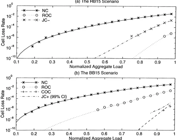
4.8 Coding performance with the optimal decoder for the RB15 and BB15 scenarios as a function of the load. Different loads are obtained by keeping pt — 0.075 unchanged and varying /?„
only. The legend
NC
corresponds to “no coding,”ROC
to “the(256,64) code,”
COC
to “the [4,(256,64)] code,”JC+
to “the[(256,36), (8,1)1 code,” and
JC-
to the same joint code with rowdecoding only. The
JC+
results are obtained by 6 independentanalysis-driven simulation runs with 10^ tagged cells generated in each run. The discrete points are the results obtained by event- driven simulations... 61 5.1 Two-level FEC over cells and PDUs: an alternative illustration of
the coding matri.x of Figure 2.1... 66 5.2 ¿-node VC model... 69
5.3 Performance of the hybrid scheme for the dedicated output
ciueueing case. The numbers of information-bearing cells in a PDU,
N c, and information-bearing PDUs in a coding block, Np, are
fixed as 16 and 256, respectively. The numbers of parity cells in a PDU, M e, and parity PDUs in a coding block, Mp, are indicated in the format ( Mc , Mp ) . Averages are computed over 512 coding blocks... 76
5.4 Performance of the hybrid scheme for the shared output ejueueing
case. The numbers of information-bearing cells in a PDU, Nc, and information-bearing PDUs in a coding block, Np, are fixed as 16 and 256, respectively. The numbers of parity cells in a PDU,
Me , and parity PDUs in a coding block, Mp, are indicated in the
1.1 Service classes in ATM and associated AAL protocol types... 3 1.2 Correspondence between the thesis and the literature... 11
4.1 The traffic scenarios and the corresponding CLRs for the no coding
case. The traffic parameters pt, pu, ct, and are the normalized loads offered by and the clustering coefficients for the tagged and untagged sources, respectively... 47
Chapter 1
Introduction
Today, there is an ever increasing demand for new kinds of telecommunication services from both residential and business subscribers. High definition TV, video conferencing, high-speed data transfer, videopliony, video library, home education, and video on demand are among the services that are expected to be in wide use in the near future. Owing to the recent advances in semiconductor and optical technologies, and the related progress in system concepts, a single high speed communication network, often referred to as Broadband Integrated Services
Digital Network (B-ISDN), which can support all these services efficiently in
a unified manner is now becoming a reality [16], [21]. A switching technique called Asynchronous Transfer Mode (ATM) has been selected by ITU-T^ the International Technological Union-Telecommunications Section, as the basis for B-ISDN [10].
Although ATM is basically a packet switching technique, the B-ISDN/.ATM has several features distinguishing it from conventional packet-switched networks. In this chapter, we first describe ATM briefly as a transport discipline for B-ISDN. This thesis contributes to “packet loss recovery” in ATM networks, and we discuss this issue next. Finally, after summarizing the related work in the literature, we motivate the packet loss recovery scheme we consider for ATM networks, and
TTU-T was formerly known as CCITT, the International Consultative Committee for Telegraph and Telephone.
briefly discuss our contributions.
1.1
Asynchronous Transfer Mode
In ATM, the packet size is small and fixed. These packets, called cells in the ATM terminology, are composed of 53 octets, 5 octets for the header and 48 octets for the information field. Although using variable-size packets in general yields higher transmission bandwidth efficiency, this choice for ATM has been made based on the following rationale [16], [21]. First, fixed-size packets enable the use of fast, hard ware-based switches that can support high-speed services. Second, with small packets, it is in general easier to control end-to-end delay for real-time services. In fact, the impact of packetization delay on the quality of interactive voice services is the particular reason behind choosing an information field as small as 48 octets^.
An ATM network conforms to a layered protocol reference model [16], [21]. At the bottom of this reference model, there is the physical layer which provides a cell pipe to the second layer, called the ATM layer. The ATM layer is simply responsible for transporting, switching, and queueing cells within the network. The third layer is the ATM Adaptation Layer (AAL), and its primary function is to translate the service-specific nature of user data into a cell stream at the source site, and to do the converse at the destination site.
Unlike the case in conventional data networks, there is no link-by-link flow control in ATM because small cells and high data transmission rates limit the processing time per cell at the nodes [16]. Also because optical fibers have very low error rates, there is no link-by-link error control, either. Instead, these
^In interactive voice communications, an overall network delay larger than 20-.30 ms becomes troublesome, and requires the use of echo cancelers. Considering typical propagation and queueing delays, a packetization delay of about 5 ms is found to avoid echo problem for most voice connections. Since 64 kbps digital voice data is packetized into 32 octets in 5 ms, this suggests the use of a 32-octet information field as proposed by Europeans. On the other hand, because echo cancelers already exist in USA, Americans have proposed to use a 64-octet information field in order to improve transmission bandwidth efficiency. 48 octets has been selected as a compromise between the two.
Chapter 1. Introduction
Class A 1 Class B Class C 1 Class D
Timing Relation required not required
Bit Rate constant variable
Connection Mode connection-oriented connectionless
Examples Digital Telephone Service Compressed Audio and Video Data Transfer, Signalling Switched Multimegabit Data Services AAL Type 1 2 3/4, 5 3/4
T able 1.1: Service classes in ATM and associated AAL protocol types.
functions are shifted to the network boundary, and if necessary, performed by AAL or higher layer protocols at the user-network interface.
ATM operates in a connection-oriented mode, and two types of logical
connections are supported by the ATM layer [16], [21]. The basic type of
connection is the Virtual Channel (VC) connection provided to the users for end- to-end data transport. The second one is the Virtual Path (VP) connection used internal to the network maiidy for the purpose of reduced switching complexity. A VP can be viewed as a bundle of VCs which are switched together along a common path through the network. Each cell has a VC and a VP Identifier (VCI and VPI) in its header which respectively indicate the VC and the VP that the cell belongs to. At each node along a VP, cells are routed based only on their VPIs (VP switching). This reduces the complexity of routing decisions as the network deals with fewer, aggregated entities, i.e., VPs instead of individual VCs. Yet, a VC can consist of multiple VPs concatenated to form the end-to- end connection, and the individual VCs have to be switched similarly at the VP terminating and originating nodes (VC switching).
In ATM, services are divided into four classes, and different AAL protocols are employed to support each class successfully [16], [21]. This classification is made according to three basic parameters: timing relation between the source and the destination, bit rate characteristics, and connection mode. Classical digital telephone service is an example for constant bit rate services that require timing
relation between the source and the destination, and the AAL type 1 protocol absorbs the delay jitter due to variable queueing delays for this service. Table 1.1 summarizes other service classes and examples, and indicates the associated A.AL
protocol types. Note that, although ATM is tailored to connection-oriented
services, transportation of connectionless traffic by the AAL type .3/4 protocols is also considered.
Like conventional packet-switched networks, an ATM network suffers from two sources of errors: imperfections of the physical transmission media, resulting in bit errors; and, buffer overflow during congestion, resulting in cell losses. Some precautions against bit errors have already been taken in ATM [16], [21]. For example, in the AAL type 2 and 3/4 protocols. 10 bits of the information field is reserved for a Cyclic Redundancy Check (CRC) code which can detect errors and correct up to two correlated bit errors in the information payload. Similarly, one octet of the cell header is an 8-bit CRC code which can correct single-bit errors and detect double-bit errors in the header. This code is used by the physical layer protocols to minimize switching errors, i.e., cell loss and insertion due to misrouting of cells with corrxipted headers.
On the other hand, no dynamic actions are defined against buffer overflow
in ATM [16]. Instead, preventive congestion control methods are employed
to minimize the probability of this event. In the network design phase,
physical allocation of transmission resources and dimensioning of buffers are made according to the expected traffic flow characteristics. In the network operation phase, sophisticated connection admission control protocols reject connection requests that would increase the probability of congestion too much if admitted. Once a connection is established, traffic policing mechanisms are used to ensure that the user does not overwhelm the allocated resources. Despite all these efforts, there will be congestion mainly because there is no link-by-link flow control in ATM [16]. Furthermore, due to very low bit error rates of optical fibers, congestion losses are expected to be the dominant source of errors in ATM networks [14]. Recovery of lost cells for services that cannot tolerate loss is the responsibility of the AAL protocols.
Chapter 1. Introduction
1.2
Lost Cell Recovery Techniques for A TM
There are two alternative error control techniques for packet-switched net works [20]. The first one is based on using error detecting codes and packet retransmissions by the source upon destination’s requests, and hence, requires cooperation o f the source and the destination. This technique is called automatic repeat request, or ARQ. There are various .ARQ protocols, some tailored to simplicity (e.g., stop-and-wait ARQ) and some tailored to efficient link utilization (e.g., go-back-A' and selective-repeat ARQ). Unlike .-\RQ, the second alternative is an open-loop technique which does not require cooperation of the end points. This technique, called Forward Error Correction (F’ EC), is based on using error correcting codes so that the destination itself can recover from errors without requiring packet retransmissions. The cost of this recovery capability is the additional transmission overhead associated with using error correcting codes instead of error detecting codes. Typically, the transmission overhead has to be doubled if errors are to be corrected rather than just being detected [7].
When ARQ and FEC are considered as candidate techniques for lost cell recovery in a wide area ATM network, two perspectives that favor the use of FEC arise [1], [14]. These are the perspectives of loss-sensitive services with and without real-time constraints. Here, ARQ suffers from the same problems as those encountered in satellite and deep-space communications, where FEC is widely used [4]. These problems are the large end-to-end propagation delay and the large ratio o f propagation delay to cell transmission time.
The propagation speed through a guided medium such as the optical fiber or the coaxial cable is approximately 2 x 10*” m /s [20]. Thus, the end-to-end propagation delay for a transcontinental or intercontinental connection of length, say, 10000 km is about -50 ms, and each retransmission increases the cell delay by more than the round-trip propagation delay, 100 ms. Many high-speed services such as real-time video, interactive computing, and distributed processing cannot tolerate that large retransmission delays. Therefore, FEC is definitely more appropriate than ARQ for services with stringent delay requirements.
One of the standardized data transmission rates in ATM is 155.52 Mbps [16], [21]. It takes about 2.7 ps to transmit a 53-octet cell at this rate, and this time is equivalent to the end-to-end propagation delay on a link of length 550 meters only. Therefore, even if the source utilizes only 10% of the 155.52 Mbps .ATM transmission capacity, it can transmit more than 200 cells over a 550 km-long connection before it receives a signal from the destination about loss or success of the first cell it has transmitted. For longer connections, the number of cells in round-trip propagation may reach several thousands. This results in too high an ARQ protocol complexity as the source and the destination have to cooperate intensively in successful and in-sequence delivery of that many outstanding cells. FEC, not requiring source-destination cooperation, is preferable also for delay- tolerant services.
On the other hand, there are services which tolerate no loss at all. An example is file transfer. Since F'EC is not a complete solution against cell losses in itself, retransmissions are inevitable for such services. In this case, ARQ can be used alone, or accompanied by FEC. The latter approach, i.e., hybrid FEC and ARQ, is advantageous because, by requiring fewer number of retransmissions as compared to ARQ alone, it not only reduces delay, thus improving the quality of service, but also can make more efficient use of the network resources.
1.3
FEC for A T M in the Literature
In 1975, Maxemchuk suggested the use of FEC to reduce the end-to-end delay for datagram-based services [13]. In a similar manner, FEC has been studied to improve reliability without increasing packet delay in high-speed networks, in particular ATM networks [1], [2], [5], [6], [11], [14], [15], [18], [19], [23], [24].
Since cell loss due to buffer overflow during congestion is expected to be the major source of errors in an ATM network as stated before, the common objective of all these studies is to recover lost cells. The basic idea in achieving this objective is to transmit separate parity cells along with the information-bearing ones. The parity cells are generated by using linear block coding techniques, and
Chapter 1. Introduction
the destination can recover all the lost cells in a block provided that sufficiently many cells of that block arrive successfully at the destination. In return for this recovery capability, the parity cells increase the network load, and in turn, the cell loss rate before decoding. Therefore, the code should introduce a reasonable parity overhead, and be still sufficiently powerful to overcome the opposite effect of load increase so that a significant net gain is achieved. Since lost cells can be identified at the destination by some means, usually by means of sequence numbers, the codes employed are commonly erasure correcting codes. These codes are more efficient than error correcting codes as they require typically half the parity overhead to recover the same number of losses per block [7].
The FEC schemes studied in the literature fall into two categories with respect to the particular block coding techniques employed. Some of the previous work focused on using codes over consecutive cells (simple block codes) [5], [6], [14], [18], [19], [2-3], [24], and some on using codes over equidistant cells (interleaved block codes) [1], [2], [11], [15].
Biersack carried out extensive simulations for the case of using simple block codes for a cell stream derived from a real, compressed motion picture interfering at a node with its time-shifted replicas as well as bursty streams [5]. In [6], he extended this study by using a simple analytical cell loss process characterization obtained via simulations. The results of [5] and [6] rev'eal that simple block coding can be quite effective for compressed video traffic, whereas it is inadequate for bursty traffic.
McAuley discussed various aspects of using FEC in broadband communica tions, and described an erasure correcting Reed-Solomon coder based system for ATM networks [14].
Shacham analyzed single-parity and some suboptimal multiple-parity block codes under the independent cell loss assumption [18]. He also considered the use of buffer management techniques to disperse cell losses, and hence, to improve the coding performance. Later, Shacham and McKenney extended this study, and showed by simulations that the independent cell loss assumption in the analysis may yield overly optimistic results [19]. They also considered but did not analyze
a simple form of the FEC scheme we study in this thesis.
Zhang and Sarkies analyzed the performance of simple block coding for a VP connection [23], [24]. They modeled the VP as a tandem ciueueing network, and assumed interrupted and Markov modulated Bernoulli cell sources. As a basis for the analysis in this context, they developed an approximate Markov Chain (M C) model estimating the end-to-end cell loss behavior.
Ayanoglu et al. discussed incorporation of FEC into high-speed protocols [1]. In particular, they considered a hybrid F'EC and ARQ scheme for minimizing the A.AL Protocol Data Unit (PDU) retransmissions. The AAL PDUs are variable length user data units which are segmented into cells at the source site and reassembled at the destination site. The PDUs with missing cells are assumed to be lost, and retransmitted by the source. The FEC scheme they considered is based on transmitting separate parity PDUs along with the information bearing ones, and lost PDUs can be recovered without requiring retransmissions if sufficiently many PDUs in the associated block arrive without any missing cells. Later, this scheme was shown to provide significant reductions in PDU delays by an approximate analysis for a multi-node VC connection [2].
Kitarni and Tokizawa analyzed interleaved block codes under the independent cell loss assumption [11]. Later, Ohta and Kitami improved this analysis by using the Gilbert loss model, and dealt mainly with the practical issues of end-to-end erasure channel realization for a VP connection [15].
1.4
Objectives and Outline of the Thesis
Our principal motivation in this work is the fact that the cell loss process characteristics should be taken into account in designing an effective FEC scheme for ATM networks. Simple block coding is expected to be effective when losses are dispersed evenly over the cell stream (e.g., are random) [7]. However, due to the memory of the buffer overflow process, cell losses will be correlated in time, in other words, will occur in bursts. Code interleaving then appears preferable to simple block coding since it is a simple and effective way to recover from
Chapter 1. Introduction
burst losses [7]. However, the burstiness of cell losses strongly depends on the traffic characteristics. It is in general known that the more bursty the traffic is, the more bursty the cell loss process will be [5], [6]. Consequently, there may be situations where simple block coding can perform quite well with smalt to moderate block lengths, thus enabling fast recoveries for services with stringent delay requirements. For e.xample, this is the case for compressed video traihc as the results of [5] and [6] indicate. This thesis considers the use of a two-level
FEC scheme which exploits simple and interleaved block codes simultaneously
to take the combined advantage of fast and burst loss recovery capabilities of the individual coding techniques.
Our main objective is to study the effect of traffic characteristics on the coding performance, and to demonstrate the usefulness of FEC, in particular two-level FEC. For this purpose, we carry out an extensive performance study comparing two-level FEC with the individual coding techniques for various traffic scenarios and network models.
For services with stringent delay requirements, we focus on a single-node VC connection. Modeling the node by an output-buffered ATM multiplexer, we quantify the reduction in the cell loss rate achieved by using FEC. This quantification is based on a novel and accurate discrete-time analytical cell loss model. We develop the model in two stages, and associated with each stage, carry out detailed performance analyses for diversely random and bursty traffic scenarios.
In the first stage, we construct an exact MC model for the output buffer occupancy with the traffic burstiness information explicitly incorporated into the model. Although the exact MC can be very large for realistic multiplexer parameters, it captures the bursty nature of cell losses precisely. Furthermore, by using simple source models, it can be made sparse. Therefore, by using iterative methods, we are able to compute the cell loss rate accurately for the uncoded and coded cases especially under bursty traffic conditions. Comparisons of the computational results with those obtained by simulations indicate that the exact MC model is quite accurate.
Because of the large size of the exact MC, the complexity of the iterative cell loss rate computations is too high with respect to both time and memory requirements. Consequently, the first stage analysis suffers from some practical limitations. That is, simple block codes are restricted to small block lengths, and more importantly, interleaved block and two-level codes are restricted
to be decoded suboptimally. In the second stage, we aim to overcome this
computational bottleneck. For this purpose, we introduce a novel MC cell loss model which is constructed based on the exact MC with reasonable computational burden. Unlike the exact MC, the new one is by definition highly sparse as there are only two next states reachable from any given state in just one transition. This reduces the complexity of iterative cell loss rate computations significantly. Therefore, in the second stage, we are able to study various codes without any practical restriction. Similar comparisons with simulation results indicate that the second stage analysis, and hence the new MC cell loss model, which we refer to as reduced-complexity M C model, are quite accurate under arbitrary traffic conditions.
The results of these performance analyses can be summarized as follows. First of all, FEC can effectively reduce the cell loss rate by several orders of magnitude over a wide range of network load and traffic characteristics. However, this requires the use of an appropriate coding technique chosen according to the traffic characteristics. The traffic stream for which FEC is desired is found to have a more important role in this regard as compared to interfering traffic. Typically, simple block coding can be quite fast and effective for a traffic stream of random nature. For a bursty traffic stream, however, the cell loss process is more bursty, and it becomes inadequate unless the block length is very large. In this case, code interleaving is a better FEC technique to use. Two-level FEC, combining the fast and burst loss recovery capabilities of the individual coding techniques, relaxes the need for a priori knowledge of the traffic stream. It allows fast loss recoveries if the traffic is random, and burst loss recoveries if the traffic is bursty. Therefore, it is attractive especially for traffic streams of unpredictable characteristics. Since a VP connection aggregates several individual VC traffic
Chapter 1. Introduction 11
Literature Thesis
Simple block and interleaved block codes studied separately.
Simultaneous use of the two studied in detail, shown to be useful.
Two-level FEC based on single-parity codes mentioned [19].
Two-level FEC based on optimal multiple- parity codes discussed in detail (Ch. 2). Approximate treatment of traffic burstiness
in cell loss process characterization [23], [24].
Exact treatment: explicit incorporation of the traffic burstiness information into the exact MC model (Ch. 3).
Idea of the exact MC model exploited [8]; but not completely described for discrete time systems with multiple sources.
idea applied to a discrete-time system with multiple sources, the output-buffered ATM multiplexer (Ch. 3); used extensively (Ch. 4). The Gilbert loss model used [15]; reflects cell
loss behavior correctly, cell success behavior incorrectly.
Reduced-complexity MC model; reflects cell loss and success behaviors correctly (Ch. 3). E]ffect of traffic characteristics on the per
formance of simple block coding technique studied [5], [6].
Simple block, interleaved block, and two-level coding techniques studied and compared as a complement in this regard (Ch. 4).
Hybrid FEC and ARQ studied by an approx imate analysis for a multi-node VC connec tion; coding over PDUs considered [2].
Detailed simulation study carried out as a complement; coding within PDUs and coding over PDUs considered to be used individually eis well as simultaneously (Ch. 5).
T able 1.2: Correspondence between the thesis and the literature.
streams of diverse characteristics and delay requirements, the use of two-level FEC is promising for a VP connection.
Motivated by services with stringent loss requirements, we also consider the use of two-level FEC in conjunction with ARQ. In this context,, focusing on a four-node VC connection over a wide geographical area, we carry out a detailed simulation study to quantify the improvement in the delay-throughput performance achieved by using FEC under rather bursty traffic conditions. The results obtained indicate that significant savings in retransmissions are achievable
even for very high network loads. In particular, two-level FEC is found to
combine, or add, the gains of individual coding techniques.
In Table 1.2, the correspondence between the thesis and the previous work in the literature is summarized.
FEC scheme in detail. VVe also address some practical issues related with erasure channel realization for VC and VP connections in Chapter 2. In Chapter 3, we describe the analytical performance model, i.e., the exact and reduced-complexity MC models, and the iterative methods we use to compute the cell loss rate. The results of the performance analyses are introduced and discussed thoroughly in Chapter 4. Chapter 5 introduces the simulation model for the hybrid scheme, and discusses the results obtained. We present concluding remarks in Chapter 6.
Chapter 2
Two-Level FEC for A T M
The two-level code we consider is a product code which has two independent dimensions or levels of coding [7]. A simple form of these codes is used in ASCII transmission to be able to detect burst as well as scattered bit errors [20]. Each 7-bit ASCII character is appended a parity check bit so that a character with odd number of bit errors can be detected (first level of coding). In addition to this, an 8-bit parity check character is appended to every group of rn ~ 1 characters so that eight consecutive bit errors and many other bit error patterns in an m- character block can be detected (second level of coding). Here, we exploit this idea to recover from burst as well as random cell losses in an ATM network.
2.1
Two-Level FEC Scheme
The two-level coding scheme is shown in Figure 2.1. The information-bearing cells (i-cells) generated at the source are assumed to fill a k' x k matrix row-wise which is encoded as follows. First, each row of k i-cells is appended h parity cells (p- cells), which are generated by erasure correcting linear block coding techniciues. Then, each column of k' cells of the resulting k' x n matrix is similarly appended
h' parity cells (p'- and p"-cells respectively for i- and p-cell columns) to form an
overall n' x n coding matrix, where n = k h and n' = k' -f h'. Since both row
and column codes are linear, the p"-cells can be generated according to either row
time p' p' P' p' p' p' p' P' • p' P' p' p' p" p" p" p" p" p" p" p" p"
F igu re 2.1; Two-level coding scheme.
11
h'
or column coding rules, and be used accordingly. Observe that, by filling in and sending out the coding matrix row-wise as indicated in Figure 2.1, row coding corresponds to simple block coding, and column coding to code interleaving.
Similar to the common approach in the literature, we assume that the lost cells can be identified at the destination. This end-to-end erasure channel assumption enables the use of optimal, maximum-distance separable erasure correcting codes that can recover as many erased symbols as there are parit}' symbols in a block [7]. Such codes can be found, for example, in the class of well-known BCH codes, in particular Reed-Solomon codes. Some aspects of using these codes for the purpose of lost cell recovery are as follows. The encoding and decoding operations both
Chapter 2. Two-Level FEC for ATM
15
involve manipulation of the payloads of cells m bits taken at a time where rn depends on the block length*. If the payload length in bits is not divisible by m, sufficiently many zeros are assumed to be padded to make it divisible. The encoding operation has a multiply-and-add nature which means that all the parity cells can be constructed in parallel without any encoding delay as the associated information-bearing cells are being transmitted. Typically, there will be some post-processing in decoding when there are losses to recover. The complexity associated with this post-processing, i.e., decoding complexity increases with the block length^.
In this thesis, we assume that both rows and columns of the coding matrix are encoded optimally as just described so that up to h losses per row and h' per column can be recovered. With regard to decoding, we consider three particular decoders which are described below.
The simplest and perhaps the most intuitive one of the three first decodes rows one-by-one as they arrive, and then columns similarly for subsequent possible recoveries. Such a decoder, which we refer to as single-trace decoder, can recover up to h'n + k'h losses out of nn' provided that they are distributed over the coding matrix appropriately. In particular, the loss of h'n consecutive cells, or the complete loss of h' rows can be compensated for by column decoding if the number of losses in other rows does not exceed h per row. Since column recoveries may enable new row recoveries, and vice versa, still belter performance is achievable. The optimal decoder is the one that keeps tracing rows and columns successively until no more possible recoveries are left. Unlike these two decoders, the third one performs column decoding in a rather constrained manner. That is, it treats unrecoverable rows with more than h losses as being “lost,” and ignores the successful cells of such lost rows. If the number of lost rows in a coding matrix does not exceed h', it reconstructs the whole matrix. Otherwise, it does not act
fHere, an m-bit partition of the payload represents a symbol in GF{2"'), and 2"’ > n is required where n is the block length [7].
^In [7], various fast decoding algorithms are described for BCH and Reed-Solomon codes. With these algorithms, the asymptotic complexity of decoding is 0(nlog2n) for BCH codes, and is at most O(nlog^n) (very nearly O(nlogn)) for Reed-vSolomon codes, where n is the block length. These complexity figures indicate the number of multiplications in GF(2"').
at all, and all the recoveries will be those achieved by decoding rows only. Due to this on-ofF action, this decoder, which we refer to as constrained decoder, should be expected to have poorer performance as compared even to the single-trace decoder. Nevertheless, our results indicate that it can be appreciably effective as will be discussed in Chapters 4 and 5.
An important issue with regard to implementation of the three decoders described above is as follows. Observe that the destination has to have a buffer of capacity nn' cells to store incoming cells of a coding matrix since they will be used during post-processing, or decoding, in the case of losses. Now, while the decoder, any one of the three, is busy with post-processing of a coding matrix, a cell of the next coding matrix may arrive. Depending on the post-processing time and the instantaneous cell arrival rate, the arrival of multiple cells is even possible. Obviously, these cells must be stored until the decoder finishes with the current coding matrix. This means that an additional buffer space is required at the destination. Since the optimal decoder may go through more number of row and column decoding processes depending on the loss pattern, it requires a larger additional buffer as compared to the constrained and single-trace decoders. A simple solution here may be to employ two buffers, each of capacity nn' cells, at the destination. Then, while the decoder is post-processing a coding matrix that is stored in one of the buffers (foreground buffer), the cells of the next coding matrix can be stored in the other buffer (background buffer). Upon finishing with the current coding matrix, it can simply dump the contents of the background buffer to the foreground buffer, or can toggle between the two buffers treating them as foreground and background appropriately for successive coding matrices. However, if nn' is large, the additional buffer cost in this solution may be too high. Also, it seems quite pessimistic to expect that this much additional memory will really be required. Therefore, a compromise can be made. For example, one can content with an additional buffer of capacity n cells in which all the cells in the first row of the next coding matrix can be stored. In this case, instead of the single-trace and optimal decoders, we can consider a best-effort decoder which performs as much row and column traces as possible until the additional
Chapter 2. Two-Level FEC for ATM 17
buffer overflows. The performance of this decoder will then vary in time between those of the single-trace and optimal decoders depending on how fast this buffer overflows. In this thesis, we particularly focus on studying the performances of the constrained and optimal decoders, and assume that such a buffer overflow problem never arises.
So far, we have discussed “optimal two-level encoding and decoding” for a given set of parameters n, k, n', and k'. Obviously, this does not mean that the two-level code itself is optimal for the given overall block length nn' and code rate kk'/nn'. The optimal code here is a simple block code with kk' information bearing cells and nn' — kk' parity cells which can recover any pattern of nn' — kk' lost cells out of nn'. However, this code suffers from higher decoding complexity as compared to the two-level code since its block length is larger. Using the two- level code instead of the optimal one is eciuivalent to trading decoding flexibility for reduced decoding complexity. Nevertheless, note that the optimal decoder described above provides a partial compensation for the loss of decoding flexibility as it can recover many patterns of more than nn' — kk' lost cells. Also, the average decoding latency, i.e., the average time that a lost cell waits for a possible recovery, is smaller for the the two-level code than for the optimal one. This is justified by the fact that a row can be recovered immediately upon accumulation of sufflciently many successful cells of that row without waiting for the end of the coding matrix. Although this advantage is blurred by the requirement of in- secpience delivery of cells to the destination, it is still quite useful as will become clear at the end of Chapter 4.
2.2
Use of Two-Level FEC for VC and VP
FEC can be used for both VC and VP connections. The two approaches have their own advantages and disadvantages. The end-to-end nature of FEC for VC approach enables selective employment based on user demand. However, this requires encoding and decoding to be performed at the end terminals. Furthermore, if an individual VC connection is dedicated for a low bit rate service.
the average decoding latency may be too large unless short and ineffective codes are used. Nevertheless, FEC for VC approach is attractive especially for high bit rate services such as high quality video, or for the case of multiplexing several low bit rate services on a single VC.
FEC for VP approach, on the other hand, allows use of longer and much more effective codes as several low or high bit rate VC connections are aggregated on a VP, thus leading to a significant total traffic load. In this case, encoding and decoding are performed respectively at the originating and terminating nodes of the VP, and the associated hardware or software are shared by all the coexisting VC connections. However, since the cell sequence integrity has to be preserved within the network, the coded VP traffic will experience a decoding latency at the VP terminating node. Consequently, this may increase the end-to-end delay for a VC connection that consists of multiple concatenated VPs if FEC is performed for each VP. Nevertheless, the use of FEC is still practical and useful for long distance and/or heavily loaded VPs since then the decoding latency becomes negligible as compared to the propagation delay.
In the following, we discuss two practical problems with regard to erasure channel realization, i.e., lost cell identification, for the cases of using two-level FEC for VC and VP connections.
2.2.1
Two-Level FEC for a V C Connection
In the AAL type 1, 2, and 3/4 protocols, cells belonging to a VC connection are numbered sequentially as they are being transmitted. There is a 4-bit Sequence
Number (SN) subfield reserved for this purpose in the 48-octet information
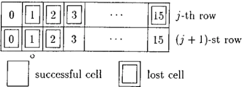
field [16], [21]. Then, by transmitting all the parity cells over the same VC as the information-bearing ones, the destination can determine the locations of lost cells in the coding matrix by detecting the gaps in the modulo-16 SN sequence. However, the consecutive loss of more than 15 cells, since it cannot be detected in this manner, is a potential source of decoding errors. Here, we describe a method which makes use of the correlation that already exists in the cell stream due to
Chapter 2. Two-Level FEC for ATM 19
0
□
0
0
0
0
successful cell 15 15 7 -th row {j + 1 )-st row' lost cellFigure 2.2: Consecutive loss of 18 cells.
coding to detect and mitigate the effects of such ill-conditioned losses.
Suppose that, for example, n — 16 and 18 cells are lost consecutively as shown in Figure 2.2. Then, the row decoder will misinterpret the received SN sequence, and regard the successful cells 0 of the j-th row and 3 , 4 , . . . , 15 of the
(j + l)-st row as belonging to a single row the second and third cells of which are
lost. Consequently, it will attempt to recover them li h > 2 . These are obviously unintended recoveries. Since each valid row has to be a consistent block according to the row coding rules, such unsuccessful attempted recoveries can be detected in certain cases as discussed below.
Let / be the number of lost cells detected in a row. Then li I > h, lost cell recovery is not possible, and the destination contents with the successful cells it has already received. Otherwise, all the lost cells can be recovered. In particular if
I < h, any set o( h — l successful cells can be regarded as being lost, and recovered
together with the I actually lost ones by using the remaining k successful cells. Then, a comparison of these recovered cells w’ith the respective successful ones indicates whether the row is valid or not. If they all match, the row and the recoveries are validated. A mismatch, on the other hand, indicates that the row is not a valid one, emd the recoveries of / actually lost cells are discarded. The
probability of a coincidental match in this comparison is where i is the
number of bits in the payload of a cell. Since i is 352 in the worst case'^, this probability is negligible even when I = h — 1. Therefore, row validation can be
^The payload lengths are 47, 45, and 44 octets respectively for the AAL type 1, 2, and 3/4 protocols [16], [21].
clone safely by regarding only one of the successful cells as being lost.
Now observe that, when n > 16, the decoding error due to the consecutive loss of more than 15 cells propagates since the subseciuent rows will similarly be misinterpreted. In other words, row-level synchronization between the encoder and the decoder will be lost. The validation procedure described above can also avoid decoding error propagation. When n > 16 is desired, it is reasonable in this regard to choose 7i as an integer multiple of 16. With this choice, each row is known to start and end with the same SNs, 0 and 15 without lo.ss of generality, and it is easier for the decoder to maintain row-level synchronization with the encoder. That is, in the case of detecting an invalid row, the procedure can be repeated successively each time shifting the potential row by 16 on the cell stream until a subsequent valid row is reached.
Finally note that the complete loss of one or more rows in a coding matrix disrupts proper operation of the column decoder similarly. The same procedure can also be performed over columns to validate the whole coding matrix, and hence, to achieve matrix-level synchronization between the encoder and the decoder.
2.2.2
Two-Level FEC for a V P Connection
Because the major purpose of using SNs is to enable in-sequence delivery of cells to the end user, no SNs are provided for cells belonging to a VP connection, which is used internal to the network. Therefore, a mechanism has to be devised to identify the lost cells in a coding matrix when two-level FEC is used for a VP connection. Ohta and Kitami have previously proposed transmission of auxiliary
Cell Loss Detection cells (CLD-cells) to be used for this purpose in the case of
coding over columns only. Here, we adopt this idea to the case of two-level coding, and briefly describe the mechanism in the following. For a more detailed description of the original mechanism, we refer the reader to [15].
The mechanism is illustrated in Figure 2..3. The encoding operation is per formed in the same manner as described at the beginning of Section 2. The only
Chapter 2. Two-Level FEC for ATM
21
time j i-cells CLD j i-cells CLD j i-cells CLD j i-cellsCLD
j p'-cells j p'-cells CLD' CLD' 2 + 1 j i-cells CLD j i-cells CLD j i-cells CLD j i-cells CLD j p'-cells CLD' j p'-cells CLD' p-cells p-cells p-cells p-cells p"-cells p"-cells 2+
1 k r = r j + r --- n -f r k'j p'-cells CLD' j p'-cells CLD' p"-cells
F igu re 2.3; Cell loss detection mechanism for the case of two-level F"EC for VP.
difference is that one CLD-cell is transmitted after every group of j i-cells. In the information field of each CLD-cell, there are 22-bit Cell Recognition Patterns (CRPs) copied from the preceding j i-cells. A CRP consists of the 16-bit VCI of the header and the first 6 bits of the information field of the corresponding i-cell. The VCIs remain unchanged as cells travel along the VP, and the first 6 bits of the information field include the T bit VC-SN [16], [21]. Therefore, the loss pattern in a block of j i-cells can be uniquely determined at the VP terminating node via a CRP matching procedure, as described in [15], provided that j is chosen properly and the corresponding CLD-cell itself is not lost.
cannot be determined uniquely, and lost cell recovery within that row is usually not possible. Therefore, the CLD-cells are excluded from row coding, and the h p-cells at the end of each row are generated by using the preceding r j i-cells only.
By transmitting all the parity cells (p-, p'-, and p"-cells) over a dedicated VC, lost parity cells can be identified based on the 4-bit VC-SNs. Therefore, they need not be appended CLD-cells. The CLD'-cells are parity cells generated according to the column coding rules by using the CLD-cells in the corresponding column. This provides a protection against loss of CLD-cells. One octet of the information fields of the CLD- and CLD'-cells is used for an 8-bit SN. Then, by transmitting all the CLD- and CLD'-cells over a dedicated VC, lost CLD- and CLD'-cells can be identified based on these 8-bit CLD-SNs.
Simitar to the case for information-bearing rows (first k' rows), the CLD'- cells are excluded from coding within parity rows (last h' rows). Then, the p"- cells are consistent parity cells according to both row and column coding rules. Consequently, having received or recovered all the CLD-cells, the decoder can identify all the lost cells in the coding matrix, and recover up to h losses per row and h' losses per column as desired.
Observe that this mechanism introduces a CLD- and CLD'-cell overhead in addition to the original parity cell overhead. Obviously, the larger the number j is, the more efficient the mechanism will be. As one octet of the information field of a CLD-cell is an 8-bit CLD-SN, the number of 22-bit CRPs that can fit in the remaining 47 octets is 17. However, a smaller value of j is required for proper operation of the mechanism. Ohta and Kitami showed that j has to be at most 1.5 so that the CRP matching procedure does not fail even in the worst case that all the i-cells in a row belong to the same VC and more than 15 cells, including a CLD-cell, are lost consecutively [1-5].
Chapter 3
Analytical Framework
In this chapter, we describe a discrete-time analytical framework to evaluate the performance of two-level FEC for a particular VC connection. The tagged traffic belonging to this connection is assumed to traverse a single node at which it interferes with N — I independent untagged traffic streams. We assume that there is an N x M ATM switch with dedicated output queueing at the node. Concentrating on the tagged output port, the node is modeled by an A^-to-1 ATM multiplexer with a FIFO output buffer of capacity B cells, as shown in Figure 3.1.
Our main objective here is to quantify the Cell Loss Rate (CLR) accurately for both constrained and optimal decoders. This requires the development of a tagged cell loss process model into which the traffic burstiness information is incorporated. In the following, after describing the input traffic model in Section 3.1, we introduce two such models. The first model is straightforward and exact, but has very high complexity. We discuss this model and its use in the analysis for the constrained decoder in Section 3.2. Since the exact model cannot be used when the columns of the coding matrix are decoded independently, we develop a simpler model which has much less complexity, and discuss its use for the case of optimal decoding in Section 3.3. In all these analyses, we assume that the end-to-end system recovers from losing more than 15 cells consecutively.
?i,oi = -7 = 1 - 0 !
9i,n =
F igu re 3.2; MC model of an individual source.
3.1
Input Traffic Model
We consider N discrete-time Markovian cell sources, one tagged and· — 1
independent untagged sources, at the input of the multiplexer. The MC model of one source is shown in Figure -3.2, where the states 0 and 1 correspond respectively to the “idle” and “active” states of the source. The state transitions occur once per .s/oi, which is the unit time required to transmit a cell over the output link. A source generates one cell per slot when active, and no cell at all when idle. Then, the stationary probability of the active state, given by
i>i = (1 - o )/(2 - a - f i ) , (3.1)
is the normalized load offered by one source, where a and /5 are respectively the idle-to-idle and active-to-active state transition probabilities as shown in Figure 3.2.
Chapter 3. Analytical Framework 25
in Section 2.1, destroys the Markovian behavior of the tagged source. However, we assume that it is preserved even after encoding, and reflect the effect of parity overhead in the traffic parameter ¡3 only so that the tagged load is increased by the factor 1//?, where R is the code rate kk'f nn'. That is, we modify ¡3 as
= (1 - R){2 - a ) + R!3 so that the normalized effective tagged load becomes
Pei = (1 - a )/(2 - a - 3C) = pt!R,
(3.2)
(3.3) where pt is the normalized tagged load before encoding. The assumption that the traffic parameter o; remains the same as before parity cell insertion is reasonable due to the memoryless property of the geometric idle duration distribution [12].
VVe assume that — 1 untagged sources are independent and identical. The
aggregate untagged source can then be modeled by an A^-state MC with the state variable being the number of active untagged sources, or equivalently, the number of simultaneous untagged cells generated in a slot. The state transition probabilities for this MC follow from those for the individual source MC. The subscript 1 in of Figure 3.2 is attributed to the single source. With similar notation, let h j = 0 ,1 ,2 ,. .., A" — 1, be the state transition probabilities
for this MC. Observe that a transition from, state i to state j occurs when / of i active sources become idle, and j — (i — 1) oi N — I — i idle sources become active simultaneously in a slot. Then, we have
= É ( i ) ‘ .‘ 'l j - i + I
(3.4)
where / = max(0,f - j ) and 7 = min(f. A ''- 1 - j ) . It can be shown that (3.4) gives the transition probabilities of Figure 3.2 when N = 2, i.e., when there is only one untagged source.
The individual cell source described above is much simpler than the inter rupted or Markov modulated Bernoulli sources, which are used widely in the literature, e.g., in [23] and [24]. Yet, this simple source is capable of generating