______________________________ MINERAL MINING ________________________________
_______________________________________________________________________________________________________________________ ________________________________________________________________________________________________________________________________
TECHNOLOGY
Prediction of Top Coal Cavability Character
of a Deep Coal Mine by Empirical and Numerical Methods
İ. F. ÖgeMuğla Sıtkı Koçman University, Muğla, Turkey *e-mail: [email protected]; [email protected]
Received March 23, 2018 Revised July 20, 2018 Accepted October 10, 2018
Abstract—Longwall top coal caving mining provides high productivity where thick coal seams exist. The
study aims to predict the cavability character of the top coal for deep and thick coal seam in Soma lignite basin located at Western Turkey. Active longwall top coal caving mines are at a depth of 100–400 m and they were used for comparison purposes. New coal mining operations will be initiated in deep sectors of the basin in the future. Future longwall top coal caving operations will be unique under a depth of 700–1200 m with a varied thickness. Several empirical and numerical methods are utilized in the study. Pre-existing empirical approaches lack of essential data and additional numerical modeling is necessary to be employed in order to assess cavability character of the projected new mines. Numerical modeling provides a practical platform for construction of ground response curves. Existing mines and future mining operations can be evaluated and compared by ground reaction curves and a final conclusion about cavability character is reached.
Keywords: Longwall mining, longwall top coal caving (LTCC), finite element analysis, ground response curves, cavability index.
DOI: 10.1134/S1062739118054903
INTRODUCTION
Conventional longwall coal mining is restricted to a seam thickness thinner than 5 m. Although there are varied thick coal seam extraction methods such as multi slice longwall method, longwall top coal caving (LTCC) method has the highest popularity due to requiring low development work per produced coal. In the past, top coal caving operations were conducted in several regions over the world. Currently, China meets approximately the half of worldwide coal production; nearly half of it is supplied from thick coal seams [1, 2]. Turkish top coal caving experience lies back to early 80s and new thick coal mines are being proposed and initiating production [3–5].
Top coal caving can simply be explained as gaining the coal overlying the shield (top coal) at rear canopy flipper of the longwall shield. Longwall advance is conducted by typical face cutting. Stress distribution like face abutment pressure and stress drop at shield plays important role for yielding and crushing the top coal which provides flowing character to the coal through the rear canopy flippers. LTCC requires elaborateness in face operations which can lead to success otherwise problems will be expected. The method provides increased productivity, less development length per produced coal tonnage. When LTCC is compared to other thick coal seam production methods like multi-slice longwall method, it is superior from technical and economical point of view [6–8]. A multiple slice longwall top coal caving mining for a seam thickness greater than 30 m is presented in Fig. 1. The method can also be applied by a single pass LTCC for seam thickness up to 12–15 m.
Fig. 1. Multiple slice longwall with top coal caving [9].
In coal seams having greater thickness, multi-pass LTCC can be applied in order to achieve better recovery [5, 9, 10]. Still, questions on cavability tendency of the top coal remain hard to be answered accurately. Findings from a top coal cavability assessment may help deciding on production fashion being either multi slice or single pass LTCC for a Greenfield project as being a challenging rock mechanics problem. One of the other challenging part of the problem is the assessment will be conducted for a proposed operation of LTCC under great depth since worldwide top coal caving experiences are generally restricted up to 600 m and deeper top coal caving experiences are rare over the world and absent in Turkey.
1. SOMA LIGNITE COAL BASIN
Soma lignite coal basin is located at Soma province in Manisa (Turkey). An open cast mine is under operation in the northern region of the basin where the coal seam lies at shallow depth. In neighbourhood, underground coal mines are being operated at the depth range of 150–400 m. Soma Eynez coal mine has initiated production last year at similar depths. New underground coal mines are being projected having greater mining depth of 700–1200 m which are owned by government and private companies at an approximate distance of 5 km far from the mines under operation.
Although there are multiple coal seams, main coal seam named as KM2 has the economic
importance and being produced in the basin (Fig. 2). Thickness of KM2 varies between 5–30 m along
the basin. Quality and calorific value of the coal decreases from top to bottom. Around mid-level of the coal seam, clay-claystone content increases and strength of coal and structural quality decreases accordingly. Miocene aged KM2 underlain by M1 geological unit consisting of poorly cemented
clayey conglomerate and sandstones. M1 unit can be encountered having higher clay content in
several regions of the basin which causes operational problems. Miocene M2 unit consists of marl and
overlies KM2 horizon with a thickness of 30–70 m. In the northern region of the basin coal seam
inclination is up to 25° and it drops to nearly horizontal at southern and south-western regions excluding tectonically affected regions. M2 unit is present in massive structure with widely spaced
beddings and sub-vertical calcite filled joints. A three-meter-thick zone (considered as immediate roof) of M2 overlies the KM2 coal, is structurally more deformed when it is compared to the upper
zones of M2. Overburden lying on M2 unit is relatively weaker than M2 unit. Upper zones of
overburden mostly consist of Pliocene aged claystone, marl, sandstone, pebblestone, limestone intercalations. Thickness and presence of the units vary along the basin. One of the main character is tectonic disturbance is strong over the basin and drastic changes on the structural quality of the rock mass can be frequently observed in short intervals.
Fig. 2. Generalized stratigraphy of Soma coal basin [9].
Rock mass classification values, Q-system [11, 12], the rock mass rating (RMR) method [13, 14], Geological Strength Index (GSI) [15, 16] values and intact uniaxial compressive strength σc are listed in Table 1.
Input parameter determination work was handled as a separate work by the author based on laboratory tests and borehole investigations conducted for basin where the coal depth is greater than 800 m, and final findings are reported in this research. The parameters to be used in the analyses are given in Table 2.
Table 1. Estimated rock mass classification ratings
Content Rock type Thickness, m Basic-RMR Q-System Geological strength
index GSI σc, MPa
Roof Marl ~ 30 50–65 1.00–10.0 60–80 50–100 Immediate roof Marl ~ 3 35–55 0.02–0.2 40–60 50–100 Coal Lignite ~ 16 20–45 0.01–0.2 30–55 5–30 Floor Conglomerate — 35–55 0.02–1.0 50–60 1–30 Overburden Limestone, siltstone, claystone ~ 800–1200 15–50 0.01–1.0 15–45 1–80
stop~4sfar>;u°'v;tia,,
.Ball . SitkiffciUmAmtm A ~~bmltie ~'~are,
~lered
marl:
Upper lignito seim
tow~~igni~•mr
.()nafnlifimeiea'.m) · ~ ~~lized.J~.
R
I.Mm
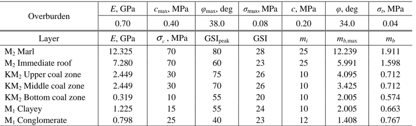
Table 2. Rock mechanics parameters of the geological units
Overburden E, GPa cmax, MPa φmax, deg σtmax, MPa c, MPa φ, deg σt, MPa 0.70 0.40 38.0 0.08 0.20 34.0 0.04 Layer E, GPa σc, MPa GSIpeak GSI mi mb,max mb
M2 Marl 12.325 70 80 28 25 12.239 1.911 M2 Immediate roof 7.280 70 60 23 25 5.991 1.598
KM2 Upper coal zone 2.449 30 75 26 10 4.095 0.712 KM2 Middle coal zone 2.449 30 70 26 10 3.425 0.712 KM2 Bottom coal zone 0.319 10 55 20 10 2.005 0.574
M1 Clayey 1.225 15 55 24 10 2.005 0.663 M1 Conglomerate 0.798 25 40 23 12 1.408 0.767
E stands for the rock mass elastic modulus; cmax, φmax, σtmax are peak values for cohesion, internal friction angle and tensile
strength, respectively; c, φ, σt are residual values for cohesion, internal friction angle and tensile strength, respectively.
In Soma coal basin, several researchers have estimated rock mass properties for various problems [5, 17, 18] and when the input parameters for the analyses are compared to those studies, findings in this study are relatively higher. The researchers dealt with gate road [5], pillar recovery, pillar stability and shaft-production interaction [18, 19] problems. That is why the parameters are relatively higher in this study since this research is related to top coal cavability and parameters are chosen conservatively high. Residual state strength parameters were calculated by assigning rock mass a GSI value for residual state [20] and Hoek–Brown parameters were calculated as described in [21].
2. LONGWALL TOP COAL CAVING METHOD IN SOMA BASIN
Semi-mechanized and mechanized longwall faces are present in northern Soma basin [5, 18, 22]. In northern Soma coal basin, Isiklar colliery is being operated in 20–25° steep coal seam with horizontal longwall faces, retreating parallel to the strike of the coal at 150–300 m depth. Establishing horizontal longwall faces in 20–22 m thick coal seam, restrains the face length to 60 m. Top coal thickness is adjusted to be in the range of 16–18 m. Due to short face length, competent main roof (M2 Marl) and shallow depth, poor recovery of top coal and standing of main roof were encountered
especially for the upper production panels. Production sequence starts at the uppermost panel and finishes at the lowermost panel. Especially after production of second and third panels, complete caving and drawing (recovery >90%) of the top coal was achieved by the help of pre-fracturing blasting and progressive damage of main roof. Preferred shield face supports in that section, have single armored face conveyor and top coal are mostly drawn through from large front canopy flipper which is an advantage against blockages by large coal or rock blocks. Main roof caving tendency increased and became no longer a problem for further production due to previous production induced damage to the roof.
Other coal mines neighbouring to the shallow ones, operating in horizontal thick coal seams (up to 30 m) preferred production of upper most coal slice in conventional longwall method which is expected to cave the main roof during top slice production. The rest of the coal seam can be produced in one or two slices of semi-mechanised and mechanized LTCC [5, 9, 10, 19] with varied face lengths. Face lengths are 180–200 m and depth varies between 200 and 400 m in Eynez sector, with discrete slicing: mining of the upper slices conventionally and after that second slice mining in the form of LTCC as described in [5]. The longwalls are being operated by the way that maximizes top coal recovery (>90%) which is achieved by allowing acceptable dilution.
Southern Soma coal mines are under projecting and development stage. At 700–1200 m depth, longwall face lengths are supposed to be at least 160 m and restricted by faults and other geological structures. Coal seam inclinations vary within the limit of 6–10°. Under great depth and extended longwall face lengths, cavability character is expected to be improved and conditions can lead to single pass LTCC production of a 16 m thick coal seam which is beyond the common limits considering high recovery.
3. CAVABILITY ASSESSMENT OF DEEP COAL SEAM
Assessing cavability character of top coal can be dealt with several approaches namely; numerical analysis and empirical methods which are mentioned in [6, 23]. Still, there are few studies on the issue. Empirical approaches lack of detailed input data about operational factors which have direct effect on the success of caving. They can be listed as: necessity and application of pre-fracturing of top coal by blasting or hydraulic fracturing, longwall face length, support density, face advance rate, shield alignment, top coal drawing duration-sequence, set pressure of shields. Adaptation of those data to empirical approaches is not practically possible. However, the most straight forward geological and rock mechanics parameters are obvious and they are included in the following cavability index approaches. These parameters include: Chinese y-index, uniaxial compressive strength of coal, coal fracture index, stone band thickness and top coal thickness. CI index proposed by the Commonwealth Scientific and Industrial Research Organization (CSIRO, Australia) utilizes mining depth, test scale strength of coal and top coal thickness. Both index values can be utilized in order to estimate total coal recovery. In [24] it is noted that the abovementioned studies are based on Chinese mining cases. It should be noted that sample size in several empirical approaches are limited and does not cover great depths thus, they are not used in the study.
Another cavability index work proposed by [6] is based on numerical modelling findings which were carried out by a series of Discrete Element codes. The parameters affecting cavability were found to be: deformation modulus, in-situ stress at all axes, seam thickness, spacing of vertical and horizontal jointing. Numerical modelling work was verified by several actual mining cases.
In [25] they studied the effect of coal seam inclination on cavability character and stated that steeper the seam decreases tendency of top coal to cave presenting a quantification and classification based on numerical modelling.
Many researchers prefer using commercially available Distinct Element Codes namely Itasca PFC, UDEC and 3DEC codes which are capable of handling discontinuum analysis [6, 8, 25–27] for top coal caving simulation or problems in top coal caving mines. The Itasca codes or discontinuum analysis methods are well suited for simulating caving process for a rock mass having geological structures like coal (cleats, bedding planes and jointing). Another advantage of the codes is the ability to compute large deformation. The codes require input parameters namely discontinuity spacing, orientation, rock block geometry, discontinuity deformability and strength in addition to intact rock parameters. However, most of the researchers handle the problem by assuming top coal flows as a granular medium which is not true for all instances. Continuum approaches like finite element method, finite difference method are also preferred [2, 5, 8–10, 23, 28] in the analyses of the problems involving top coal caving.
Abutment pressure acting on the face plays an important role in fracturing of the top coal [8, 23]. Intact coal and roof failure and material fracturing is another essential issue in addition to structurally controlled failures mostly simulated by discontinuum analysis. By increasing depth and in-situ stress increase, discontinuities became tightly interlocked due to increased normal stress. Increased stress levels induce material failure and impact of structurally controlled failure is expected to be going down when it is compared to a shallow mine bears to competent intact rock material which increases the applicability of continuum numerical approaches.
In Southern Soma coal basin overburden thickness is greater than 700 m. Roof is competent with widely spaced joints and beddings. In that study utilization of numerical modelling aims to observe rock material failure in the process and investigation of top coal cavability character by utilizing and comparing ground reaction (convergence-confinement) curves for longwall face and failure extents. Still, foreseeing the size and shape of broken top coal is challenging and difficult to estimate, being valid for all analysis types.
4. EMPIRICAL APPROACH
Since a real mine cases exist at several depths from 150 to 400 m, they were taken into account for comparison purposes. Active LTCC longwall faces and top coal caving performance was observed by means of recovery. Soma coal mines located at northern sectors at relatively shallower depth, employment of pre-fracturing blasting is necessary, then sufficient caving is obtained with slow longwall advance rates. Due to small license areas of the mines, operators aim to produce at very high recovery (>95%) and prefer to draw additional roof rock with coal when it is compared to typical LTCC applications. Underground mining induced conditions of Isiklar Colliery producing steep and thick coal seam are also missing in empirical approaches. Due to the absence of in-situ stress measurements, field stress was imposed according to gravity and assuming horizontal to vertical stress ratio equals to unity for deep production levels. Input parameters for the approach are vertical
v
σ and horizontal σh virgin stress, uniaxial compressive strength σc, top coal thickness T, modulus of elasticity of coal Ei, vertical J and horizontal v J joint spacing values. In [6] the authors describe h
main caving distance MCD as the distance of face at a point where all top coal caves to the mined void from initial position. In cavability index, caving of the roof is not taken into account and no data input is required for the work. Top coal recovery TCR is the percentage of coal recovered. 800, 400, 300 and 150 m deep mining cases are taken into account with upper and lower bound of strength of the rock mass. In addition to top coal recovery and main caving distance, modulus of elasticity of intact coal can also be found by equations given below [6]:
0.0316 0.1514 2 0.161 1.7705, MCD 2.451 0.46 12.56 19.56 22.417 23.84, TCR 63.13 8.85 82.447 0.015 0.0000401 91.093. h i c i h v i v v v E E T J J e T E J σ σ σ σ − − = + = + + + + − = − − + + +
In Table 3 three different depths from [6] are considered. Jointing, deformability values are chosen considering weak and strong sections of the coal seam. Top coal thickness of 13 m is taken constant for all analyses in order to be consistent.
Table 3. Cavability assessment according to cavability index by [6]
Parameter
Depth of coal seam (m) and cavability degree 800 Weak 800 Strong 400 Weak 400 Strong 150 Weak 150 Strong T, m 13.0 13.0 13.0 13.0 13.0 13.0 v σ , σh, MPa 18.3 18.3 8.8 8.8 3.3 3.3 i E , GPa 4.2 6.6 4.2 6.6 4.2 6.6 h J , J , m v 0.1 0.2 0.1 0.2 0.1 0.2 MCD 8.2 17.3 12.6 21.7 15.8 24.9 TCR 93.5 64.0 89.7 60.2 88.7 59.2
When stronger coal seam is considered, top coal recovery is around 60% for all depths. Main caving distance MCD of top coal increases by increasing depth. Stronger coal seam samples fall into Class III and IV which are fair and poor cavability conditions. Current practice of Soma mines includes pre-fracturing blasting, slow advance rates of longwall especially at around 150 m depth. These practices enable production of stronger sections of top coal. According to the results in Tab. 3, even at 800 m depth it is understood that additional measures like pre-fracturing [29] can still be necessary since top coal recovery increases by only 5%. It is observed that the depth has less influence while mechanical properties of coal plays a stronger role. The empirical method does not consider face length, roof behavior or details which make a numerical analysis use necessary.
5. CONSTRUCTION OF GROUND RESPONSE CURVES BY NUMERICAL MODELLING
Rocscience Phase2 v.8 plane strain finite element analysis program was used in numerical modelling work for this study [30]. The aim is the problem in the research can be handled by a practical approach. Ground response (Convergence-confinement) curves [31, 32] were utilized in order to compare the top coal caving character which is a beneficial tool when a plane-strain model is in use. Ground response curves are used in tunnelling support design however, there are several researchers who used the method in longwall rock-support interaction analyses [33, 34], but not for top coal cavability investigation. In modeling work, main and tail gates were excluded and only the longwall faces were modeled. Finite element mesh density was increased gradually around the longwall faces, at the area of interest. Elastic-brittle-plastic behaviour was accepted in the analyses, for overburden Mohr–Coulomb, for roof, coal and floor failure criterions were imposed to the model as shown in Table 2.
The cross-section is constructed parallel to the face. It was used for examination of required longwall face length ensuring successful top coal caving and main roof and construction of ground response curves. Observing tensile yielded element extent at the roof in vertical axis, displacement magnitudes reflect important data on cavability performance.
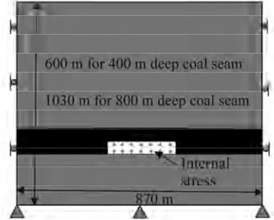
Main principle of the ground reaction model is based on modeling the longwall face and gradually reduction of internal stress which is applied to the boundaries of the longwall opening. General dimensions and boundary conditions for the ground reaction calculation models are illustrated in Fig. 3.
After initialization of the in-situ stress at the beginning stage of the model, internal stress reduction was applied (Tab. 4). Then it is possible to construct ground reaction curves by obtaining displacements to the corresponding internal stress.
Table 4. Internal stress reduction factors σv for two depths (400 and 800 m)
Modeling stage σv
Internal stress, MPa 400 m 800 m 1 1.0 9.0 18.9 2 0.8 7.2 15.1 3 0.6 5.4 11.4 4 0.4 3.6 7.6 5 0.2 1.8 3.7 6 0.1 0.9 1.9 7 0.075 0.7 1.4 8 0.050 0.5 0.9 9 0.025 0.2 0.3 10 0.0 0.0 0.0
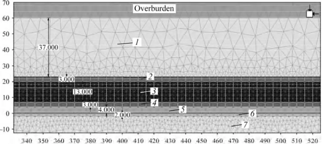
In modeling of 400 and 800 m deep coal seams with equal geological thickness, only overburden material thickness was altered. In Fig. 4 a detailed presentation of the coal seam is given. The longwall face is established at the zone labeled by intermediate coal zone with a face height of 3 m.
Ground response behavior was investigated by considering 3 different longwall face lengths (60, 160 and 200 m) at two different depths (400 and 800 m). Additionally, Isiklar Colliery with a steep coal seam was modeled (Fig. 5) and ground response behavior of first three panels were analyzed by construction of a different model due to significant difference to the deep and near-horizontal coal seams in 400 and 800 m deep cases. In Isiklar Colliery longwall face lengths are fixed to 60 m due to horizontal longwalls in strike direction of the coal seam.
Common support densities for longwall face supports are generally around 1 MPa or lower. In fact, those support pressures cannot be compared to stress carried by face itself. Vertical stress at face is accepted to be 2–4 MPa which is close to the average residual strength of coal mass. Obviously the major supporting element is the face itself. Longwall support carries dead rock load, improves bedding interlocking and reducing bedding separation then it ensures stability for the face environment. However, if the roof will converge, it is not resistible by typical shield support pressures and then it will finally converge.
Fig. 4. Numerical model of southern Soma coal strata: 1—roof М2; 2—immediate roof М2; 3—upper coal zone КМ2; 4—intermediate coal zone КМ2; 5—bottom coal zone КМ2; 6—clayey conglomerate М1; 7—conglomerate, greywacke, schist М1. 70 r - - - ---,.==a;a=;=..--- - - - ; - --, Overburden 60 50 40 30 20 10 - 1 0 + - - -;::~::;-,:;-_-:;,~,--....:...:..:..:.,=;,;,;<N'i'- - - - ; . . _l.;,;.J'---::,-' -JO '---.---,---,--.----.--.----.----,---,---,--.----.--.----.----,---,---,--.----.--' 3-10 3-0 :.60 110 "!IO J90 ,100 10 420 430 440 4:10 1,0 ,no 4 o 490 -oo ·10 520
Fig. 5. Finite element mesh generated for steep coal seam mining with horizontal longwall panels.
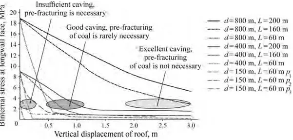
Depth and face length of the longwall faces are identified and corresponding ground reaction curves (Fig. 6). When we examine the problem by comparing face lengths, 60 m long faces obviously seem to have low deformation potential. For same internal stress on longwall face boundary, deformation attained is considerably small. Same conclusion can be suggested by considering the slopes of the curves range (2–4 MPa) which can be identified as strata stiffness. In Soma coal basin there are many longwalls operating with 60–80 m long faces. Caving of the roof as well as top coal caving is a common problem especially for the first panel of a sector. Current mine operators mostly suggests caving of the roof first by operating a conventional longwall along the upper most slice of the seam if the depth is smaller than 300 m. When mine induced deformation and stress have great impact on a particular area, then even in longwalls with short face, roof or top coal are caved more easily. Ground reaction curves suggest for 16 m thick coal seam, a single pass LTCC operation with 60 m long face length, will not have sufficient top coal caving. 160 to 200 m long longwall faces are expected to have similar and good caving tendency at 400 and 800 m depth. 150 m deep mining case belongs to Isiklar Colliery, 400 m deep mining case belongs to Eynez colliery and 800 m deep case reflects future deep mining case conditions.
An important precaution is ground reaction curves which are constructed by following the concepts presented in this research cannot be used for estimation of support requirements.
Fig. 6. Ground response curves of longwalls at Soma Coal Basin at different depth and face length.
500 400 300 200 100 0 -100
Overburden Abandoned open
Waste dump -}()0 -200 -100 0 100 200 300 400 500 600 700 800 900 1000 1100 1200 1300 )400 1500 <'l 0.. 20 ~ QJ u ~ 16 C'l 14 :; G} 12 C: .9 10 iii ~ 8 ~ I) iii
Insufficient caving. pre-fracturing is necessary
Good caving, pr~fracturing of coal is rarely nece sary
Excellent caving,
pre-fracturi og of coal is not nt:ct.:ssary 0.5 1,0 1.5 2,0 2.5 ~ O Vertical displacement of roof, m - rf: 800 m, l =200 111 - £1=800 m, L= 160 Ill ... d=800 m. l =GO m - d=400 m. l =200 111 - d-=-400 m,L= 160 01 d=40U m. L=6U rn - c/=l50m.l =6Ump 1 - - d= 150 m • l =60 mp 2 d=l50 m, l=•O mp 1
CONCLUSIONS
Every rock engineering problem suffers from uncertainty to a degree due to geological conditions and operational and construction factors. In Soma Lignite Basin, longwall top coal caving mining activities take place at 150–400 m depth. The mining conditions and parameters are known. For the benefit of future mining operations, caving performance of deep coal seam was investigated in the study. Previously developed caving index was used but additional analyses were required. This research showed ground response curves can be utilized in order to assess the cavability character of the top coal. Supporting the curves by existing mine conditions enabled the research to give a conclusion about cavability as no precautions will be necessary for pre-fracturing of the top coal. Still, important operational parameters cannot be involved in the analyses, like: longwall face advance rate, set pressures, capacities of the shields, precise alignment of the face. Success of a top coal caving longwall operation is strongly dependent on the operation fashion and methodology as well as the compatibility and conformity of the mechanization to the mine.
ACKNOWLEDGMENTS
The author thanks Polyak Eynez Energy Mining A.Ş. and Fina Energy and its personnel for supporting the scientific research and providing necessary data for the study. The author personally thanks Geological Engineers of Polyak Eynez, Feridun Emre Yağımlı, Ali Türkoğlu, Mehmet Kılıç for providing extensive data on the geology of the area and Ahmet Erel who shared his extensive mining experience in Soma Basin.
REFERENCES
1. Wang, J., Yang, S., Li, Y., Wei, L., and Liu, H., Caving Mechanisms of Loose Top-Coal in Longwall Top-Coal Caving Mining Method, Int. J. Rock. Mech. Min. Sci., 2014, vol. 71, pp. 160–170.
2. Yasitli, N.E. and Unver, B., 3D Numerical Modeling of Longwall Mining with Top-Coal Caving, Int.
J. Rock. Mech. Min. Sci., 2005, vol. 42, no. 2, pp. 219–235.
3. Doktan, M. and İnci, Y., Status of Thick Seam Coal Mining over the World and in Turkey, Proc. 10th
Turkey Scientific and Technical Congress, Ankara, 1987, pp. 51–65.
4. Doktan, M. and İnci, Y., The Production Method Adapted in Underground Pits of ELI-Soma Region and Possibilities of Mechanisation, Madencilik, 1986, vol. 25, pp. 5–20.
5. Basarir, H., Oge, I.F., and Aydin, O., Prediction of the Stresses Around Main and Tail Gates During Top Coal Caving by 3D Numerical Analysis, Int. J. Rock. Mech. Min. Sci., 2015, vol. 76, pp. 88–97.
6. Vakil, A. and Hebblewhite, B.K., A New Cavability Assessment Criterion for Longwall Top Coal Caving,
Int. J. Rock. Mech. Min. Sci., 2010, vol. 47, no. 8, pp. 1317–1329.
7. Suchowerska, A., Merifield, R., and Carter, J., Vertical Stress Changes in Multi-Seam Mining Under Supercritical Longwall Panels, Int. J. Rock. Mech. Min. Sci., 2013, vol. 61, pp. 306–320.
8. Alehossein, H. and Poulsen, B.A., Stress Analysis of Longwall Top Coal Caving, Int. J. Rock. Mech. Min.
Sci., 2010, vol. 47, no. 1, pp. 30–41.
9. Aksoy, C.O., Küçük, K., and Uyar, G.G., Long-Term Time-Dependent Consolidation Analysis by Numerical Modelling to Determine Subsidence Effect Area Induced by Longwall Top Coal Caving Method, Int. J. Oil Gas Coal Tech., 2016, vol. 12, no. 1, pp. 18–37.
10. Aksoy, C.O., Küçük, K., and Uyar, G.G., Safety Pillar Design for Main Galleries in Multi-Slice Longwall Top Coal Caving Method, Int. J. Oil Gas Coal Tech., 2015, vol. 9, no. 3, pp. 329–347.
11. Barton, N., Lien, R., and Lunde, J., Engineering Classification of Rock Masses for the Design of Tunnel Support, Rock Mech., 1974, vol. 6, no. 4, pp. 189–236.
12. Norvegian Geotechnical Institute, Using the Q-System Rock Mass Classification and Support Design. http://www.ngi.no. Cited December 15, 2017.
14. Lowson, A.R. and Bieniawski, Z.T., Critical Assessment of RMR-Based Tunnel Design Practices: a Practical Engineer’s Approach, Proc. Rapid Excavation and Tunneling Conference, Washington, DC, 2013, pp. 180–198.
15. Hoek, E., Carter, T.G., and Diederichs, M.S., Quantification of the Geological Strength Index Chart, Proc.
47th U. S. Rock Mechanics/Geomechanics Symposium, California, 2013, ARMA 13–672, pp. 1–8.
16. Marinos, V., Tunnel Behavior and Support Associated with the Weak Rock Masses of Flysch, J. Rock.
Mech. Geotech. Eng., 2014, vol. 6, no. 3, pp. 227–239.
17. Aksoy, C.O., Kose, H., Onargan, T., Koca, Y., and Heasley, K., Estimation of Limit Angle Using Laminated Displacement Discontinuity Analysis in the Soma Coal Field, Western Turkey, Int. J. Rock.
Mech. Min. Sci., 2004, vol. 41, no. 4, pp. 547–556.
18. Aksoy, C.O., Kose, H., Yalçin, E., and Heasley, K., Mark Enhancing the Safety of Remnant Pillar Recovery in Lignite by Numerical Modelling, CIM Bulletin, 2004, vol. 97, no. 1082.
19. Aksoy, C.O., Three-Dimensional Finite Element Analysis of an Undermined Shaft at the Hustas Mine, Turkey, CIM Bulletin, 2005, vol. 98, no. 1089, p. 38.
20. Cai, M., Kaiser, P.K., Tasaka, Y., and Minami, M., Determination of Residual Strength Parameters of Jointed Rock Masses Using the GSI System, Int. J. Rock. Mech. Min. Sci., 2007, vol. 44, no. 2, pp. 247–265. 21. Hoek, E., Carranza-Torres, C., and Corkum, B., Hoek-Brown Failure Criterion—2002 Edition, Proc.
NARMS-TAC Conference, Toronto, 2002, pp. 267–273.
22. Yılmaz, A.I., Büyükyıldız, G., Ekici, A., Çalık, M., Önder, Ö., and Aksoy, C.O., Staff Transportation Two Way on the Belt Conveyor, Acta Montanistica Slovaca, 2013, vol. 18–3, pp. 141–150.
23. Humphries, P. and Poulsen, B., Geological and Geotechnical Influences on the Caveability and Drawability of Top Coal in Longwalls, Proc. Coal 2008: Coal Operators' Conference, Aziz N. (Ed.), University of Wollongong and the Australasian Institute of Mining and Metallurgy, 2008, pp. 56–66.
24. Dattatreyulu, J.V., Khanal, M., Adhikary, D., and Balusu, R., Geotechnical Studies for Introducing High Capacity Longwalls and Longwall Top Coal Caving Mining in SCCL: A Case Study, Proc. 4th Coal
Summit, New Delhi, India, 2012.
25. Quang, H.D., Mitra, R., and Hebblewhite, B., Effect of Seam Dip on Face Orientation of Longwall Top Coal Caving, Proc. 43rd U. S. Rock Mechanics Symposium and 4th U.S.–Canada Rock Mechanics
Symposium, Asheville, North Carolina, 2009, ARMA-09-110, pp. 367–376.
26. Wang, J., Zhang, J., Song, Z., and Li, Z., Three-Dimensional Experimental Study of Loose Top-Coal Drawing Law for Longwall Top-Coal Caving Mining Technology, J. Rock Mech. Geotech. Eng., 2015, vol. 7, no. 3, pp. 318–326.
27. Su, H., Bai, J., Yan, S., Chen, Y., and Zhang, Z., Study on Gob-Side Entry Retaining in Fully-Mechanized Longwall with Top-Coal Caving and Its Application, Int. J. Min. Sci. Technol., 2015, vol. 25, no. 3, pp. 503–510. 28. Xie, H., Chen, Z., and Wang, J., Three-Dimensional Numerical Analysis of Deformation and Failure
During Top Coal Caving, Int. J. Rock. Mech. Min. Sci., 1999, vol. 36, no. 5, pp. 651–658.
29. Huang, B., Wang, Y., and Cao, Y., Cavability Control by Hydraulic Fracturing for Top Coal Caving in Hard Thick Coal Seams, Int. J Rock. Mech. Min. Sci., 2015, vol. 74, pp. 45–57.
30. Rocscience, Inc. Phase2, v. 8. Rocscience Inc., Toronto, Canada, 2012.
31. Brown, E.T., Bray, J.W., Ladanyi, B., and Hoek, E., Ground Response Curves for Rock Tunnels, J. Geotech.
Eng., 1983, vol. 109, pp. 15–39.
32. Carranza-Torres, C. and Fairhurst, C., Application of the Convergence-Confinement Method of Tunnel Design to Rock Masses that Satisfy the Hoek-Brown Failure Criterion, Tunn. Undergr. Space Technol., 2000, vol. 15, no. 2, pp. 187–213.
33. Barczak, T.M., A Retrospective Assessment of Longwall Roof Support with a Focus on Challenging Accepted Roof Support Concepts and Design Premises, Proc. 25th International Conference on Ground
Control in Mining, Morgantown, WV, 2006, pp. 232–244.
34. Medhurst, T.P. and Reed, K., Ground Response Curves for Longwall Support Assessment, Trans. Inst.
![Fig. 1. Multiple slice longwall with top coal caving [9].](https://thumb-eu.123doks.com/thumbv2/9libnet/3849373.35099/2.918.240.691.82.301/fig-multiple-slice-longwall-coal-caving.webp)
![Fig. 2. Generalized stratigraphy of Soma coal basin [9].](https://thumb-eu.123doks.com/thumbv2/9libnet/3849373.35099/3.918.238.693.84.688/fig-generalized-stratigraphy-soma-coal-basin.webp)
![Table 3. Cavability assessment according to cavability index by [6]](https://thumb-eu.123doks.com/thumbv2/9libnet/3849373.35099/6.918.133.801.880.1092/table-cavability-assessment-according-cavability-index.webp)