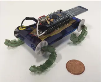
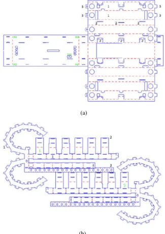
C-Quad: a miniature, foldable quadruped with C-shaped compliant legs
Tam metin
Şekil


Benzer Belgeler
The administration of VEGF at the beginning of reperfusion caused decreases in MDA levels and SOD activities and increases in GSH levels and CAT activities for kidney and
1 Ahi Evren G¨o˘g¨ us Kalp Damar Cerrahisi E˘gitim Ara ¸stırma Hastanesi, KVC klini˘gi, Trabzon, Turkey; 2 Ahi Evren G¨o˘g¨ us Kalp Damar Cerrahisi E˘gitim Ara ¸stırma
Gösteril m eye çalışıldığı üzre, reklam ın yaptığı değişiklik, m ollalık yerine “ağır abi”liği olum lam ak gibi bir sonuca varm ıştır ki bunun
To cite this article: Bilgi Gungor, Fuat Cem Yagci, Ihsan Gursel & Mayda Gursel (2014) Forging a potent vaccine adjuvant: CpG ODN/cationic peptide nanorings, OncoImmunology,
Değer yargıları- na, övgü ve sövgü ifadeleri olarak diğer sözlü ürünlere kıyasla daha doğrudan işaret eden ve kültürel kodların yeniden üretilmesi
“Proven reserves of oil– Generally taken to be those quantities that geological and engineering information indicates with reasonable certainty can be recovered in the
amac›, 2007 y›l› Samsun ‹li perinatal mortalite h›- z›, erken ve geç neonatal mortalite h›z›, bebek mortalite h›z› ve ölüm nedenlerini, Samsun ‹l
Three distinct effects of the SOC are expected in the EC as (i) a controllable mixture of the dark and bright condensates (DC and BC hereon) in the ground state, (ii) finite
