Slowing surface plasmon polaritons on plasmonic coupled cavities
by tuning grating grooves
Sinan Balci,1,a兲Askin Kocabas,2Coskun Kocabas,1and Atilla Aydinli1
1Department of Physics, Advanced Research Laboratories and Turk Telekom Laboratory, Bilkent University,
06800 Ankara, Turkey
2FAS Center for Systems Biology, Harvard University, Cambridge, Massachusetts 02138, USA 共Received 30 July 2010; accepted 3 September 2010; published online 28 September 2010兲 We investigate slow surface plasmon polaritons共SPPs兲 in plasmonic waveguiding bands formed by coupled plasmonic cavities on Moiré surfaces. We demonstrate controlling the group velocity and dispersion of the SPPs by varying the depth of the plasmonic Bragg grating groove. Changing the grating depth results in modification of coupling coefficients between the cavities and hence the SPPs group velocity is altered. Variation in the group velocity and dispersion of SPPs can be measured with polarization dependent spectroscopic reflection measurements. Dispersion of SPPs has been calculated by finite-difference time-domain method in agreement with the experimental data. © 2010 American Institute of Physics.关doi:10.1063/1.3495781兴
Slow light,1–5 light propagation with very low group velocities in different media such as an ultracold atomic gas,1 semiconductor quantum wells,2 photonic crystal waveguides,3 and photonic and plasmonic cavities4–7 at-tracted great attention in recent years because they offer an alternative level of control in the enhancement of light and matter interaction. Small group velocities result in an in-crease in the electric field amplitude and enhancement of nonlinear properties which can speed up all-optical data pro-cessing and increase the sensitivity of biosensors.8 Surface plasmon polaritons 共SPPs兲, electromagnetic surface waves propagating along metal-dielectric interface with evanes-cently decaying electric field intensity into both of the neigh-boring media, can be slowed down by using plasmonic Bragg gratings.9–13 The decay length of SPPs into the metal is comparable to the skin depth of the metal, i.e.,⬃20 nm at the visible frequencies, whereas the decay length of SPPs into the dielectric is on the order of⬃100 nm in the visible range. Therefore, the electromagnetic energy of SPPs is strongly localized in the vicinity of the surface which allows confinement of optical waves at the nanoscale. When the period of the plasmonic grating is half the wavelength of the SPP mode, scattering leads to the formation of SPP standing waves leading to stopgaps in the dispersion diagrams. At the edges of these stopgaps; slow SPP modes occur. Although metallic losses can never be completely eliminated in plas-monic systems, in recent studies, SPP propagation lengths of many centimeters were predicted with long range SPPs.11 Another way of slowing SPPs is the use of plasmonic cavities.5–7 Plasmonic cavities provide lateral confinement along the propagation direction on the metallic surface.5–7 These cavities can be fabricated by selective loading of metal or dielectric on a flat metallic surface. A Moiré surface formed by superimposing two periodic patterns with slightly different periodicities can also form a plasmonic cavity.5 It has gradually varying surface profile which minimizes the scattering of plasmons from higher order harmonic compo-nents of the grating. The quality factor of Moiré cavities is significantly higher than the cavities formed by metallic
Bragg mirrors owing to the suppression of radiative losses.5 In our previous work,5 SPP waveguides formed by coupled plasmonic cavities on metallic Moiré surfaces have been studied. The waveguiding band was modeled by using the tight binding approach as it was also applied to coupled reso-nator optical resoreso-nators 共CROWs兲 type devices.5Previously, the effects of uniform grating depth on the enhancement of Raman signals and band gap tuning were studied.12,13 How-ever, the effects of the grating groove depth of the plasmonic cavity on the group velocity and dispersion of SPPs have not been investigated. In this letter, we study the effects of the grating groove depth on the propagation of SPPs in coupled cavities on Moiré surfaces in order to manipulate the cou-pling coefficients between the plasmonic cavities. We tune the group velocity and the dispersion curves of the SPPs. SPPs with the cavity mode energy can be slowed down con-siderably when the coupling coefficients between the coupled cavities are very small. In contrast with our previous work, where we controlled the coupling coefficient by changing only the cavity size, we now in this study, study the effects of the groove depth on slowing down the SPPs in addition to varying cavity size.
The Moiré surfaces were fabricated by holographic in-terference lithography on a 170 m thick glass substrate which was coated with a polymer S 1800–4 共Microchem兲 after having been coated with an anti reflection coating BARLi 共Microchem兲. After developing in AZ 400 K, the surface was coated with Ag film thickness of 40 nm. Disper-sion curves have been obtained by using an ellipsometer— WVASE32 共J. A. Woollam Co., Inc.兲. The grating groove depth was characterized by using atomic force microscope.
The Moiré surface contains Bragg type reflectors with varying grating groove depths in silver film with a period 共⬃300 nm兲 equal to the half of the SPPs wavelength. For a 9.0 m long SPP cavity, for example, the surface is gener-ated by two uniform periodic structures with slightly differ-ent periodicities of 295 nm and 305 nm关Fig.1共a兲兴. Merging two uniform grating periodicities on a single surface, adds to produce nodes and antinodes at the beat frequency of the interfering periods resulting in a superperiodicity which is expressed as the distance between the nodes. The amplitude a兲Electronic mail: [email protected].
APPLIED PHYSICS LETTERS 97, 131103共2010兲
of the Moiré surface approaches to zero in the vicinity of the nodes where the cavity is located. When the cavity is excited with the cavity mode energy, localization of SPPs occurs in the cavity. Stronger localization of the SPPs around the cav-ity region upon increasing the grating depth is shown in Figs.
1共b兲and1共c兲.
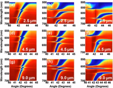
Figure 2 shows the dispersion diagrams extracted from the polarization dependent spectroscopic reflectivity maps of the corresponding Moiré surfaces with the indicated cavity sizes and grating groove depths. It should be noted that when the SPPs at Ag-air interface are excited, angle dependent reflectivity reveals the dispersion characteristics of SPP modes. In optical reflection measurements, the spot size of the incident collimated beam is ⬃1 mm which means that we measure very large number of SPP cavities adjacent to each other. Therefore, the SPP dispersion curves in Fig.2can be assumed to belong to an infinite number of adjacent SPP cavities. It should be noted that the cavity-to-cavity lengths on Moiré surfaces and hence the degree of coupling between the cavities can be adjusted by changing the superperiodicity of the Moiré surface. Thus, cavity sizes and grating groove depths on Moiré surfaces have been changed from 2.5 m to 15.0 m, and 15 nm to 50 nm, respectively. The disper-sion curves show a band gap where a band of wavelengths are forbidden and a well localized cavity mode around 620 nm inside the band gap region appears. At wavelengths be-low⬃500 nm, the reflection decreases due to the absorption in the silver film coated on the coupled cavities. The experi-mental dispersion curves 关Fig. 2兴 have been reproduced by
using finite-difference time-domain 共FDTD兲 calculations for
grating groove depths of 15 nm, 30 nm, and 50 nm. It is well known that periodically patterned metallic surfaces show an energy band gap which prohibits the propagation of modes over a range of wavelengths.13An analytical model for the band gap width and central frequency of the SPP mode has also been proposed. The analytical expression for the mode frequencies at the band edges is of the following form:13
冉
⫾ c冊
2 =冉
0 c冊
2 关1 − 2共Kd兲2兴 ⫾ 2共Kd兲冑
K2 −md 关1 − 3共Kd兲2兴, 共1兲where ⫾, 0, m, d, K, and d are the lower and upper
branch mode stop frequencies, central frequency of the SPP mode, dielectric constant of the metal, dielectric constant of the dielectric material, the grating wave vector, and grating groove depth, respectively. The difference of the lower and upper branch mode stop frequencies gives the width of the plasmonic band gap13
⌬2 c2 =
冋
+ c册
2 −冋
− c册
2 =4K 2共Kd兲冑
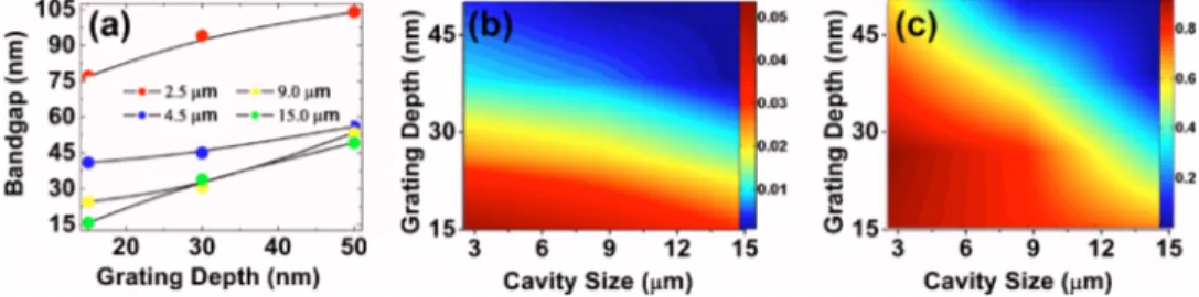
−md 关1 − 3共Kd兲2兴. 共2兲 From the above equation, we find that the band gap strongly depends on the grating wave vector and the grating groove depth. Here, we control the central frequency and width of the band gap by tuning the depth of the grating groove and cavity size while the grating period is fixed to ⬃300 nm. The width of the band gap of the fabricated Moiré surfaces for different cavity sizes increases as the depth of the grating groove increases13关Fig.3共a兲兴.Within the band gap region in the dispersion curves, a clearly noticeable SPP mode can easily be identified. This narrow band indicates the presence of a waveguiding mode of the plasmonic coupled cavities on Moiré surfaces. In a FIG. 1. 共Color online兲 共a兲 Scanning electron microscopy image of adjacent
SPP cavities on a Moiré surface separated by 9.0 m. FDTD calculated two-dimensional electric field distribution in a 9.0 m long SPP cavity at the cavity wavelength of the cavity mode for a grating groove depth of共b兲 10 nm and共c兲 30 nm indicating the stronger localization of the cavity mode upon increasing the grating groove depth.
FIG. 2. 共Color online兲 Experimental dispersion curves reflecting band gap and cavity states of SPPs on Ag coated Moiré surface with varying grating groove depths.关共a兲–共c兲兴 Dispersion curves of SPP for a 2.5 m long SPP cavity. Color map shows the normalized reflectivity of the sample. The blue color is the reflectivity minima whereas the red color is the reflectivity maxima. The upper and lower branches of the band gap are around 600 nm and 650 nm, respectively. The cavity state is at 620 nm. The slope of the cavity mode decreases slowly as the grating groove depth increases.关共d兲– 共f兲兴 Dispersion curves of SPP for a 4.5 m long SPP cavity.关共g兲–共i兲兴 Dis-persion curves of SPP for a 9.0 m long SPP cavity.
previous work, we showed that this wave guiding band can be modeled by using the tight binding approach as it was also applied to CROW type devices. The dispersion of the cavity SPP mode can be described as5
共k兲 = ⍀关1 +cos共kD兲兴, 共3兲
where⍀,, and D are the resonance frequency of the indi-vidual cavity, coupling coefficient, and the size of the cavity, respectively. From the above equation, the group velocity of the SPPs can be found
vg共k兲 = d共k兲/dk = − ⍀Dsin共kD兲, 共4兲
which can be quite small when the cavities are weakly coupled. Therefore, the slope of the dispersion curves gives the group velocity of the SPP cavity modes 关Fig. 2兴. The
group index, ng⬅c/vg, a slow-down factor for the velocity,
c, can also be used in order to express the deviation from
vacuum velocity of light, c. It is clear that the group velocity and the dispersion of SPPs are characterized by the coupling coefficient. This means that in order to slow down SPPs the coupling coefficient, , has to be very small. The calculated group velocities from the experimental dispersion curves are extrapolated in a MATLAB routine for a better display and shown in Fig.3共a兲. Similarly, the coupling coefficient which is expressed as=⌬/2⍀ can be extracted from the disper-sion curves 关Fig. 2兴. The calculated coupling coefficients
from the experimental dispersion curves are extrapolated also in a MATLAB routine for a better representation 关Fig.
3共b兲兴. As it is clear from Fig. 3共c兲, the slow SPPs at the cavity mode can be obtained at large cavity sizes and large grating groove depths. For a given cavity size, as the depth of the grating groove increases the width of the band gap increases13 and the group velocity decreases. Varying the depth of the grating grooves leads to a change in the cou-pling coefficient of the plasmonic coupled cavities, thereby affecting the group velocity of SPPs on plasmonic waveguid-ing band because the couplwaveguid-ing coefficient between the cavi-ties is directly proportional to the group velocity. It is impor-tant to mention here that SPPs with zero group velocity indicates that counter propagation forms a standing wave inside the cavity region and optical energy is stored in the cavity. Slowing down electromagnetic radiation is very im-portant for applications such as enhancing nonlinear pro-cesses and improving optical conversion efficiencies. For
ex-ample, in stimulated emission applications, the effective gain can be increased by slowing down the electromagnetic wave since the effective gain is inversely proportional to the group velocity 共1/vg兲.14
In conclusion, we have investigated, through experi-ments and simulations, slow SPPs and controlled the group velocity of SPPs on plasmonic coupled cavities. The SPPs have been slowed down by varying the depth of the grating groove as well as the cavity size. The group velocity of the coupled cavity mode depends strongly on the coupling coef-ficients between the adjacent cavities. The slow SPPs at the coupled cavity modes can be reached at large cavity sizes and large grating groove depths. Stronger localization of the SPP cavity mode can be achieved when the grating groove depth is increased. Small group velocities and confined be-havior of SPPs are promising for plasmonic nonlinear and spectroscopic applications, and coupled plasmonic cavities on Moiré surfaces are good candidates for this purpose.
S. Balci would like to acknowledge financial support of TUBITAK through a BİDEB grant. This work has been sup-ported in part by a grant from TUBITAK 共Grant No. 104M421兲 and by EU 7th Framework Project, Unam-Regpot 共Grant No. 203953兲.
1L. V. Hau, S. E. Harris, Z. Dutton, and C. H. Behroozi,Nature共London兲 397, 594共1999兲.
2P. C. Ku, F. Sedgwick, C. J. C. Hasnain, P. Palinginis, T. Li, H. Wang, S. W. Chang, and S. L. Chuang,Opt. Lett. 29, 2291共2004兲.
3T. Baba,Nat. Photonics 2, 465共2008兲.
4A. Yariv, Y. Xu, R. K. Lee, and A. Scherer,Opt. Lett. 24, 711共1999兲. 5A. Kocabas, S. S. Senlik, and A. Aydinli,Phys. Rev. Lett. 102, 063901
共2009兲.
6J. C. Weeber, A. Bouhelier, G. C. Francs, S. Massenot, J. Grandidier, L. Markey, and A. Dereux,Phys. Rev. B 76, 113405共2007兲.
7Y. Gong and J. Vuckovic,Appl. Phys. Lett. 90, 033113共2007兲. 8W. D. Wilson,Science 295, 2103共2002兲.
9H. Raether, Surface Plasmons共Springer, Berlin, 1986兲.
10S. C. Kitson, W. L. Barnes, and J. R. Sambles,Phys. Rev. B 52, 11441 共1995兲.
11P. Berini,Adv. Opt. Photon. 1, 484共2009兲.
12L. Baltog, N. Primeau, R. Reinisch, and J. L. Coutaz,Appl. Phys. Lett. 66, 1187共1995兲.
13W. L. Barnes, T. W. Preist, S. C. Kitson, J. R. Sambles, N. P. K. Cotter, and D. J. Nash,Phys. Rev. B 51, 11164共1995兲.
14K. Sakoda,Opt. Express 4, 167共1999兲.
FIG. 3. 共Color online兲 共a兲 Plasmonic band gap of Moiré surfaces with different cavity sizes as a function of the grating depth. 共b兲 Group velocities in c and 共c兲 coupling coefficients of SPP cavities on Moiré surfaces calculated from the experimental dispersion curves. The colored bars in the right hand side of 共b兲 and共c兲 indicate the coupling coefficient and the group velocity, respectively. The calculated data are extrapolated inMATLABfor a better view.